


1
CAUTION: These devices are sensitive to electrostatic discharge; follow proper IC Handling Procedures.
1-888-INTERSIL or 1-888-468-3774
|
Copyright Intersil Americas Inc. 2011. All Rights Reserved
Intersil (and design) is a trademark owned by Intersil Corporation or one of its subsidiaries.
All other trademarks mentioned are the property of their respective owners.
Application Note 1655
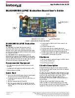
ISL8200MEVAL1PHZ Evaluation Board User’s Guide
ISL8200MEVAL1PHZ Evaluation
Board
The ISL8200M is a complete 10A step-down current
share-able switch mode power module in a low profile
package. It can be used in standalone single-phase operation
as well as current shared applications where multiple modules
are connected in parallel.
The ISL8200MEVAL1PHZ evaluation board is used to
demonstrate performance of the ISL8200M in a single phase
setup. The input voltage is from 3V to 20V, and the output can
support a 10A maximum load with a voltage range from 0.6V
up to 6V with the proper output capacitor rating.
Recommended Equipment
• 0V to 20V power supply with at least 15A source current
capability.
• One Electronic Load capable of sinking current up to 10A.
• Digital multi-meters (DMMs).
Quick Start
1. Connect the PVIN and GND banana jacks to a power supply
and connect a load to the VOUT and GND lugs.
2. A multimeter can be hooked to TP310 (+) and TP34 (-) to
monitor VOUT.
3. Open the jumpers marked PVIN and VCC.
4. Short the jumpers marked 1.2V and FIXED. This sets the
output voltage to 1.2V and sets the OCP trip point its open
condition.
5. Push the toggle on SW1 to the left (with respect to the
board above).
6. Set the input supply to 12V.
7. Set the electronic load to a desired load current.
8. Enable the power supply first and then the load, the LED for
PGOOD will be red when the module is not regulating.
9. Push the toggle on SW1 to the right, the PGOOD LED should
now be green to indicate proper operation.
Shutdown
1. Disable the device by pushing the toggle on SW1 to the left.
2. Turn off the electronic load.
3. Turn off the power supply.
Circuits Description
PVIN and GND banana plugs are the input power terminals.
Two input electrolytic caps footprint are provided to handle the
input current ripple.
Two Sanyo Poscaps (2TPF330M6, 330µF, ESR 6m
Ω
) are used
as output E-caps. These poscaps are rated for output voltages
up to 2V, so they should be removed if a higher VOUT is
required. The footprints of the Sanyo capacitors can
accommodate T530 (ultra-low ESR) tantalum capacitors for
higher voltages.
VOUT and GND are output lugs for load connections.
VSEN+ and VSEN- are output voltage sensing points. These
pins can be used to monitor and evaluate the system voltage
regulations. If the user wants to use these test posts for
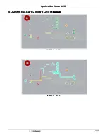
FIGURE 1. ISL8200MEVAL1PHZ EVALUATION BOARD
V
IN
= 3V TO 20V
V
OUT
LOAD UP TO 10A
V
OUT
REMOTE SENSING
POINTS
PGOOD
MODULE
GROUP
DIMENSIONS: 2.5 X 4.5 INCHES
V
OUT
MONITORING POINTS
August 18, 2011
AN1655.0


