KSS SEATING SYSTEM
CHILD/JUNIOR SIZES: 10R, 12R, 14R, 16R
ADULT SIZES: 16T, 18T, 20T
STORM JR. TRANSPORT READY OPTION (TRRO) 12R, 14R, 16R
1
Assembly, Installation, and Operating Instructions
NOTE: The KSS seating system is defined as a
seating system which includes the following:
CHILD/
STORM Jr.
JUNIOR
ADULT
(TRRO)
10R, 12R, 16T,18T
12R, 14R
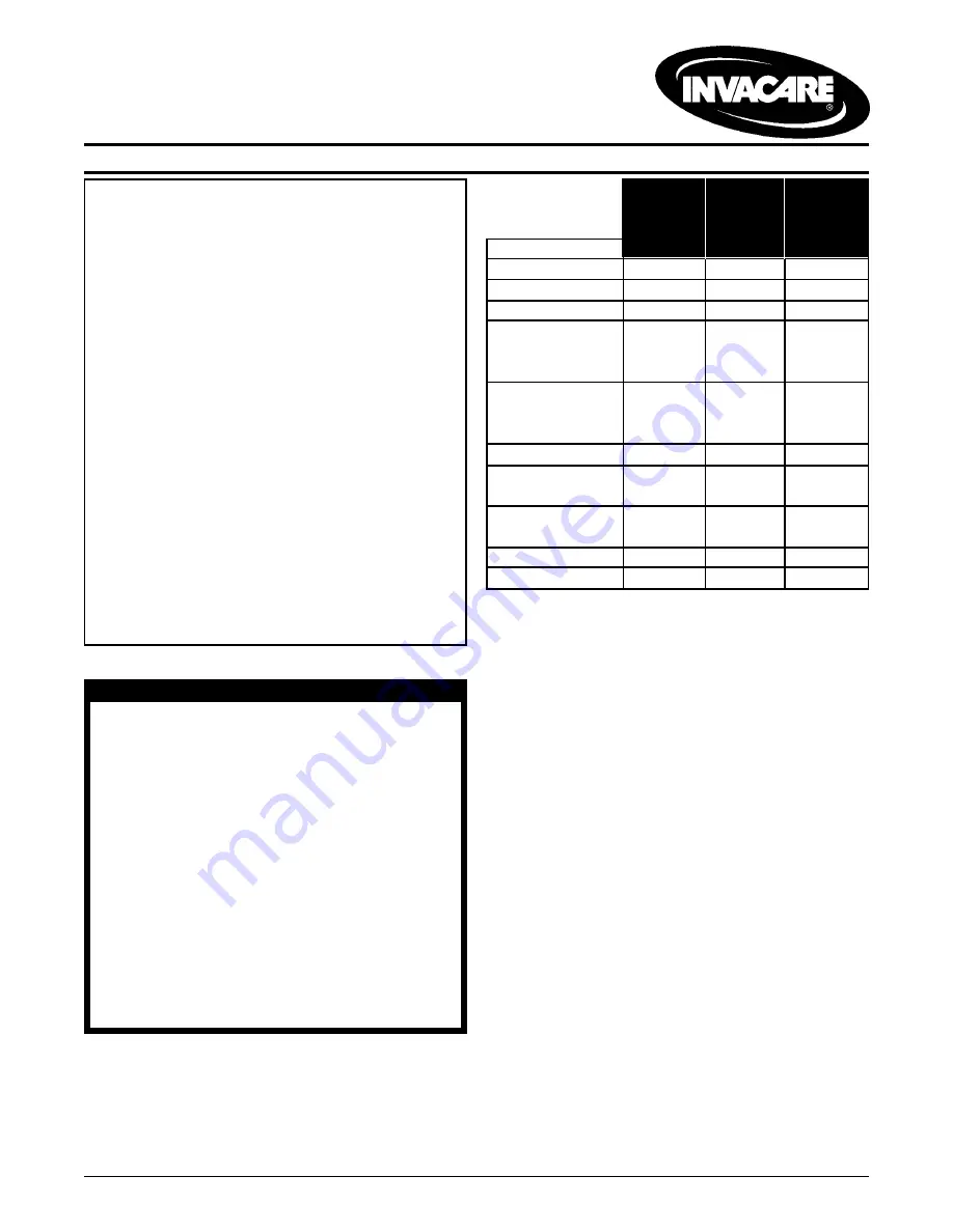
FEATURES
14R, 16R
20T
16R
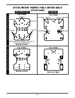
Curved Back
Standard Standard Standard
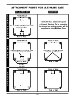
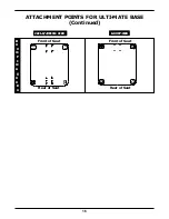
Ulti-Mate Base
Standard Standard Standard
Neck Support
Standard Standard Standard
Lateral Supports:
Fixed
Standard Standard Standard
Swingaway
Optional
Optional Optional
Growth Bracket: Standard
N/A
Standard
90
0
Angle
Standard Standard Standard
Adj. Angle
Optional
Optional
N/A
Lap Belt
Standard Standard Standard
Twist Release
Cane Clamp
Standard Standard Standard
Quick Release
Rail Clamp
Standard Standard Standard
Abductor
Optional
Optional Optional
Shoulder Support Optional
Optional Optional
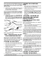
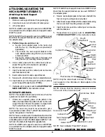
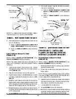
ATTACHING/ADJUSTING THE
FIXED GROWTH BRACKET
NOTE: This procedure only applies the Child/Junior Sizes.
All other procedures are applicable to both the Child/
Junior and Adult Sizes.
Attaching the Growth Bracket
NOTE: Additional mounting hooks and mounting screws
are supplied for the Ulti-Mate Seat and Curved Back.
This additional hardware is taking the place of the growth
bracket.
1. Remove the curved back, Ulti-Mate Base, and growth
bracket from their respective packages.
2. Unzip center panel of the back cover, exposing the
six (6) T-nutted mounting holes.
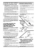
NOTE: Make sure the growth bracket is positioned cor-
rectly. The flat portion of the growth bracket provides depth
adjustment for the Ulti-Mate Base. The angled portion of
the growth bracket provides height adjustment for the
Curved Back. See FIGURE 1.
3. Install four (4) of the mounting screws through the
holes in the growth bracket and into the back shell.
Securely tighten.
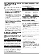
SPECIAL NOTES
WHEELCHAIR TIE-DOWN RESTRAINTS AND SEAT RE-
STRAINTS Invacare recommends that wheelchair
users NOT be transported in vehicles of any kind
while in wheelchairs. As of this date, the Depart-
ment of Transportation has not approved any tie-
down systems for transportation of a user while in
a wheelchair, in a moving vehicle of any type.
It is Invacare’s position that users of wheelchairs
should be transferred into appropriate seating in
vehicles for transportation and use be made of
the restraints made available by the auto
industry. Invacare cannot and does not recom-
mend any wheelchair transportation systems.
AS REGARDS RESTRAINTS - SEAT POSITIONING
STRAPS - IT IS THE OBLIGATION OF THE DME DEALER,
THERAPISTS AND OTHER HEALTH CARE PROFESSION-
ALS TO DETERMINE IF A SEAT POSITIONING STRAP IS
REQUIRED TO ENSURE THE SAFE OPERATION OF THIS
EQUIPMENT BY THE USER. SERIOUS INJURY CAN OC-
CUR IN THE EVENT OF A FALL FROM A WHEELCHAIR.
SAFETY SUMMARY
WARNING
DO NOT install this equipment without first read-
ing and understanding this instruction sheet. If you
are unable to understand the WARNINGS, CAU-
TIONS and INSTRUCTIONS, contact a health-care
professional , dealer or technical personnel be-
fore attempting to install this equipment - other-
wise, injury or damage may occur.
Ensure that the seat is fixed to the wheelchair. A
loose seat may lead to potentially dangerous
situations with positioning devices.
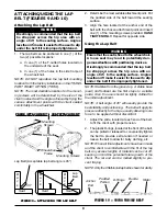
It is strongly recommended that the lap belt be
strapped across the hip area with an angle of
45
o
to the seating surface. Angles less than 45
o
make it easier for the user to slip under the belt if
it is improperly tightened.