background image

Owner’s Operator and Maintenance Manual

DEALER:

 This manual MUST be given to 

the user of the wheelchair.

USER:

 BEFORE using this wheelchair, read 

this manual and save for future reference.

For more information regarding 

Invacare products,  parts, and services, 

please visit www.invacare.com

Everyday and Sport Series 

Wheelchairs

Top End Everyday Series

Terminator™ Titanium and Titanium Heavy Duty
Terminator™ Everyday and Everyday Heavy Duty

Top End Sports Series

Terminator™ BB

X-Terminator™ BB

Paul Schulte Signature BB

X-Terminator™ Titanium

X-Terminator™ QR

Transformer™ All Sport

T-5 Tennis Elite

®

Summary of Contents for Top End T-5 Tennis Elite

Page 1: ... information regarding Invacare products parts and services please visit www invacare com Everyday and Sport Series Wheelchairs Top End Everyday Series Terminator Titanium and Titanium Heavy Duty Terminator Everyday and Everyday Heavy Duty Top End Sports Series Terminator BB X Terminator BB Paul Schulte Signature BB X Terminator Titanium X Terminator QR Transformer All Sport T 5 Tennis Elite ...

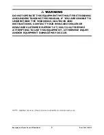
Page 2: ...STANDING THIS MANUAL IF YOU ARE UNABLE TO UNDERSTAND THE WARNINGS CAUTIONS AND INSTRUCTIONS CONTACT YOUR INVACARE DEALER OR INVACARE CUSTOMER SUPPORT AT 800 532 8677 BEFORE ATTEMPTING TO USE THIS EQUIPMENT OTHERWISE INJURY AND OR EQUIPMENT DAMAGE MAY OCCUR NOTE Updated versions of this manual are available on www invacare com ...

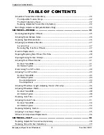
Page 3: ...e of Weight Distribution 19 Reaching Leaning and Bending Forward 20 Reaching Leaning Backwards 20 Tipping 21 Tipping Curbs 21 Stairways 22 Transferring To and From Other Seats 23 SECTION 3 SAFETY INSPECTION 24 Safety Inspection Checklist 24 Inspect Initially 24 Inspect Adjust Weekly 25 Inspect Adjust Monthly 25 Inspect Adjust Periodically 26 Troubleshooting 26 Maintenance 27 Maintenance Safety Pre...

Page 4: ...t 38 Repairing Replacing Rear Wheel Tire Tube 38 Opening Closing Camber Clamps 39 Adjusting Rear Wheel Camber 41 Camber Tube 2000 41 A4 Camber System 41 Determining Toe In Toe Out 42 Adjusting Toe In Toe Out 43 Camber Tube 2000 43 A4 Camber System 44 Course Adjustment 44 Fine Adjustment 45 Adjusting Wheelbase Length Adjusting Center of Gravity 46 Adjusting Wheelbase Width 48 Camber Tube 2000 48 A4...

Page 5: ...alling the X Terminator Footrest 64 Adjusting the X terminator and Transformer Footrests 65 Depth 65 Angle 65 X Terminator Height 65 Transformer Height 65 Adjusting Replacing Anti tipper 66 Adjusting Anti tipper 67 Replacing Anti tipper 67 Installing Removing Adjusting Swivel Anti Tip 68 Installing Depth Adjustment 68 Removing 68 Adjusting Height 69 All Wheelchairs with Swivel Anti tip Except Paul...

Page 6: ...aintenance tips and industry news 4 Invacare can contact you or your provider if servicing is needed on your product 5 It will enable Invacare to improve product designs based on your input and needs Register ONLINE at www invacare com or Complete and mail the form on the next page Any registration information you submit will be used by Invacare Corporation only and protected as required by applic...

Page 7: ...________________________________________________________ 7 Would you like information sent to you about Invacare products that may be available for a particular medical condition Yes No If yes please list any condition s here and we will send you information by email and or mail about any available Invacare products that may help treat care for or manage such condition s __________________________...

Page 8: ...Everyday and Sport Series Wheelchairs 8 Part No 1114851 Fold here Fold here Cut Along Line Invacare Product Registration Form Please Seal with Tape Before Mailing ...

Page 9: ...le of any type It is Invacare s position that users of wheelchairs should be transferred into appropriate seating in vehicles for transportation and use be made of the restraints made available by the auto industry Invacare cannot and does not recommend any wheelchair transportation systems AS REGARDS RESTRAINTS SEAT POSITIONING STRAPS IT IS THE OBLIGATION OF THE DME DEALER THERAPISTS AND OTHER HE...

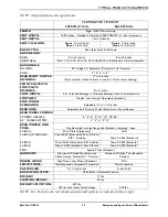
Page 10: ...OOT WIDTH 9 to 12 inches Average is 10 inches between front of footrest bars FOOTREST Tubular 4 inch Height Adjustable Standard SIDE WHEEL CLEARANCE Adjustable 1 2 to 1 1 2 inches REAR AXLE Adjustable Axle Position Quick Standard or Quad Release REAR WHEEL CAMBER CAMBER TUBE 2000 0 3 6 9 12 15 18 20 A4 CAMBER SYSTEM 0 3 6 9 12 Optional REAR WHEELS AND TIRES Double walled rim high flange hub Standa...

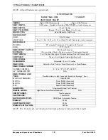
Page 11: ...IDTH 9 to 12 inches Average is 10 inches between front of footrest bars FOOTREST Tubular 4 inch Height Adjustable Standard SIDE WHEEL CLEARANCE Adjustable 1 2 to 1 1 2 inches REAR AXLE Adjustable Axle Position Quick Standard or Quad Release REAR WHEEL CAMBER CAMBER TUBE 2000 0 3 6 9 12 15 18 20 A4 CAMBER SYSTEM 0 3 6 9 12 REAR WHEELS AND TIRES Double walled rim high flange hub Standard Spinergy Sp...

Page 12: ...XED 0 3 6 or 9 REAR FRONT CASTER DISTANCE 22 24 and 26 inches From outside of back of frame to center of front caster housing FOOT WIDTH 9 to 12 inches Average is 10 inches between front of footrest bars FOOTREST Tubular 4 inch Height Adjustable Standard SIDE WHEEL CLEARANCE Adjustable 1 2 to 1 1 2 inches REAR AXLE Adjustable Axle Position Quick Standard or Quad Release REAR WHEEL CAMBER CAMBER TU...

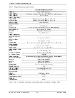
Page 13: ... 16 to 20 inches in 1 inch increments BACK ANGLE Fixed 0 Set at 90 to floor WHEELBASE 16 17 18 or 19 inches FOOTREST Tubular 4 inch Height Adjustment SIDE WHEEL CLEARANCE Adjustable 1 2 to 1 1 2 inches REAR AXLE Fixed Axle Position Quick Release Standard REAR WHEEL CAMBER Fixed 12 15 18 or 20 REAR WHEELS Double Walled Rim High Flange Hub Standard Cross Spoke Spinergy Spox Optional 24 INCH STANDARD...

Page 14: ...Adjustable in 5 increments FIXED Set at 90 to floor FRAME LENGTH FRAME W FOLDING BACK Seat depth plus 10 inches FRAME W FIXED BACK Seat depth plus 8 inches FOOTREST Recessed 4 inch Height Angle Adjustable Solid Platform Standard SIDE WHEEL CLEARANCE Adjustable 1 2 to 1 1 2 inches REAR AXLE Adjustable Axle Position Quick Release REAR WHEEL CAM BER Fixed 12 15 18 or 20 CAMBER TUBE 2000 0 3 6 12 15 1...

Page 15: ...and column occur follow across the chart and refer to the procedure to maintain the proper stability safety and handling of the racing chair Operating Information To determine and establish your particular safety limits practice bending reaching and transferring activities in several combinations in the presence of a qualified healthcare professional before attempting active use of the wheelchair ...

Page 16: ...air DO NOT stand on the frame of the wheelchair Check all allen screws that secure the footrest raised footrest system to the chair frame before using the wheelchair especially if engaging in any contact sport Anti tippers MUST BE attached at all times Inasmuch as the anti tippers are an option on this wheelchair you may order with or without the anti tippers Invacare strongly recommends ordering ...

Page 17: ...se of its wheelchairs as a weight training apparatus Invacare wheelchairs have not been designed or tested as a seat for any kind of weight training If occupant uses said wheelchair as a weight training apparatus Invacare shall not be liable for bodily injury and the warranty is void Weight Limitation Invacareʹs Top End Everyday and Sport Series wheelchairs Terminator Titanium Terminator Everyday ...

Page 18: ...SITIONING STRAP is an option on this wheelchair you may order with or without the seat positioning strap Invacare strongly recommends ordering the seat positioning strap as an additional safeguard for the wheelchair user The seat positioning strap is a positioning belt only It is not designed for use as a safety device withstanding high stress loads such as auto or aircraft safety belts If signs o...

Page 19: ...he user and or assistant s When learning a new assistance technique have an experienced assistant help you before attempting it alone Percentage of Weight Distribution WARNING DO NOT attempt to reach objects if you have to move forward in the seat or pick them up from the floor by reaching down between your knees The position of the footrest camber tube back angle the tautness of the back upholste...

Page 20: ...itional weight onto the rear wheels Reaching Leaning and Bending Forward Position the front casters so that they are extended as far forward as possible and engage wheel locks WARNING DO NOT attempt to reach objects if you have to move forward in the seat or pick them up from the floor by reaching down between your knees Reaching Leaning Backwards WARNING DO NOT lean over the top of the back uphol...

Page 21: ...le injury to occupant and or assistant s can occur Transfer to an everyday use wheelchair is recommended if any such obstacles may be encountered After mastering the techniques of tipping the wheelchair use the following method to tackle curbs short stairs etc Turn the anti tippers if equipped so the wheels are facing UP Unless the first assistant has exceptional upper body strength it is recommen...

Page 22: ... wheelchair is recommended DO NOT attempt to lift the wheelchair by any removable detachable parts Lifting by means of any removable detachable parts of a wheelchair may result in injury to the user or damage to the wheelchair Extreme caution is advised when it is necessary to move an occupied wheelchair up or down a stairway Invacare recommends that if possible the user be removed from the wheelc...

Page 23: ... attempting to transfer in or out of the wheelchair every precaution should be taken to reduce the gap distance Turn both casters parallel to the object you are transferring onto Also be certain the wheel locks are engaged to help prevent the wheels from moving When transferring position yourself as far back as possible in the seat This will pre vent damaged upholstery and the possibility of the w...

Page 24: ...to one side Ensure wheel locks DO NOT interfere with tires when rolling Ensure pivot points are free of wear and looseness Ensure wheel locks are easy to engage Inspect seat and back upholstery for rips or sagging Inspect upholstery fastening flaps to ensure they securely latch Inspect seat positioning strap for any signs of wear Ensure buckle latches Verify hardware that attaches strap to frame i...

Page 25: ...pokes for bent or broken spokes Ensure All spokes uniformly tight CAUTION As with any vehicle the wheels and tires should be checked periodically for cracks and wear and should be replaced if damaged Inspect wheel fork assembly for proper tension by spinning caster caster should come to a gradual stop Inspect tires for flat spots and wear Ensure that casters are free of debris If pneumatic tires c...

Page 26: ...ely tightened Ensure that casters are free of debris Ensure no excessive side movement or binding when lifted and spun Inspect handrims for signs of rough edges or peeling Clean upholstery and armrests CAUTION As with any vehicle the wheels and tires should be checked periodically for cracks and wear and should be replaced if damaged Ensure wheel bearings are clean and free of moisture Check that ...

Page 27: ...dles on page 37 WARNING DO NOT use WD 40 3 in 1 oil or other penetrating lubricants on quick release axles or camber inserts Otherwise binding and or damage to the wheelchair may occur 3 Clean quick release axles and camber inserts once a week with a Teflon lubricant WARNING DO NOT use your wheelchair unless it has the proper tire pressure p s i DO NOT overinflate the tires Failure to follow these...

Page 28: ... back of this manual 7 Periodically check handrims to ensure they are secured to the rear wheels Refer to Handrim Replacement on page 38 8 Periodically adjust wheel locks as tires wear Refer to Wheel Lock Adjustment Replacement on page 56 9 Periodically check caster wheel bearings to make sure they are clean and free from moisture Use a Teflon lubricant if necessary 10 Check upholstery for sagging...

Page 29: ...use make sure all attaching hardware is tightened securely otherwise injury or damage may occur Unfolding Folding the Back WARNING Back MUST be locked securely in place before using the wheelchair NOTE For this procedure refer to FIGURE 4 1 1 To unfold the back lift up on the back canes and pull back towards the rear of the wheelchair until it locks into place 2 To fold the back pull up on the bac...

Page 30: ...20 inch pounds 80 85 foot pounds NOTE As shown in FIGURE 4 2 the adjustment cam can be rotated to several different positions thus changing the overall back angle relative to the seat rail FIGURE 4 2 Back Angle Adjustment 95 Back Angle to Seat Rail 90 Back Angle to Seat Rail 80 Back Angle to Seat Rail 85 Back Angle to Seat Rail 75 Back Angle to Seat Rail Back Cane Indexing Notch Cam Seat Rail Back...

Page 31: ...emoving Foldover Back Upholstery 1 Unfasten the two fastening flaps that secure the bottom of the existing back upholstery to the back canes 2 Unfold the top of the back upholstery 3 Lift up on the existing back upholstery and remove from the wheelchair Installing Foldover Back Upholstery 1 Install the new back upholstery onto the back canes 2 Wrap the end of a fastening flap around the back cane ...

Page 32: ...ly to support and or assist the extensor muscles The Back Upholstery Cover NOTE The back upholstery cover is designed for three reasons The first is as a modesty cover The second is to keep the cushion from sliding out of the back of the wheelchair The third is a sacral support depending upon how far or tight the flap is pulled under the seat cushion Replacing Adjustable Tension Back Upholstery 1 ...

Page 33: ...e securely fastened BEFORE applying the back upholstery cover The adjustable back should be checked whenever enter ing the wheelchair to ensure that the fastening straps are securely fastened 9 Secure the back upholstery cover fastening strap to the back of the adjustable back upholstery fastening strap 10 Flip the back upholstery cover over the adjustable back upholstery and secure the fastening ...

Page 34: ...ane inserts 3 Reinstall the fastening flaps onto the back canes NOTE The fastening flap with logo is for the left back cane NOTE Right and left is determined by sitting in the wheelchair 4 Adjust the new back upholstery to the desired tautness Refer to Adjustable Tension Back Upholstery on page 32 FIGURE 4 5 Back Height Adjustment Adjustable Backs Only ORIGINAL BACK HEIGHT IN INCHES 11 15 14 18 16...

Page 35: ...away from the wheelchair Quad Release Lift up on the handle of the quad release axle and pull axle and wheel away from the wheelchair 2 Repeat STEP 1 for the opposite rear wheel 3 Reinstall the rear wheels onto the wheelchair by reversing STEPS 1 2 WARNING Pull on the rear wheel to make sure the detent pin and locking pins of the quick quad release axle are fully released before operating wheelcha...

Page 36: ...elease axle from the wheelchair Refer to Removing Installing Rear Wheels on page 35 2 Remove existing quick release axle from rear wheel 3 Insert new quad release axle through rear wheel hub 4 Slide locking collar onto quad release axle until it is snug against rear wheel and tighten securely with allen screw 5 Reinstall rear wheel and the quad release axle onto the wheelchair Refer to Removing In...

Page 37: ...rotate the quad release handle approximately one quarter turn counterclockwise 4 Tighten the locking screw FIGURE 5 4 Adjusting Quad Release Handles 5 Reinstall the rear wheel and quad release axle onto the wheelchair Refer to Removing Installing Rear Wheels on page 35 6 Flip the handle of the quad release axle down to release the detent pin ensuring that the locking pins are fully released 7 Repe...

Page 38: ... the handrim to the rear wheel 4 Remove the existing handrim 5 Install new handrim by reversing STEPS 2 4 WARNING DO NOT inflate tire until it is completely assembled Otherwise injury or damage may result 6 Inflate tire to correct psi rating on the sidewall of tire 7 Reinstall rear wheel to the wheelchair Refer to Removing Installing Rear Wheels on page 35 8 Repeat STEPS 1 7 for opposite rear whee...

Page 39: ...heelchair otherwise personal injury or damage to the wheelchair may occur CAUTION A4 CAMBER SYSTEM ONLY DO NOT close the quick release levers or tighten the socket screws or hex screws without camber inserts in the axle tube Damage to the axle tube will occur NOTE For this procedure refer to FIGURE 5 6 1 Perform one of the following to open a camber clamp Quick Release Levers Pull the quick releas...

Page 40: ...URE 5 6 Opening Closing Camber Clamps Side View of Quick Release Lever Camber Clamp Closed Position Open Position Quick Release Lever Side View of Standard Camber Clamp Camber Clamp Socket Screw Rear View of Suspension Camber Clamp Camber Clamp Hex Screw Camber Insert Axle Tube ...

Page 41: ...marks showing of the camber insert outside of the axle tube The camber inserts will not be securely tightened in the axle tube Possible injury to the user and or damage to the wheelchair may occur 6 Position the camber insert to the desired position Make sure there is no more than 3 inches 12 indexing marks of the camber inserts outside of the axle tube 7 Slide the indexing ring on the camber inse...

Page 42: ...ted on the sidewall of the tire 2 Measure the distance between the centerlines at the rear and front of the rear wheels at approximately 12 inches from the ground floor FIGURE 5 8 NOTE For optimum accuracy perform STEP 2 with the wheelchair occupied 3 Determine difference between two measurements If difference between the two measurements is greater than 1 2 inch 0 1 4 inch for maximum rollability...

Page 43: ...amps Refer to Opening Closing Camber Clamps on page 39 4 Measure the distance between the center lines at the rear and front of the rear wheels at approximately 12 inches from the ground floor Refer to Determining Toe In Toe Out on page 42 5 Repeat STEPS 1 4 until the toe in toe out measurement is less than 1 2 inch 0 1 4 inch for maximum rollability FIGURE 5 9 Adjusting Toe In Toe Out Camber Tube...

Page 44: ...DARD AND SUSPENSION CAMBER CLAMPS Make sure the hex screws are securely tightened before using the wheelchair otherwise personal injury or damage to the wheelchair may occur 4 Close the camber clamp Refer to Opening Closing Camber Clamps on page 39 5 Measure the distance between the center lines at the rear and front of the rear wheels at approximately 12 inches from the ground floor Refer to Dete...

Page 45: ...when the right adjustment ring is adjusted to the other camber the left adjustment ring will not touch the camber clamp Fine Adjustment NOTE For this procedure refer to FIGURE 5 11 NOTE This adjustment is required anytime the camber insert is repositioned 1 Open the camber clamp Refer to Opening Closing Camber Clamps on page 39 2 Slowly rotate the axle tube until the stop on the opposite adjustmen...

Page 46: ...justing Wheelbase Length Adjusting Center of Gravity WARNING ALWAYS perform this procedure in the presence of an assistant The position of the footrest camber tube back angle the tautness of the back upholstery as well as the user s condition are directly related to the wheelchairs stability Any change to one or any combination of the five may cause the wheelchair to decrease in stability Use EXTR...

Page 47: ...GURE 5 12 Adjusting Wheelbase Length Adjusting Center of Gravity Non Suspension Securely tighten the hex screw that secures one of the top clamps to the wheelchair frame Suspension Securely tighten the two hex screws that secure one of the top clamps to the wheelchair frame NOTE Securely tightening one hex screw at a time ensures that the camber clamps will sit flush on the wheelchair frame 4 Repe...

Page 48: ...t for this procedure FIGURE 5 13 Adjusting Wheelbase Width Camber Tube 2000 A4 Camber System NOTE For this procedure refer to FIGURE 5 14 1 Open the camber clamp Refer to Opening Closing Camber Clamps on page 39 WARNING NEVER position the camber inserts in the axle tube with more than 3 inches 12 indexing marks showing of the camber insert outside of the axle tube The camber inserts will not be se...

Page 49: ...to the bottom of the wheelchair frame NOTE There is no need to remove the two camber clamps when replacing the axle tube 1 A4 Camber System Only Note the position of the camber inserts so they can be installed at the same position in the new axle tube 2 Open the camber clamps Refer to Opening Closing Camber Clamps on page 39 3 Remove the two rear wheels Refer to Removing Installing Rear Wheels on ...

Page 50: ... camber inserts will not be securely tightened in the axle tube Possible injury to the user or damage to the wheelchair may occur 12 A4 Camber System Only Install camber inserts into the NEW axle tube and slide the camber inserts to the position noted in STEP 1 Make sure there are no more than 3 inches 12 indexing marks of the camber inserts outside of the axle tube 13 A4 Camber System Only Slide ...

Page 51: ... or damage to the wheelchair may occur CAUTION A4 CAMBER SYSTEM ONLY DO NOT close the quick release levers or tighten the hex screws without camber inserts in the axle tube Damage to the axle tube will occur NOTE Stand behind the wheelchair to determine left or right Axle Tube Camber Clamp Camber Insert Set Screw Indexing Ring Rear of Wheelchair Camber Insert Toe Adjustment Ring Slot in Axle Tube ...

Page 52: ...r to Opening Closing Camber Clamps on page 39 2 Loosen the set screw that secures each toe adjustment ring to the axle tube FIGURE 5 17 3 Using an ʺLʺ square rotate the axle tube until the flat edge of the camber insert is at a 90 angle with the ground floor as shown in FIGURE 5 17 4 Close the right camber clamp Refer to Opening Closing Camber Clamps on page 39 5 Rotate the Left toe adjustment rin...

Page 53: ... to STEP 17 Toe In Toe Out Measurement is Not Within 1 8 inch i Repeat STEP 1 ii Loosen the set screw on the right toe adjustment ring iii Repeat STEP 3 iv Repeat STEPS 12 16 until toe in toe out measurement is within 1 8 inch 17 If desired reposition camber inserts to the desired degree of camber Refer to Adjusting Rear Wheel Camber on page 41 FIGURE 5 17 Adjusting the Axle Tube A4 Camber System ...

Page 54: ...the following Non Suspension Fork Install the new caster bolt locknut and axle spacers onto the fork and securely tighten Suspension Fork Perform the following steps i Determine the desired mounting hole for the caster installation ii Line up the front caster and two spacers with the mounting hole in the fork determined in STEP B i iii Reinstall the mounting screw threaded sleeve assembly through ...

Page 55: ...FIGURE 5 19 Adjusting Front Caster Height 1 Place the wheelchair on a flat surface 2 Remove the dust cover on the fork assembly 3 Remove the locknut that secures the front caster fork to the wheelchair frame 4 Position a large right triangle or ʺLʺ square on the flat surface and against the caster housing that is welded to the wheelchair frame 5 Adjust the height of the front casters by either add...

Page 56: ...he High Low Mount Wheel Lock i Remove the locknuts and hex allen screws and remove existing wheel lock from the wheelchair ii Install the new wheel lock and adjust Adjusting the High Low Mount Wheel Lock i Measure the distance between the wheel lock shoe and the rear wheel ii Slide the wheel lock along the wheelchair until the measurement is between 5 32 and 5 16 inches iii Tighten the wheel lock ...

Page 57: ...placement Front Rear Wheelchair Frame Low Mount Wheel Lock Wheel Lock Shoe Hex Screws Wheelchair Frame Wheel Lock Shoe High Mount Wheel Lock NOTE Rear wheel not shown for clarity NOTE High mount wheel lock shown for clarity Wheelchair Frame Wheel Lock Shoe Rear Wheel 5 32 to 5 16 inch Gap Wheel Lock Adjustment ...

Page 58: ...ing seat upholstery 5 Place the wheelchair back onto all four wheels NOTE Right and left is determined by sitting in the wheelchair NOTE The seat upholstery MUST be positioned with the three rear adjusting straps towards the rear of the top crossbar for proper installation NOTE Make sure the rear retaining flap is between the wheelchair frame and the back cane support brackets adjustable backs onl...

Page 59: ...efer to FIGURE 6 2 1 Remove the seat cushion from the wheelchair 2 Remove the twelve mounting screws that secure the existing seat upholstery to the seat frame 3 Remove the existing seat upholstery FIGURE 6 2 Replacing Screw On Seat Upholstery Fastening Flaps Seat Upholstery Adjuster Straps Rear Wheelchair Frame Top Bar Top Crossbar Anchor Loop Mounting Screws Seat Upholstery Seat Frame ...

Page 60: ...sired position 4 Adjust the footrest height if desired Refer to Adjusting the X terminator and Transformer Footrests on page 65 5 Align the footrest tubing adjustment holes with the desired wheelchair frame adjustment holes 6 Install the hardware removed in STEP 2 through the adjustment holes aligned in STEP 5 7 Securely tighten all hardware Adjusting Rear Seat Height 1 Loosen the two mounting scr...

Page 61: ... Series Wheelchairs FIGURE 6 3 Adjusting Transformer Seat Height DETAIL A FRONT VIEW Wheelchair Frame Footrest Tubing Coved Washer Mounted Screw Threaded Sleeve Adjustment Holes Half Clamp Mounting Screw Coved Washer Half Clamp DETAIL B Adjustment Screw ...

Page 62: ...RE using the wheelchair ESPECIALLY if engaging in ANY contact sport The footrest assembly MUST be at least 1 3 4 inches above the ground floor to avoid hitting protruding objects when using this wheelchair Adjusting Replacing Standard Footrest NOTE For this procedure refer to FIGURE 7 1 1 Loosen the two allen screws that secure the footrest to the wheelchair frame Replacing the Footrest 1 Remove e...

Page 63: ...g 1 Loosen the four allen screws 2 Adjust clamp on raised footrest to the desired height 3 Securely tighten the four allen screws Replacing Adjusting Optional A4 Footrest NOTE For this procedure refer to FIGURE 7 3 NOTE This procedure is for Terminator Everyday ED wheelchairs Only Replacing the Footrest 1 Loosen but DO NOT remove the two allen screws that secure the footrest to the wheelchair fram...

Page 64: ...rve the angle of footplate for reinstallation 2 Move the footplate to one of two positions to accommodate the user 3 Retighten the four flat screws and locknuts NOTE The settings for positioning the footplates on the half clamps may vary for each end user NOTE The locknuts should lie in the channel of the footplate half clamp Installing the X Terminator Footrest NOTE For this procedure refer to FI...

Page 65: ...amp on raised footrest to the desired height 3 Securely tighten the four allen screws FIGURE 7 4 Installing the X Terminator Footrest Adjusting the X terminator and Transformer Footrests Transformer Height NOTE For this procedure refer to FIGURE 7 5 1 Note the order of the mounting screw coved washers spacer half clamps and mounting screw threaded sleeve and their position on the wheelchair frame ...

Page 66: ...ippers as an additional safeguard for the wheelchair user Anti tippers MUST be fully engaged Ensure the release button of the anti tipper fully protrudes out of the hole in the anti tipper socket Ensure both anti tippers are adjusted to the same height NOTE For this procedure refer to FIGURE 7 1 NOTE To ensure the correct model anti tipper is used refer to FIGURE 7 1 Measurements for anti tippers ...

Page 67: ...sed anti tippers MUST be adjusted to maintain a 1 1 2 to 2 inch clearance between the bottom of the anti tipper wheels and the ground floor This spacing should always be checked whenever adjustments changes are made to the wheelchair Failure to maintain proper spacing may result in the chair tipping over backward causing serious injury or property damage 1 Press in the release button that secures ...

Page 68: ...ustment 1 Loosen set screws on anti tip receivers FIGURE 7 2 2 Slide the swivel anti tip into the anti tip receivers Position swivel anti tip so it is even with wheels on chair or extends beyond them Tighten set screws Removing 1 Loosen set screws on anti tip receivers FIGURE 7 2 2 Slide the swivel anti tip out of the receivers DETAIL A ANTI TIPPER ADJUSTMENT HOLES Top Adjustment Hole Anti Tipper ...

Page 69: ... Schulte Signature BB and T 5 Tennis Elite Models ONLY NOTE For this procedure refer to FIGURE 7 2 Detail A 1 Remove the dust cover on the anti tip caster fork assembly 2 Remove the locknut that secures the anti tip caster fork assembly to the anti tipper 3 Adjust the height of the anti tip caster fork assembly to the desired height by either adding or removing spacers from the fork stem 4 Reinsta...

Page 70: ... FIGURE 8 1 1 Use an allen wrench to hold the outer allen screw 2 While holding the outer allen screw in position remove the inner allen screw from the pivot pin 3 Use the allen wrench to push the pivot pin with outer allen screw out of the mounting hole 4 Remove the existing elastomer 5 Position the new elastomer between the recess in the axle bracket and the recess in the suspension base 6 Compr...

Page 71: ... One mounting screw will not turn 2 Remove the threaded sleeve and mounting screw assembly from the fork DO NOT use excessive force 3 Remove the existing elastomer from the fork 4 Install NEW elastomer determined in STEP 1 into fork NOTE Make sure the elastomer sits in the two recessed areas on the fork 5 Align the mounting holes in the upper and lower portion of the fork 6 Reinstall threaded slee...

Page 72: ...leeve otherwise the fork can become disassembled Possible injury or damage could occur 7 Apply Loctite 242 to the mounting screw 8 Reinstall the mounting screw into the threaded sleeve and tighten securely FIGURE 8 2 Replacing Front Elastomers Mounting Screw Elstaomer Threaded Sleeve Lower Portion of Fork Upper Portion of Fork Mounting Screw Use Loctite 242 ...

Page 73: ...procedures are for Transformer wheelchairs ONLY Installing Removing the Wing Bumper NOTE For this procedure refer to FIGURE 9 1 Installing 1 Slide wing bumper clamps onto caster housing on the Transformer Ensure the wing or bumper is even on both sides 2 Tighten allen screws securely on each side Removing 1 Loosen allen screws on wing bumper clamps 2 Slide up and remove FIGURE 9 1 Installing Remov...

Page 74: ...SECTION 9 WING BUMPER Everyday and Sport Series Wheelchairs 74 Part No 1114851 NOTES ...

Page 75: ...hased your Invacare product In the event you do not receive satisfactory warranty service please write directly to Invacare Top End at the address on the back page Provide dealer s name address date of purchase indicate nature of the defect and if the product is serialized indicate the serial number Do not return products to our factory without our prior consent LIMITATIONS AND EXCLUSIONS THE FORE...

Page 76: ... noted Dual Grip is a registered trademark of Sun Metal Products Inc KIK is a registered trademark of KIK Technology Inc Natural Fit is a registered trademark of Three Rivers Spinergy is a registered trademark of Spinergy Inc 3 in 1 oil is a registered trademark of American Home Products Corporation WD 40 is a registered trademark of WD 40 Company Loctite 242 is a trademark of the Loctite Corporat...

Reviews: