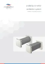
background image

inVENTer iV14R/V

ventilation system

Installation and operating instructions

Summary of Contents for iV14R

Page 1: ...inVENTer iV14R V ventilation system Installation and operating instructions ...

Page 2: ... documentation is an English translation of the original German installation and operating instructions Once installation has been completed it should be passed onto the user tenant owner building management etc The contents of this documentation have been checked for correlation with the hardware and software described However discrepancies cannot be ruled out so complete correlation cannot be gu...

Page 3: ...3 inVENTer iV14R iV14V ventilation system Installation and operating instructions ...

Page 4: ...ctrical connections 24 5 Assembly and installation 26 5 1 Preparation set 26 5 2 Completion set 27 5 3 Information on RAL compliant installation 28 5 4 Creating the wall opening plaster channel 29 5 5 Laying the controller cable 32 5 6 Fitting the wall sleeve 33 5 7 Fitting the sliding sleeve optional 41 5 8 Fitting weather protection hood 09 43 5 9 Fitting the Ohio weather protection hood 48 5 10...

Page 5: ... cover panel 65 6 3 Toppling the inner cover 66 6 4 Replacing dust ilters 67 6 5 Removing installing the thermal accumulator insert 70 6 6 Cleaning the thermal accumulator 73 7 Speciication 74 8 Scope of supply 77 9 Accessories and spare parts 79 10 Servicing and maintenance 81 11 Troubleshooting and disposal 83 12 Warranty and service 85 Company details 87 ...

Page 6: ...of the instruction A keyword above the text indicates the level of risk involved Where several different hazard levels coincide always follow the safety instructions for the highest level DANgER Type and source of risk Immediate risk of serious personal injury Possible consequences of the risk Action to be taken to avoid the risk WARNINg Type and source of risk Potential risk of serious personal i...

Page 7: ...s not suitable for Rooms with corrosive and caustic gases Rooms with extreme dust exposure Drying out buildings Reliable fan operation is only guaranteed in rooms without polluted air The inVENTer ventilation system works with safety extra low voltage Therefore the inVENTer iV14 ventilation unit must not be connected directly to the 230 V power supply it must always be connected via a controller 1...

Page 8: ...mm by attaching a sliding sleeve The sliding sleeve is used to adjust the length precisely to the actual length required The inVENTer iV14 ventilation unit is controlled via one of the following inVENTer system controllers1 ZR8 ZR10 D MZ One The design of the inVENTer iV14 ventilation system is based on experience with fans that comply with DIBt approval Z 51 3 156 Features Pleasant room climate i...

Page 9: ...3 Dust ilter 4 Panel inner cover 5 Wall sleeve 6 Reversible fan 7 Thermal accumulator 8 Weather protection hood base plate sleeve for Ohio weather protection hood 9 Weather protection hood cover weather protection grille iV14V Ohio 10 Exterior wall 11 Insulation 12 Masonry iV14V with inner cover V 284x284 iV14R with inner cover R D290 2 1 4 10 11 12 5 6 7 8 9 2 1 4 5 6 7 8 9 10 12 iV14V with inner...

Page 10: ...ion unit 1 Wall sleeve R D204x450 R D204x650 2 Wall sleeve V 177x177x450 V 177x177x650 Extension set optional Wall sleeve R D204 extension set Wall sleeve V 177x177 extension set Fig 3 Extension sets for iV14R iV14V ventilation unit 1 Extension duct iV14R 200 2 Sliding sleeve R D210x100 3 Extension duct iV14V 200 4 Sliding sleeve V 186x186x100 1 2 2 1 3 4 ...

Page 11: ... cover V 284x284 Inner cover R D290 Fig 5 Inner covers V 284x284 and R D290 1 Pollen ilter available for all inner covers as an option Micro ilter available as an option for the R D290 V 284x284 and V 233x233 inner covers 1 2 1 2 3 4 5 3 4 5 1 Thermal accumulator with insulation 2 Reversible fan 3 Connection terminal for controller 4 Connection terminal for fan 5 Handle 3 1 2 4 3 1 2 4 1 Inner cov...

Page 12: ...r iV14R and iV14V ventilation units with a wall thickness of 250 mm or above The Ohio weather protection hood is to supplement the inVENTer iV14V ventilation unit It was designed for an exterior wall thickness of 150 249 mm in situations where the weather protection hood 09 cannot be used due to the shallow installation depth The Ohio weather protection hood is only suitable for the square wall sl...

Page 13: ...mined The following basic rules apply to the functioning of the ventilation units Paired operation of the ventilation units The volume of supply air should match the volume of extract air Every ventilation unit that is conveying supply air should be assigned to another ventilation unit that is simultaneously conveying extract air The project is used to assign the starting order of the ventilation ...

Page 14: ... of airlow at output level zero Use of the ZR8 Flat controller is recommended in rooms where the ventilation unit should not be switched off in order to maintain ventilation to protect against moisture build up Features Control of the ventilation unit in three operating modes Ininitely variable adjustment of the airlow with rotary button Marking of the airlow at four output levels LED display subj...

Page 15: ...rlow at output level zero Use of the ZR10D Flat controller is recommended in rooms where the ventilation unit should not be switched off in order to maintain ventilation to protect against moisture build up Features Control of the ventilation unit in three operating modes Ininitely variable adjustment of the airlow with rotary button Marking of the airlow at four output levels LED display subject ...

Page 16: ...d in conjunction with additional sensors Through an external interface it can be connected to a potential free loating contact or integrated into an existing home automation system via an analogue input Features Intelligent Clust Air control for up to four different zones in one residential unit Operated by means of touch sensitive keys navigation arrows Backlit display unit Control of the inVENTe...

Page 17: ...ening for wall sleeve iV14V new buildings Wall thickness 210 210 Installation elements Wall sleeve R D204 450 1050 204 Wall sleeve V 177x177 450 1050 177 177 Sliding sleeve R D210x100 100 210 Sliding sleeve V 186x186x100 100 186 186 Weather protection hood 09 23 89 279 313 Ohio weather protection hood 230 247 Inner cover R D290 72 290 Inner cover V 284x284 672 284 284 Inner cover V 220x200 702 223...

Page 18: ...rior wall 2 Minimum distance to adjacent components on exterior wall 250 136 176 210 250 1 450 2 1 4 2 5 3 Ø230 136 176 250 2 1 3 5 250 1 450 2 4 iV14R iV14V 250 123 5 210 123 5 1 4 2 5 3 250 1 1 Wall opening 2 Position of weather protection hood 09 3 Door window frame 4 Outer edge of reveal insulation with plaster 5 Bottom edge of reveal lintel 1 Wall opening new building 2 Position of weather pr...

Page 19: ...ctions Wall sleeves Fig 13 Dimensioned drawing for wall sleeve R D204x450 Fig 14 Dimensioned drawing for wall sleeve V 177x177x450 450 Ø204 4 x M4 3 2 1 A A A A 4 x M4 177 1 3 458 2 A A A A 1 Wall sleeve 2 Fixing element 3 Controller cable recess 1 Wall sleeve 2 Fixing elements 3 Controller cable recess ...

Page 20: ...tion and operating instructions Sliding sleeves Fig 15 Dimensioned drawing for sliding sleeve R D210x100 Fig 16 Dimensioned drawing for sliding sleeve V 186x186x100 100 2 2 A A Ø 2 1 0 A A 1 1 Sliding sleeve 2 Fixing element 186 100 A A A A 2 1 2 1 Sliding sleeve 2 Fixing element ...

Page 21: ...drawing for weather protection hoods Weather protection hood 09 base plate Fig 18 Drilling pattern for weather protection hood 09 base plate 1 Corner drilling dia 8mm min 50 mm deep 279 313 23 89 247 230 110 4 1 2 3 1 Weather protection grille V 230x240 2 Sleeve for Ohio weather protection hood 3 Weather protection hood 09 cover 4 Weather protection hood 09 base plate 4 x Ø 8 240 274 155 245 195 2...

Page 22: ...g for inner cover R D290 Fig 20 Dimensioned drawing for inner cover V 284x284 A A Ø 2 9 0 72 166 217 170 217 A A 1 2 3 4 5 1 Spacer 2 Inner cover base plate 3 Inner cover panel 4 Insulation mat 5 Installation label inVENTer logo 1 Spacer 2 Inner cover base plate 3 Inner cover panel 4 Insulation mat 284 170 217 135 230 238 170 217 A A A 67 A 1 2 3 4 ...

Page 23: ...er cover Flair V 233x233 A A 223 203 203 183 4xØ4 8 166 188 8 55 70 A A 1 2 3 4 1 Spacer 2 Inner cover base plate 3 Inner cover panel 4 Holding plate IB V 220x200 215 179 189 207 217 A A 4xØ4 8 Ø4 3 215 233 A A 61 1 2 4 5 2 6 7 3 1 Spacer 2 Inner cover base plate 3 Sound insulation insert optional 4 Holding plate IB V 233x233 5 Inner cover panel 6 Fixing points for iV14R 7 Fixing points for iV14V ...

Page 24: ...collar to connect stranded wires TIP Exclusively lay the cable while it is not live Disconnect the power supply to the controller before sealing connecting the cable Seal connect the cable only while it is not live TIP Use stranded wires to connect the fan bus to the ventilation unit The fan bus terminal can take wires with a cross section of up to 1 5 mm This makes it possible to arrange the vent...

Page 25: ...locking screws are pointing up and visible The LED is not illuminated see ig 24 Start settings Start direction for extract air In supply air mode the green connector is rotated The locking screws are pointing down and are not visible The LED illuminates see ig 24 Start settings Start direction for supply air Start direction for extract air Locking screws visible Start direction for supply air Lock...

Page 26: ...With wall sleeve R D204 With wall sleeve V 177x177 and weather protection hood 09 and weather protection hood 09 With wall sleeve V 177x177 and Ohio weather protection hood Fig 25 Alternative preparation sets for the iV14 A sliding sleeve is available for wall thicknesses of 486 735 mm 5 6 4 1 2 3 5 6 4 1 2 3 6 1 5 2 3 4 1 Wall sleeve 2 Protective discs 3 Mounting wedges 4 Installation and operati...

Page 27: ... 2 Completion set Fig 26 Alternative completion sets The completion set is installed from inside after completion of the conversion or new build 3 4 2 1 6 1 6 3 2 2 1 5 2 5 1 Thermal accumulator insert iV14R 2 Thermal accumulator insert iV14V 3 Inner cover R D290 4 Inner cover V 220x200 5 Inner cover V 284x284 ...

Page 28: ...a Water vapour can cause condensation on cold areas of the wall thus creating thermal bridges Rain barrier The rain barrier is watertight and stops rain of up to a certain pressure This barrier is located on the outside It is water vapour permeable so that any humidity can be removed from the wall ensuring that the wall remains suficiently dry in the long term Wind barrier Multi layered walls ofte...

Page 29: ...l channel NOTE Condensate collecting in the wall sleeve Risk of damage to the exterior wall and masonry Wall opening at a slope of 1 2 to the exterior wall TIP Make sure that the wall opening is positioned correctly see section 3 2 The wall opening must be a minimum distance of 250 mm from components on the interior wall and a minimum distance of 450 mm from components on the exterior wall This is...

Page 30: ...ondensate collecting in the wall sleeve Risk of damage to the exterior wall and masonry Wall opening at a slope of 1 2 to the exterior wall TIP Make sure that the wall opening is positioned correctly see section 3 2 The wall opening must be a minimum distance of 250 mm from components on the interior wall and a minimum distance of 450 mm from components on the exterior wall This is so that the inn...

Page 31: ...ontroller cable can be installed correctly Ö Ö The wall opening and plaster wall channel are now ready TIP Until the wall sleeve is inserted the wall opening should be closed off inside and out Create the plaster and wall channel 2 between the controller and wall opening Make sure that the plaster wall channel 2 for the controller cable is at an angle of 45 to the bottom left or top right 2 Make a...

Page 32: ...ontroller cable in place iV14V ventilation system Requirements Wall opening ready Plaster or wall channel has been made Ö Ö Controller cable in place Lay the controller cable three wire 2 from the controller to the wall opening for the ventilation unit Make sure that the cable end 1 protrudes approx 500 mm into the interior Fill the plaster wall channel 3 1 3 2 Lay the controller cable three wire ...

Page 33: ...that the ixing elements point into the interior Determine the exact wall thickness Be sure to add the thickness of exterior plaster and insulation 1 masonry 2 and interior plaster 3 3 1 2 1 2 Cut the wall sleeve 5 to the exact dimension 4 Make sure that you do not cut off the ixing elements 4 5 4 Insert the wall sleeve 6 into the wall opening from the interior Make sure that the ixing elements 7 p...

Page 34: ...locking on ixing elements once work on the wall is completed This avoids contaminating the thread Stabilise the wall sleeve before illing with foam by sliding in the thermal accumulator or suitable material to retain the shape Insert protective discs 15 into the wall sleeve from outside and inside 5 1 Align the position of the ixing elements 13 horizontally using a spirit level 14 3 1 4 1 Fix the ...

Page 35: ...ve 19 again if necessary so that it ends lush with the external and interior walls Trim the edges 9 1 Fill the gap 16 between the wall sleeve and masonry all round with non pressurised 2 part expanding foam 6 1 Trim the 2 part expanding foam 17 and protruding mounting wedges 18 until they are lush with the external and interior wall Be careful not to damage the controller cable 8 1 7 1 ...

Page 36: ... the thickness of the interior plaster when inserting the wall sleeve Also make sure that the ixing elements point into the interior Determine the exact wall thickness Be sure to add the thickness of exterior plaster and insulation 1 masonry 2 and interior plaster 3 3 1 2 1 2 Cut the wall sleeve 5 to the exact dimension Make sure that you do not cut off the ixing elements 4 4 5 Insert the wall sle...

Page 37: ... ixing elements once work on the wall is completed This avoids contaminating the thread Stabilise the wall sleeve before illing with foam by sliding in the thermal accumulator or suitable material to retain the shape Align the position of the ixing elements 13 horizontally using a spirit level 14 3 1 4 1 Fix the wall sleeve 10 in place on the interior and exterior wall sides with mounting wedges 1...

Page 38: ... between the wall sleeve and masonry all round with non pressurised 2 part expanding foam 6 1 Trim the 2 part expanding foam 17 and protruding mounting wedges 18 until they are lush with the external and interior walls Be careful not to damage the controller cable 8 1 7 1 Trim the wall sleeve 19 again if necessary so that it ends lush with the external and interior walls Trim the edges 9 1 ...

Page 39: ...hickness of exterior plaster 1 masonry 2 and interior plaster 3 3 1 2 1 2 Trim the wall sleeve 5 to the calculated wall thickness plus 85 mm Make sure that you do not cut off the ixing elements 4 4 5 Remove the sliding sleeve 7 from the sleeve of the Ohio weather protection hood 6 7 6 Afix the joint tape 380 mm x 15 mm 9 on the interior wall side in the upper area of the sliding sleeve 8 Make sure...

Page 40: ...ments 11 for the wall sleeve point away from the joint 14 Make sure that the joint tape for the sliding sleeve points away from the joint Push both elements in fully as they far as they will go 3 1 1 1 2 1 4 1 Seal the joint 16 between the wall sleeve and sliding sleeve with watertight duct tape 15 available as an option 6 1 5 1 Insert the wall sleeve 17 into the wall opening 18 from the outside M...

Page 41: ...ening Ø 230 mm inished Controller cable in place Ö Ö Sliding sleeve R D210x100 is itted Determine the exact wall thickness Be sure to add the thickness of exterior plaster and insulation 1 masonry 2 and interior plaster 3 3 1 2 1 2 Fit the sliding sleeve 6 into the wall sleeve 7 Make sure that the ixing elements 4 each point away from the joint 5 Make sure that the ixing elements for the sliding s...

Page 42: ... exterior plaster and insulation 1 masonry 2 and interior plaster 3 3 1 2 1 2 Fit the sliding sleeve 6 into the wall sleeve 7 Make sure that the ixing elements 4 each point away from the joint 5 Make sure that the ixing elements for the sliding sleeve 6 are parallel to the controller cable recess 8 Slide the two elements into each other until the calculated wall thickness is achieved 6 7 4 4 5 8 S...

Page 43: ...ction hood base plate Carry out a biocide water repellent pretreatment on the render around the weather protection hood in vulnerable areas Please ask your planner for further information NOTE Penetration of condensate Risk of damage to masonry the exterior wall Fit sealing tape on the exterior wall side TIP Fit the sealing tape only immediately prior to installing the weather protection hood This...

Page 44: ...m strip 200 mm x 50 mm 4 on the exterior wall side in the lower area of the wall sleeve 3 Make sure that the foam strip protrudes outwards by 35 mm Press the foam strip 23 down onto the façade 35 3 4 Afix the joint tape 380 mm x 15 mm 5 on the exterior wall side in the upper area of the wall sleeve Make sure that the joint tape 5 does not protrude over the inner edge of the wall sleeve opening 6 5...

Page 45: ...xterior wall side 2 1 Apply the foam strip 220 mm x 50 mm 23 on the exterior wall side in the lower area of the wall sleeve 22 Make sure that the foam strip 23 protrudes outwards by 35 mm Cut into the foam strip 23 from the side using a suitable tool Press the foam strip 23 down onto the façade 3 4 35 Afix the joint tape 380 mm x 15 mm 24 on the exterior wall side in the upper area of the wall sle...

Page 46: ...tive discs from the wall sleeve on the exterior wall side before installing the weather protection hood base plate This allows the fan and thermal accumulator to be installed later TIP When itting the base plate for the weather protection hood 09 on exterior walls with thermal insulation use wall plugs for insulation for a secure hold These are not part of the scope of supply but are available as ...

Page 47: ...on hood base plate 9 to the inished exterior wall using four screws and washers 10 9 0 1 Position the weather protection hood base plate 6 on the exterior wall Align the weather protection hood base plate 6 using a spirit level 7 Mark the four drill holes 8 Make the four drill holes 8 with a diameter of 8 mm min 50 mm deep Insert the wall plugs 6 7 8 Place the cover of the weather protection hood ...

Page 48: ...he sealing tape to the protective insert at the back of the weather protection hood make sure that the blue marking point on the front is pointing upwards Requirements Wall sleeve is itted Exterior wall inished and level The protective discs have been removed on the exterior wall side Afix the sealing tape 9 mm 1 all round the protective insert 2 on the exterior wall side on the sleeve of the Ohio...

Page 49: ...r protection grille 13 to the ixing bars 12 on the sleeve of the weather protection hood Make sure that the slat openings are facing outwards and downwards 12 13 14 Slide the sleeve of the Ohio weather protection hood 6 with the protective insert over the wall sleeve 5 protruding from the exterior wall Make sure that the blue marking point on the sleeve is pointing away from the exterior wall and ...

Page 50: ...ction hood is itted NOTE Incorrect wiring electrical connection Risk of damage to the fan motor Connect the ventilation unit to the power supply via a controller TIP Make sure that the wire colour sequence is correct to ensure that the fans start see section 4 Wiring electrical connection Controller connector wiring Remove the protective disc from the wall sleeve Insert the thermal accumulator ins...

Page 51: ...ents Weather protection hood is itted Remove the protective disc from the wall sleeve Insert the thermal accumulator insert 1 into the wall sleeve 2 from the interior Make sure that the fan points into the interior Make sure that the controller cable 3 protrudes into the interior 2 1 3 Turn the handle 7 to the top and clip it over the corner of the fan 8 7 8 Plug the connector 9 into the green soc...

Page 52: ...lation unit initially in extract air mode locking screws visible This makes it easier to test that the ventilation device is working Ö Ö Fan is connected to the controller Plug the connector 10 into the green socket on the plug connector of fan bus 11 Make sure that the locking screws 9 on the connector 10 are pointing up Ö Ö Extract air mode is selected 9 11 10 Trim controller cable three wire 6 ...

Page 53: ...e controller Ö Ö Ventilation mode is set Make sure that the LEDs are illuminated on all connected reversible fans Check that all reversible fans are rotating in the same direction Ö Ö Function test is complete Setting the fan s start direction TIP In paired operation one reversible fan is set to extract air mode and the other fan to supply air mode see section 4 Wiring electrical connection After ...

Page 54: ...as been started 5 12 Fitting removing the inner cover Fitting inner cover R D290 TIP How to install inner cover R D290 is shown below using a round wall sleeve as an example The same steps should be followed when installing a square wall sleeve Requirements Thermal accumulator insert is itted The reversible fan s start direction is set Push the connected thermal accumulator insert 3 towards the we...

Page 55: ...ate 7 using the hex key 8 8 7 6 Insert the hex key 9 into the base plate 10 Insert the dust ilter 11 into the inner cover base plate 10 Make sure that the dust ilter 11 is pressed irmly onto the ixing lugs 12 on the inner cover base plate 10 11 10 12 9 Place the inner cover base plate 4 over the ixing elements 3 for the wall sleeve Make sure that the inVENTer logo 5 on the inner cover base plate 4...

Page 56: ...rt is itted The reversible fan s start direction is set TIP Make sure that you it the dust ilter correctly to prevent the ventilation unit malfunctioning Remove the hex key 2 from the inner cover base plate 1 1 2 Centre the inner cover base plate 5 over the wall sleeve s 4 ixing elements 3 on the interior wall Make sure that the long spacers green arrows are pointing upwards Loosely turn the screw...

Page 57: ... The reversible fan s start direction is set Place the inner cover base plate 3 over the ixing elements 1 for the wall sleeve 2 on the interior wall 1 3 2 Insert the hex key 10 into the inner cover base plate 9 Insert the dust ilter 11 into the inner cover base plate 9 Make sure that the dust ilter 11 is pressed irmly onto the ixing lugs 12 on the inner cover base plate 9 9 11 10 12 Bring the pane...

Page 58: ...on the wall sleeve 4 6 5 Insert the dust ilter 11 into the inner cover base plate 7 Make sure that the ilter ring 10 is pressed irmly between the ixing lugs green arrows and the inner rim 9 on the inner cover base plate 7 Make sure that the tab 8 on the ilter ring 10 points into the interior 7 8 9 11 10 Place the panel 13 on the four spacers 12 Make sure that you press the locking lugs green arrow...

Page 59: ... break out the lugs on predetermined breaking points TIP How to install inner cover Flair V 233x233 is shown below using ventilation system iV14R as an example The same steps should be followed when installing on ventilation system iV14V iV14R ventilation system Break the four lugs 2 from the inner cover base plate 1 on predetermined breaking points green arrows using a suitable tool 3 or 1 3 2 iV...

Page 60: ... hex key 8 turn the screws and washers 7 into the ixing elements 6 on the wall sleeve 6 7 8 Insert the dust ilter 10 into the inner cover base plate 9 Make sure that the ilter ring 12 is pressed irmly between the ixing lugs green arrows and the inner rim 13 on the inner cover base plate 9 Make sure that the tab 11 on the ilter ring 12 points into the interior 9 12 11 13 10 Place the panel 15 on th...

Page 61: ...lfunctioning 6 1 Closing opening the inner cover TIP Close the inner cover when you shut the ventilation unit down Thus the room will not cool down Closing inner cover R D290 Requirement The panel of the inner cover is open Ö Ö Inner cover R D290 is closed Opening inner cover R D290 Requirement The panel of the inner cover is closed Ö Ö Opening inner cover R D290 Turn the inner cover panel 1 antic...

Page 62: ...r cover 2 180 so that the inVENTer logo 3 is pointing up 2 3 Bring the panel inner cover 6 down into the short detent lugs 4 on the inner cover base plate Press the panel inner cover 6 onto the two short detent lugs 5 in the lower part of the inner cover base plate The inner cover must click into place 6 4 5 Carefully pull on the bottom edge of the panel inner cover 1 until it unclips Lift the pan...

Page 63: ...inner cover 1 forwards pulling its bottom edge green arrows Lever the panel of the inner cover 1 towards the interior Lift the panel inner cover 1 up and off 1 Turn the inner cover panel 2 180 so that the inVENTer logo 3 is pointing down 2 3 Bring the inner cover panel 5 down onto the two long spacers 4 on the base plate inner cover Press the inner cover panel 5 into the long spacer at bottom cent...

Page 64: ...nt The panel of the inner cover is open Ö Ö Inner cover is closed Opening inner cover V 220x200 TIP How to open inner cover is shown below using inner cover V 220x200 as an example The same steps should be followed when iopening Flair V 233x233 Requirement The panel of the inner cover is closed Ö Ö Inner cover is open Press the inner cover panel 1 into the inner cover base plate 2 towards the inte...

Page 65: ...n is switched off at the controller Ö Ö Panel of the inner cover V 284x284 is removed Open the inner cover see section 6 1 Operation Opening inner cover R D290 Grasp the panel of the inner cover 1 from below and pull carefully on the bottom edge until it unhooks Pull the panel inner cover 1 away and lift it up and off 1 Carefully pull on the bottom edge of the inner cover panel 1 until it unclips ...

Page 66: ...and Flair V 233x233 can be toppled Toppling is possible upwards and downwards As a result the inner cover is closed on the toppled side Thus the airlow is guided to the open direction If you as an example topple the inner cover s panel down the airlow will be guided upwards The noise emission is reduced Please note that the air low volume is being reduced in case the inner cover is not fully opene...

Page 67: ...ervice life and can be washed numerous times We recommend cleaning the dust ilters regularly Inner cover R D290 Requirements The reversible fan is switched off at the controller The inner cover panel is removed Remove the dust ilter 2 from the inner cover base plate 1 1 2 Push the inner cover panel along the lower spacers 1 onto the base plate 1 Ö Ö The inner cover is toppled down Ö Ö The airlow i...

Page 68: ...oller The inner cover panel is removed Insert a new or cleaned dust ilter 5 into the base plate 3 Make sure that the dust ilter 5 is pressed irmly onto the ixing lugs 4 on the inner cover base plate 3 3 5 4 Place the inner cover panel 7 on the spacers 6 at the top Press the inner cover panel 7 onto the lower spacers until it snaps into place 6 7 Remove the dust ilter 2 from the inner cover base pl...

Page 69: ...irement The reversible fan is switched off at the controller The inner cover panel is removed Pull the dust ilter 1 by the tab 2 from the inner cover base plate 3 1 3 2 Insert a new or cleaned dust ilter 5 into the base plate 3 Make sure that the dust ilter 5 is pressed irmly between the ixing lugs 4 and the inner rim on the inner cover base plate 3 3 5 4 Bring the inner cover panel 7 down onto th...

Page 70: ...eve as an example The same steps should be followed when installing inner covers V 284x284 V 220x200 lair V 233x233 and the square wall sleeve Insert a new or cleaned dust ilter 6 into the base plate 4 Make sure that the ilter ring is pressed irmly between the ixing lugs 7 and the inner rim on the inner cover base plate Make sure that the tab 5 on the ilter ring points into the interior 4 7 5 8 6 ...

Page 71: ...se plate is not necessary TIP Before removing mark the alignment of the green controller connector This avoids the fan running in the wrong direction when reconnected Ö Ö The thermal accumulator insert is removed Loosen the screws 1 using the hex key provided Remove the inner cover base plate 2 from the interior wall Ö Ö Base plate is removed 1 2 Remove the thermal accumulator insert 5 by the hand...

Page 72: ...ation information is provided in section 5 12 Assembly and installation Fitting the inner cover Insert the thermal accumulator insert 1 into the wall sleeve 3 Fasten the handle 4 to the corners of the reversible fan 2 1 3 2 4 Plug the connector 5 for the controller cable 7 into the green socket 6 on the plug connector of fan bus Make sure that the marks on the connector 5 and socket 6 line up 5 6 ...

Page 73: ...t is removed Ö Ö The thermal accumulator insert is cleaned Clean the thermal accumulator 3 under warm running water Allow water to drain Wait until the thermal accumulator is dry 3 Pull the reversible fan 2 towards you with one hand and Press the foam insulation on the fan corners down slightly with the thumb of the other hand Ö Ö Reversible fan 2 has been removed from thermal accumulator insert 1...

Page 74: ...ciency category Local demand control A Manual control B Reversible fan Feature Value Input voltage DC 6 16 V Input current 50 160 mA Power consumption Max 2 6 W Width height depth 119 mm 119 mm 32 mm Weight 240 g Noise emission weighted 33 dB A at DC 12 V Operating temperature 20 50 C Thermal accumulator insert Feature Value Width height depth iV14V 169 mm 169 mm 225 mm Diameter depth iV14R 196 mm...

Page 75: ...x450 458 177 1231 Wall sleeve V 177x177x650 666 177 1793 Sliding sleeve V 186x186x100 100 186 355 Wall sleeve V 177x177 extension set 216 177 1229 Inner cover R D290 Feature Value Diameter depth open closed 290 mm 72 mm 47 mm Weight with sound insulation insert 600 g 960 g Colour White RAL9010 Inner cover V 284x284 Feature Value Width height depth open closed 284 mm 284 mm 67 mm 47 mm Weight 840 g...

Page 76: ... protection hood 09 Feature Value Width height depth 279 mm 313 mm 23 89 mm Weight 1230 g Colour White RAL90161 Grey RAL90061 Nord RAL70111 iron grey 1 Other colours available on request Ohio weather protection hood Feature Value Width height depth 230 mm 247 mm 110 mm Weight 1640 g Colour Grey RAL9006 Weather protection grille V 230x240 Feature Value Width height depth 230 mm 240 mm 14 mm Weight ...

Page 77: ... Completion set Thermal accumulator insert iV14R iV14V Inner cover R D290 V 284x284 V 220x200 Flair V 233x233 Installation and operating instructions Component Item number iV14R completion set 1001 0099 iV14V completion set 1001 0100 Complete set Wall sleeve R D204 V 177x177 with protective discs and mounting wedges Weather protection hood white grey Nord iron grey Thermal accumulator insert iV14R...

Page 78: ...1506 0037 Wall sleeve R D204x650 1506 0038 Wall sleeve V 177x177x450 1506 0042 Wall sleeve V 177x177x650 1506 0041 Thermal accumulator insert Component Item number Thermal accumulator insert iV14R 1507 0001 Thermal accumulator insert iV14V 1507 0002 Weather protection hood Component Item number Weather protection hood 09 white RAL9016 1508 0012 Weather protection hood 09 grey RAL9006 1508 0064 Wea...

Page 79: ...62 Dust ilter for inner cover V 220x200 2 pce 1004 0104 Dust ilter for inner cover Flair 2 pce 1004 0142 Pollen ilter for inner cover R D290 2 pce 1004 0090 Pollen ilter for inner cover V 284x284 2 pce 1004 0091 Pollen ilter for inner cover V 220x200 2 pce 1004 0105 Pollen ilter for inner cover Flair 2 pce 1004 0143 Micro ilter for inner cover R D290 2 pce 1004 0065 Micro ilter for inner cover V 2...

Page 80: ... white 2003 0034 Base plate IB V 220x200 white 2003 0217 Panel IB V 220x200 white 2003 0219 Base plate IB Flair V 233x233 white 2003 0223 Panel IB Flair V 233x233 white 2003 0221 Panel IB Flair V 233x233 white SDE1 2003 0222 Spacer 25 IB V 220x200 RAL9010 3006 0151 Spacer 36 IB V 220x200 RAL9010 3006 0150 Accessory pack IB R D290 V 284x284 2005 0012 Accessory pack IB V 220x200 2005 0054 Accessory ...

Page 81: ...ulator Store the thermal accumulator upright outside wall sleeve NOTE Controller surface scratch sensitive Risk of damage to surface sealing Never use cleaning agents containing abrasives soda acid or chlorine NOTE Cleaning in a dishwasher Risk of damage to the thermal accumulator insulation Only clean the thermal accumulator under warm running water TIP Switch off the fan at the controller before...

Page 82: ...Replace pollen ilter Monthly Inner cover panel Wipe panel surface with damp cloth Monthly Controller Wipe the surface of the controller with a damp cloth Quarterly Dust ilter Wash the dust ilter in warm water with detergent or Clean dust ilter using a vacuum cleaner Replace defective dust ilters Six monthly Thermal accumulator Remove thermal accumulator insert and clean under warm running water Si...

Page 83: ...pollen season Replace the ilter in the case of severe contamination Fans not working in paired operation Connect the irst fan in extract air mode and the second fan in supply air mode Rotational speed of fan too low Increase output level Dirty thermal accumulator Clean thermal accumulator Noise Foreign matter in the fan Remove foreign matter from the fan Clean ventilation system Dirty fan blades C...

Page 84: ...he table below Product Material Disposal Weather protection hood 09 Powder coated stainless steel Scrap metal collection Ohio weather protection hood Powder coated stainless steel Scrap metal collection Fan PBTP PA Drop off centre for electronic equipment Wall sleeve ABS Recyclable material collection Inner cover R D290 ABS 15 ibreglass PS SZ Recyclable material collection Inner cover V 284x284 PS...

Page 85: ...iginal spare parts provided by the manufacturer of the inVENTer iV14R V ventilation system Where losses have been caused by force majeure or environmental factors Where losses are attributable to the chemical and or electrochemical effect of liquids and gases Complaints Upon receipt check the delivery for completeness and for any damage in transit against the delivery note Report missing items wit...

Page 86: ...86 WARRANTY AND SERVICE inVENTer iV14R iV14V ventilation system Installation and operating instructions Notes NOTES ...

Page 87: ... TELEPHONE 49 0 36427 211 0 FAx 49 0 36427 211 113 EMAIL INFO INVENTER DE WEBSITE WWW INVENTER DE MANAGING DIRECTOR ANNETT WETTIG VAT NO DE 815494982 JENA DISTRICT COURT COMPANY REG NO 510380 PICTURE CREDITS INVENTER GMBH 2015 CONTENT COPYRIGHT INVENTER GMBH 2015 SUBJECT TO TECHNICAL MODIFICATIONS ALL INFORMATION PROVIDED AS IS NO LIABILITY ACCEPTED FOR PRINTING ERRORS COMPANY DETAILS ...

Page 88: ... GmbH Ortsstraße 4a D 07751 Löberschütz Tel 49 0 36427 211 0 Fax 49 0 36427 211 113 E Mail info inventer de www inventer eu Version 11 2015 Subject to technical changes Order number 7002 0045 inVENTer GmbH 2015 ...

Reviews: