background image

Quick Start-up Guide

 for geared/induction motor applications

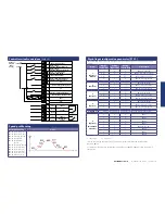
 Step 1  Electrical connections

 Step 2  Motor nameplate data entry

 Step 3  Encoder nameplate data entry


(if an encoder is used)

 Step 4  Motor auto-tune

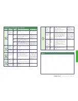
 Control terminal connections


(default)

 Speed profile setup

 Digital input configuration parameter (P1-13)

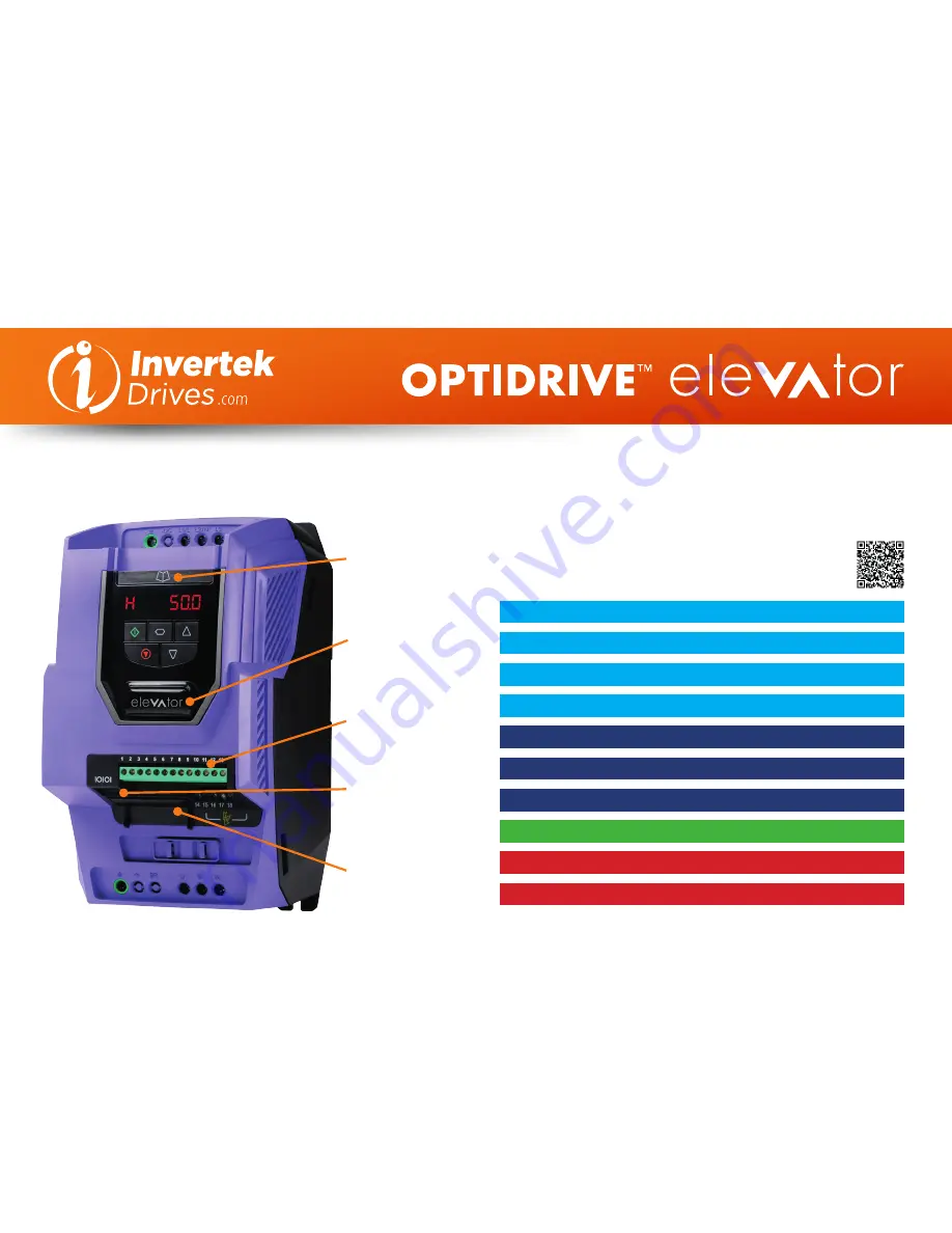
 Optimising & improving travel comfort

 Useful parameters

 Fault messages

Slide out help card 

Quick reference to 
travel curve setup

Back-lit elevator logo 

Logo flashes if the drive 
trips

RJ45 port 

Modbus/CanOpen 
connection

Expansion slot 

Encoder Interface

Pluggable control 
terminals

OPTIDRIVE elevator

   |   Quick Start-up Guide   |   Version 1.0

Please refer to the ‘Optidrive P2 Elevator User Guide’ for 
complete safety and operating instructions, this can be found 
at 

www.invertekdrives.com 

or by scanning this QR code

Summary of Contents for Optidrive Elevator

Page 1: ...13 Optimising improving travel comfort Useful parameters Fault messages Slide out help card Quick reference to travel curve setup Back lit elevator logo Logo flashes if the drive trips RJ45 port Modbus CanOpen connection Expansion slot Encoder Interface Pluggable control terminals OPTIDRIVE elevator Quick Start up Guide Version 1 0 Please refer to the Optidrive P2 Elevator User Guide for complete ...

Page 2: ...7 Enter Voltage value as shown on the motor nameplate Volts Enter Motor Rated Current Enter value into P1 08 Enter Current value as shown on the motor nameplate Amps Enter Motor Rated Frequency Enter value into P1 09 Enter Frequency value as shown on the motor nameplate Hz Enter Motor Rated Speed Enter value into P1 10 Obtained from Motor nameplate The drive will now operate in Rpm Enter Motor pow...

Page 3: ... 1 1 1 P2 08 1 Input High 0 Input Low If 0 the drive will trip on External trip or F Ptc if a motor thermistor fitted and Ptc th has been selected in P2 33 If 0 drive will fast stop using deceleration ramp in time set in P2 25 if P2 25 is zero the drive will coast to stop Speed profile setup Related Parameters Action P1 03 Accel ramp time P1 04 Decel ramp time P2 01 Levelling Speed P2 02 Run Speed...

Page 4: ... is set to low the system response will be slow if too high the system could become unstable and show as Vibration 3 Jerk Felt During stopping Brake coming on too early P4 01 0 1 2 Decrease P3 09 brake apply speed or Use motor Brake control option 2 see 10 6 2 Deceleration time too short P4 01 0 1 2 Increase P3 01 Acceleration S Ramp 1 duration 3 Floor Levelling Short Drive is reaching current lim...

Page 5: ...is free and that no jams blockages or other mechanical faults exist Over voltage on DC bus The value of the DC Bus Voltage can be displayed in P0 20 This fault is generally caused by excessive regenerative energy being transferred from the load back to the drive during braking Increase the deceleration ramp time P1 04 Check a suitable brake resistor is connected to the drive If operating in Vector...

Reviews: