background image


IW-RS212-07


User Manual


Summary of Contents for Cobra IW-RS212-07

Page 1: ...IW RS212 07 User Manual ...

Page 2: ...e Fan Module 12 2 3 1 Removing the Fan Module 12 2 3 2 Installing the Fan Module 13 2 4 Removing and Installing the PSU Module 13 2 4 1 Removing the PSU Module 13 2 4 2 Installing the PSU Module 15 2 5 Removing and Installing the Rear 2 5 HDD For OS 15 2 5 1 Removing the Rear 2 5 HDD 15 2 5 2 Installing the Rear 2 5 HDD 16 2 6 Installing the Slide Rail 17 2 6 1 Identifying the Slide Rail 17 2 6 2 ...

Page 3: ...1 Connecting Expander Through SAS Connectors 22 2 8 2 Connecting LED Cable Front Control Panel and Front USB I O Ports 22 3 Backplane Introduction 23 4 Compatibility Lists 24 5 Q A 25 6 Technical Support 26 ...

Page 4: ...from sources of heat including direct sunlight and radiators It should be kept away from sources of vibration or physical shock The space should be accommodated with a properly grounded wall outlet and with sufficient space to access the power supply cords The operating environment temperature should be around 0 C to 40 C 32 F to 104 F Heed safety instructions Before working with InWin IPC storage...

Page 5: ...per carefully and plug the jumper to cover the jumper pins on the backplane Once you need to remove the jumper grip the jumper and carefully pull without squeezing CAUTION To avoid damage and maintain your safety please read the following terms listed below 1 Do not populate hard drives and turn on the power until the system has stabilized Make sure hard drives and other components are properly co...

Page 6: ... On Off Reset NMI ID SW USB 3 0 x 2 Backplane 1 Mini SAS HD 12Gb s with Expander plus Slim Line x 4 Backplane 2 Mini SAS HD 12Gb s with Expander plus OcuLink x 4 SAS 12G Expander Supports LSI 3x36R Expander Cooling Fan 8038mm PWM Fan x 4 Expansion Slot Low profile PCIe Slot x 7 Material Material SGCC Thickness 1 0mm Rail Kit Supports 28 Tool less Ball bearing Slide Rail Product Dimensions D x W x ...

Page 7: ... SSD Backplane 2 RS212 07 Oculink Backplane Dimension W x H 405mm x 72 3mm Backplane Type Active with Expander Onboard Host Interface 3x SFF 8643 4x SFF 8611 Oculink HDD Interface 12x SAS SATA or 8x SAS SATA and 4x NVMe SSD The actual product is subject to change without prior notice In Win Development Inc reserves the right to make any final modifications Above image is for reference only All har...

Page 8: ...5 1 Product Introduction 1 1 Box Contents When you open the IW RS212 07 box the contents should include the following ...

Page 9: ...pen the chassis it should reflect the diagram s image Rear top cover CRPS redundant or single power supply module 12 x 3 5 tool less HDD trays Front controls and indicators ATX CEB or EEB motherboard PWM fans Max 4pcs Rear 2 5 HDD for OS ...

Page 10: ...r define 3 Power On Off Button with LED Green Solid on System is powered on N A Off System is off 4 Chassis ID Button with LED Blue Solid on Press the button to activate system identification 5 Hard Disk LED Amber Blinking System HDD accessing 6 System Fail LED Amber Solid on System Status Green Solid on System Status 7 LAN LED From top to bottom ranked LAN1 LAN4 Green Blinking Link between system...

Page 11: ...ystem I O Depends on M B Specifications The I O shield should come with the motherboard or provided by motherboard vendors 4 7 Low Profile PCI E Slots The slots support low profile cards The bracket should be removed before using 5 OS HDD This slot is for InWin OS disk backup module optional which supports two 2 5 12G SSDs and features hot swap function ...

Page 12: ...ves faster 2 1 1 Installing a Hard Drive Step 1 Press the release button then pull the handle outward Step 2 Pull both sides of the 3 5 HDD tray outward Place the hard drive into the tray Push both sides of 3 5 HDD tray back Step 3 Insert the HDD tray to the slot Step 4 Push back the lever until it clicks Step 1 Step 2 Step 3 Step 4 Press Pull Insert the HDD tray Push back ...

Page 13: ...he handle outward Step 2 Pull both sides of 3 5 HDD tray outward Pull out the hard drive Push both sides of 3 5 HDD tray back Step 3 Insert the HDD tray to the slot Step 4 Push back the lever until it clicks Step 1 Step 2 Step 3 Step 4 Pull Press Insert the HDD tray Push back ...

Page 14: ...op cover and push the silver buttons on both sides up Step 2 Push the rear top cover backward Step 3 To insert the cover place the cover at the rear and push it to the fitted location Tighten the screw to secure the rear cover Refer to steps 1 2 above Step 1 Step 2 Push Push Release 1 Push 2 ...

Page 15: ...S212 07 s built in fan modules feature a tool less design which makes it easy to maintain 2 3 1 Removing the Fan Module Step 1 Pull the handles up on both sides of the fan Step 2 Pull out the fan module from the fan slot Step 1 Step 2 Press Press Pull Pull ...

Page 16: ...IW RS212 07 has a built in redundant power supply unit With this function the system is capable of still operating if one of the modules fail To replace it the user only needs to release the failed module then insert a functional module 2 4 1 Removing the PSU Module Step 1 Press the release tab of the power supply unit s module at the back Step 2 Pull the module out using the handle Step 1 ...

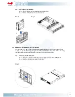
Page 17: ...14 Step 2 Pull ...

Page 18: ...s 2 The two PSU modules output wattage must be the same 2 5 Removing and Installing the Rear 2 5 HDD For OS This slot is for the InWin OS disk backup module optional which supports two 2 5 12G SSDs and features hot swap function 2 5 1 Removing the Rear 2 5 HDD Step 1 Press the release button then pull the handle outward Step 2 Pull out the hard drive Step 3 Insert the HDD tray to the slot Push bac...

Page 19: ...lling the Rear 2 5 HDD Step 1 Press the release button then pull the handle outward Step 2 Place the hard drive into the tray Step 3 Insert the HDD tray to the slot Push back the lever until it clicks Step 1 Step 2 Push Press Pull ...

Page 20: ...ce the quick installation guide inside the slide rail package and follow the instructions to mount the rail onto your cabinet or chassis rack 2 6 2 Removing the Inner Rail and Sliding the Intermediate Rail Back Step 1 Pull out the inner rail until it reaches the stop Release the blue slide tab to unlock Step 2 Continue pulling the inner rail until the second stops Release the white slide tab to re...

Page 21: ...nner rail toward the front until the standoffs snap into place securing the rail to the chassis Step 2 Repeat the same action on the other side Step 3 When removing the inner rail Pull up the latch and slide the inner rail forward Remove the keyhole from the standoff to detach the inner rail Action and in the figure Step 1 2 Step 3 ...

Page 22: ... opposite side of the rail bracket to the front rack of the cabinet Step 4 Hang the front hooks of the outer rail at the front of the rack post holes Pull the rail bracket pins that go into the front post holes on the rack until they click Step 5 The other side of the rail is symmetrical repeat the installation steps 1 4 Step 6 Once you would like to detach the bracket pull outward on the front an...

Page 23: ...to the middle rails on the both sides of the rack Step 4 Push the chassis to the stop position then release the blue slide tab by either pulling the tab forward or pushing the tab back to continue Step 5 Until reaching the second stop position release the blue slide tab again to continue Step 6 Push the chassis into position on the rack completely Make sure that the front end of the chassis is ali...

Page 24: ...ure the pillars on the M B tray which match with the M B fixed points Step 3 Align the motherboard down to the chassis Step 4 Fasten the screws to secure the motherboard in the chassis 2 8 Connecting Cables InWin backplanes with expander board are high performance and are a cost effective solution for supporting Intel Purley platform by adding NVMe support The active backplanes support state of th...

Page 25: ...ation CN2 ID LED ID LED RED BLACK Chassis ID Button with LED CN3 SYSTEM LED SYS LED RED BLACK System Fail LED CN4 ID Switch ID SW RED BLACK Chassis ID Button with LED CN5 Power LED PW LED RED BLACK Power ON OFF Button with LED CN6 LAN 1 LED LAN1 LED RED BLACK LAN LED CN7 HDD LED HDD LED RED BLACK HDD Active LED CN8 Power Switch PW SW RED BLACK Power ON OFF Button with LED CN9 Reset Switch RESET SW...

Page 26: ...ence the backplane user guide to complete the installation Visit InWin website https www in win com en ipc server The download link is at the download section of each product OCuLink Backplane for NVMe Top Side Bottom Side SlimLine Backplane for NVMe Top Side Bottom Side ...

Page 27: ...programming onboard MCU FW JM4 MB Fan For connecting to MB 4 pin fan connector S1 LED Mode Sel For selecting NVMe LED management mode Rear 2 5 HDD BP 4 Compatibility Lists To reach the best performance and avoid system failure InWin strongly recommends users to choose the components from InWin s compatibility list All the components are tested in InWin s lab and assured the components are compleme...

Page 28: ... best performance d Does the chassis support SSDs or flash NVMe drives A Any SSD supports SAS or SATA and 4x NVMe connection can be attached to the InWin IW RS212 07 We recommend referencing InWin s compatibility list to check if your SSD is listed or referencing the information to purchase SSD e Does the chassis support mirrored OS disks A The InWin IW RS212 07 models supports 2 bay 2 5 hot swap ...

Page 29: ...les that you easily buy from many vendors You can buy the verified cable from InWin to eliminate the compatibility issues 6 Technical Support If you need help with installation or troubleshooting you can contact your local InWin rep or send an e mail to InWin s local contacts for technical assistance ...

Reviews: