
2
1
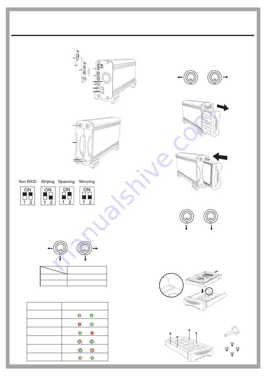
Panel Introduction
Jumper
Key lock
Power Indicator and HDD Access Indicator
To remove the tray, grab the mobile tray firmly
and pull the tray from the housing gently.
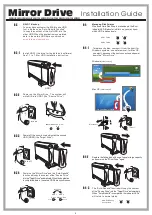
How to Install the SATA HDD
2-1
1-1
1-2
2-2
Installation Guide
Mirror Drive
To install the SATA HDD, simply place the HDD
inside the tray as illustrated below. (A stopper in
the rear of the tray is provided to avoid careless
handling.)
After placing the HDD inside the tray, adjust and
secure the HDD with the provided screwdriver
and four hex-head #6-32 UNC screws.
SATA connector
1. RAID Setting Switch
2. FireWire Connector
3. USB B Connector
4. DC Power Jack (12V/4.16A)
5. Power Switch
6. Cooling Fan
7. Key lock
8. SATA HDD Mobile Tray
9. HDD 1 Status LED
(Green & Red)
10. HDD 2 Status LED
(Green & Red)
1-3
1-4
To insert the tray, grab the mobile tray firmly and push
the mobile tray back into the housing.
A
B
Security status
Locked (Non-removable)
Unlocked (Removable)
Status
Segment
B
A
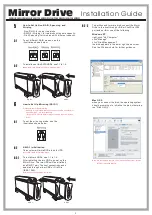
According different statuses, the indicator displays are as followed:
- Non-RAID: for one or two disks
- RAID 0 (Striping): for two disks with same capacity.
- Disk Spanning: for two disks with different capacity.
- RAID 1 (Mirroring): for two disks with same capacity.
1
2
3
4
5
6
9
10
Normal State
HDD 1 Failed
HDD 2 Failed
HDD 1 under Rebuilding
HDD 2 under Rebuilding
HDD Duplicating
is completed
Green
Green
Green
Green
Green
Red
Red
Green
Red/Orange Green
Blinking
Blinking
Green Red/Orange
Blinking
Blinking
Status
Display
A
B
How to Remove and Insert the Mobile Tray
A
A
To unlock the tray, insert the key and push to turn
the lock to Position A.
Note: The key cannot be removed when the lock is in Position A.
HDD1
HDD2
To lock the tray in place, turn the lock back to
Position B.
Note: The key can be removed while the lock is in Position B.
B
B
7
8
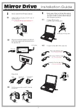
FWBU2SATA35DMR/UF2SATA35DMR/UFISATA35DMR/U2SATA35DMR
FireWire-6pin (only for UF2SATA35DMR)
Bilingual-9pin (only for FWBU2SATA35DMR)
FireWire-6pin + iLink-4pin (only for UFISATA35DMR)
2
1
T-shape screw driver
Hex-head #6-32 UNC
2


