

H
eavy Duty Reader
ELECTRONIC SUPPORT SERVICE
iseozero1
.com
®
i s e o
. c o m
Iseo Serrature s.p.a
Via San Girolamo 13
25055 Pisogne (BS)
ITALY
Tel. +39 0364 8821
iseo@iseo.com
Non contractual document. Subject to change. Cod. 600000E03201 - 10/09/2018
Heavy Duty Reader (EN) - © 2018 Iseo Serrature S.p.a. - www.iseo.com
INSTALLATION GUIDE
1. TECHNICAL SPECIFICATIONS
Wall mounting antivandal heavy duty reader/writer for F9000 keys.
PRODUCT:
- Solid metal antivandal housing: impact protection grade IK10.
- All weather outdoor usage: IP66, IP67 and IP69 protection grade.
- High corrosion resistance: tested for 480 hours in NSS (Neutral Salt Spray chamber).
- Security fixing screws.
- Ability to replace the mechatronic cylinder core.
- No sharp edges (all rounded edges).
- RS485 interface.
- Power supply: by Atlas
- Power consumption: 2W
- Multicolor signaling LEDs (green, blue, red).
- LxDxH = 150 x 90 x 53 mm
FEATURES:
EN60068-2-1, EN60068-2-2, EN60068-2-3, IEC 60529, IEC 62262.
CERTIFICATIONS:
- Operating temperature: -40°C ÷ +80°C
- Storage temperature: -40°C ÷ +80°C
- Humidity: max 93% without condensation
ENVINRONMENTAL CHARACTERISTICS:
2. PACKAGE CONTENTS
Back cover
fixing plate
1x
1x
Adhesive
gasket
Security fixing
screws
4x
Torx TR20 x 100
(M4 x 8)
Cable
gasket
1x
Front cover with
Electronic board
1x
90
150
53
UM = mm
4. DIMENSIONS
40
120
ø
6
26
7
5. ELECTRICAL CONNECTIONS
TX/RX 485 (A)
TX/RX 485 (B)
(10
÷
24 Vdc)
(GND)
Heavy Duty Reader
connector (RS485)
- Wiring cable not included in the kit.
- Recommended cable: Ethernet
cable FTP AWG24 CAT5E (and above
or equivalent data cable).
- Min/max cross-section of the wires:
0.20÷1.5mm
2
(24÷15AWG).
- Min/max cable diameter: 3÷7mm
- Max length: up to 500mt
R
6. ELECTRICAL CONNECTIONS: ATLAS TYPE AND CONNECTORS
Wall fixings not provided in the kit. The installator must choose the most suitable fixings according to the
wall type and material. ISEO recommends to install the Heavy Duty Reader in a concerete wall by M10 steel
anchors with M6 bolts.
Minimum recommended traction load for anchors: 150Kg.
Maximum bolts diameters 6mm.
Maximum bolts head dimension: 14mm diameter x 6mm thickness.
1
2
R = 120 ohm - 1/4 W
(Supplied with the reader)
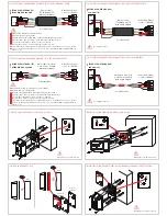
3.1 WARNINGS
Read this manual prior to use the device in order to ensure a safe and proper use.
Preserve this manual as future reference.
The installation of the device requires the intervention of qualified staff, adequately trained by ISEO.
The instructions should be carefully followed during the use of the product. These instructions should be
passed on by the installer to the user.
No modifications of any kind are permitted, except for those described in these instructions.
The product must be destined only for the use for which it is expressly designed and therefore as an heavy duty
reader and writer unit for civil and industrial locations. Any other use is considered improper and dangerous.
Keep the
Front cover
inside its box during the installation of the
Back cover fixing plate
, to prevent
drilling residues from entering inside the
Electronic board
.
Use the
Adhesive gasket
only in case of not-straight or no flat wall. If the
Adhesive gasket
is required,
take care to uniformly apply it to seal the reader to the wall, in order to avoid any water penetration.
Check if the
Back cover gasket
is correctly fitted in the slot. If not re-position it correctly in order to avoid
any water penetration.
Do not enlarge, damage or modify the
Cable gasket
, failure to do that it could compromise the water
sealing. Use a max cable diameter of 7mm to ensure the cable passage through the cable gasket hole.
Check the
Wiring cable
perfectly fits inside the
Cable gasket
hole without leaving any space that could
allow water penetration. Use a min cable diameter of 3mm to ensure the cable gasket impermeability.
3. WARNINGS
Back cover
gasket
ATLAS DIN
ATLAS STANDARD (STD)
ATLAS PLUS
CH1
4
3
2
1
(GND)
CH2
4
3
2
1
5
6
CH2
4
3
2
1
(GND)
CH1
4
3
2
1
(GND)
ø
min.3mm
max.7mm
ø
1x
R = 120 ohm - 1/4 W
(Connect to ATLAS)


