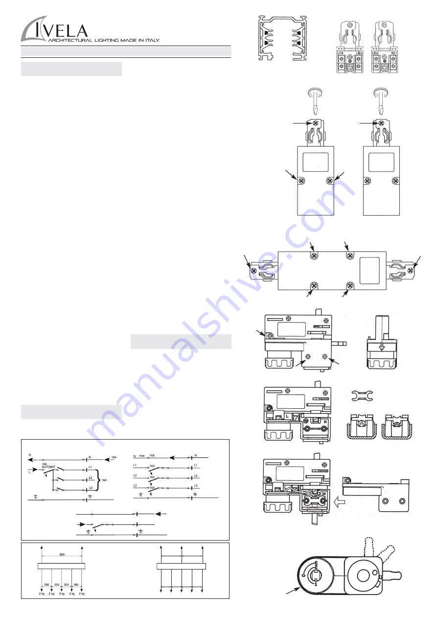
I - BINARIO TRIFASE art. 7511
440V 16A CL1
Il binario ed i suoi componenti, compresi gli adattatori in cIasse 1
non sono intercambiabili con sistemi a binario di classe III o con
accessori che non riportino il Marchio di Qualità. E’ responsabilità
dell’utente assicurare la compatibilità elettrica, meccanica e
termica tra i sistemi a binario e gli apparecchi ad esso connessi.
Interventi sull’impianto elettrico sono consentiti solo a personale
qualificato legalmente riconosciuto.
Montaggio
Installare il bianario tramite i fori già predisposti sul profilato
oppure utilizzando gli accessori art. 7606 - Kit di sospensione
oppure art. 7607 - Kit soffitto, coi limiti di carico indicati nella fig. 5.
Connettori di alimentazione art. 7652 Dx art. 7652 Sx 440V
16A
Collegamento:
Aprire il vano portacontatti, svitando le due viti come indicato nella
fig. 2. Sfondare la prerottura per il passaggio del cavo, collegare i
conduttori facendo attenzione alla dicitura N L1 L2 L3 T e
successivamente bloccarli tramite il ponticello fermacavo.
Montaggio:
Inserire il connettore nel binario facendo attenzione al corretto
orientamento (Dx o Sx) e quindi bloccarlo con la vite A come da
fig. 2.
Alimentazione centrale art. 7653 440V 16A
Collegamento:
Aprire il vano portacontatti svitando le quattro viti come indicato in
fig. 3. Sfondare la prerottura per il passaggio del cavo, collegare i
conduttori facendo attenzione alla dicitura N L1 L2 L3 T e
successivamente bloccarli tramite il ponticello fermacavo.
Montaggio:
Inserire il connettore nel binario facendo attenzione al corretto
orientamento (Dx o Sx) e quindi bloccarlo con le viti A come da
fig. 3.
Adattatore per binario art. 7601 250V 6A
Collegamento:
Svitare le tre viti come da fig. 4A. Inserire il cavo dell’apparecchio
attraverso il foro della bussola di rotazione e fissarlo con
l’apposito ponticello come da fig. 4D. Collegare i tre conduttori
facendo attenzione alla dicitura L N T come da fig. 4B e 4C-
Rimontare e fissare il coperchio. L’uso è limitato al sistema binario
specificato
Montaggio:
Inserire l’adattatore nel binario con la leva D orientata come da
fig. 6 posizione F e quindi bloccarlo ruotandola dalla posizione F
alla posizione G. Selezionare quindi la fase desiderata tramite la
manopola E come da fig. 6. Non applicare apparecchi di peso
superiore a 50N.
Montaggio a parete
Nel caso del montaggio a parete con binario in posizione
orizzontale, non applicare all’adattatore un momento flettente
superiore ad 1Nm. Nel caso di montaggio a parete con binario in
posizione verticale, la scanalatura di guida del profilato del binario
deve essere a destra; non applicare all’adattatore un momento
flettente superiore a 2Nm.
Attenzione!
Per l’installazione di faretti aventi un peso superiore
a 50N o che superano i momenti flettenti rispettivamente di 1Nm
e 2Nm, utilizzare l’adattatore meccanico art. 7625.
Installare/utilizzare il prodotto in modo diverso da quanto
prescritto comporta la perdita delle caratteristiche
tecniche/meccaniche, di conseguenza il decadimento della
garanzia.
UK - THREE-PHASE TRACK ART. 7511
440V 16A CL1
The track and its components, including adapters in Class I, are
not interchangeable with track systems in Class III or with
accessories which do not show the Quality Mark. The
responsibility to ensure the electric, mechanical and termic
compatibility between track systems and connected fittings rests
with the user. All fittings must be connected by a qualified
electrician.
Installation
Install the track by the holes on its surface or by using the
accessories art. 7606 - suspension kit, or art. 7607 - ceiling kit,
respecting the load limits shown in pic. 5.
Live-ends art. 7652 Dx art. 7652 Sx 440V 16A
Connection:
Open the case with contacts by unscrewing the two screws as in
pic. 2. Break the bottom of the suitable hole to let the cable pass
through. Connect the wires paying attention to the caption N L1
L2 L3 T and then fix them by the strain relief.
Installation:
Insert the live-end into the track, paying attention to the right
orientation (Dx or Sx) and then fix it by the screw A, as in pic. 2.
Mean connector art. 7653 440V 16A
Connection:
Open the case with contacts by unscrewing the four screws as in
pic. 3. Break the bottom of the suitable hole to let the cable pass
through. Connect the wires paying attention to the caption N L1
L2 L3 T and then fix them by the strain relief.
Installation:
Insert the connector into the track, paying attention to the right
orientation (Dx or Sx) and then fix it by the screws A as in pic. 3.
Track adapter art. 7601 250V 6A
Connection:
Unscrew the three screws as in pic. 4A. nsert the cable of the
fitting into the rotation washer and fix it by the suitable device, as
in pic. 4D. Connect the three wires paying attention to the caption
L N T , as in pic. 4B and 4C. - The use is limited to specified rail
system
Installation:
Insert the adapter into the track with the lever D oriented as in pic.
6, position F, and then fix it turning it from the position F to the
position G. Select the phase you wish by using the handgrip E, as
in pic. 6. Do not install fittings with load over 50 N .
Wall mounting
In case of wall mounting with track in horizontal position, do not
apply a moment of flexure over 1 Nm to the adapter. In case of
wall mounting with track in vertical position, the guide groove of
the track surface must be on the right. Do not apply a moment of
flexure over 2 Nm to the adapter.
Warning!
To install fittings weighing over 50 N, or exceeding the
moments of flexure of respectively 1 Nm and 2 Nm use the
mechanical adapter art. 7625.
Install/use the product other than as prescribed involves the loss
of technical/mechanical characteristics, consequently invalidate
the warranty.
F - RAIL TRIPHASE’ ART. 7511
440V 16A CL1
Le rail et ses composants, inclus les adaptateurs en CI. I ne sont
pas interchangeables avec des systèmes rail en CI. III ou avec
des accessoires qui n’ont pas le Marquage de Qualité. C’est
résponsabilité de l’utilisateur assûrer la compatibilité électrique,
mécanique et thermique entre les systèmes rail et les appareils
branchés. Toute intervention sur l’installation èlectricque est
consentie seulement à des électriciens qualifiés.
Montage
Installer le rail par les trous présents sur le profilé ou utilisant les
accessoires art. 7606 - kit suspension, ou art. 7607 - kit plafond,
avec les limites de charge indiquées dans la fig. 5.
Connecteurs d’alimentation art. 7652 Dx art. 7652 Sx 440V
16A
Branchement:
Ouvrir le boîtier des contacts, dévissant les deux vis comme dans
la fig. 2. Percer la pre-ouverture prévue pour le passage du câble;
FIG. 1
FIG 2
FIG 3
FIG 4A
FIG 4B
FIG 4C
FIG 6
FIG 4D
F
E
G
D
A
A
DX
SX
FIG. 2
A
A
DESTRO
RIGHT
SINISTRO
LEFT
max 0,25 N/m
max 0,25 N/m
200
200
200
200
10 kg
10 kg
10 kg
10 kg
10 kg
400
400
16A
N
L1
N
L
16A
Automat
SCHEMA ELETTRICO
CARICO MASSIMO
FIG. 5
LKM