


Reviews:
No comments
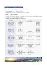
Related manuals for JAM60S01 PR Series

SFE Series
Brand: NDS Pages: 16

LG N2T-J5 Series
Brand: LG Pages: 16

LG270N1C(W)-G3
Brand: LG Pages: 12

LG N1C-G4 Series
Brand: LG Pages: 18
LG N1C-A3 Series
Brand: LG Pages: 14

LG280N1C-G4
Brand: LG Pages: 14

LG***N1CK-A3
Brand: LG Pages: 14

LG S1C-A3 Series
Brand: LG Pages: 12

LG N1C(W)-E6 Series
Brand: LG Pages: 18

LG315Q1K-A5
Brand: LG Pages: 12

LG365S1C-U6
Brand: LG Pages: 17

LG220P1C
Brand: LG Pages: 116

SP-5400
Brand: Schumacher Electric Pages: 20

WM Touch
Brand: powersoft Pages: 12

1931T
Brand: Nexcom Pages: 130

Innova 30i-E
Brand: Fagor Pages: 48

iXP2-08 A Series
Brand: LS Pages: 2

eXP20-20-TTA/DC
Brand: LS Pages: 2


