
1
/
8
F5 Control Box Manual Book
SAFETY INSTRUCTION
·
Before using this product, please read the product manual and the mechanical manual of the
matching sewing machine.
·
This product must be installed or operated by professionally trained personnel.
·
Please keep away from arc welding equipment as far as possible to avoid misoperation caused
by electromagnetic wave interference with the controller.
·
Please do not use it in places where the room temperature is above 45
°
or below 0
°
.
·
Please do not use in places with humidity below 30% or above 95% or with dew&acid mist.
·
When installing the control box and other components, please turn off the power and unplug
the power plug first.
·
In order to prevent interference or leakage accidents, please do a good job in grounding
engineering. The grounding wire of the power line must be firmly and effectively connected
with the earth.
·
All spare parts for maintenance shall be provided or approved by the company before use.
·
Before carrying out any maintenance action, the power supply must be turned off and the
power plug must be unplugged. There is a danger of high voltage in the control box. You must
turn off the power for five minutes before opening the control box.
1.
Installation
1.1
Product specification
220V Control box specification
Power voltage
AC 220±20% V
Power frequency
50Hz/60Hz
Max output power
550W
110V Control box specification
Power voltage
AC 110±20% V
Power frequency
60Hz
Max output power
550W
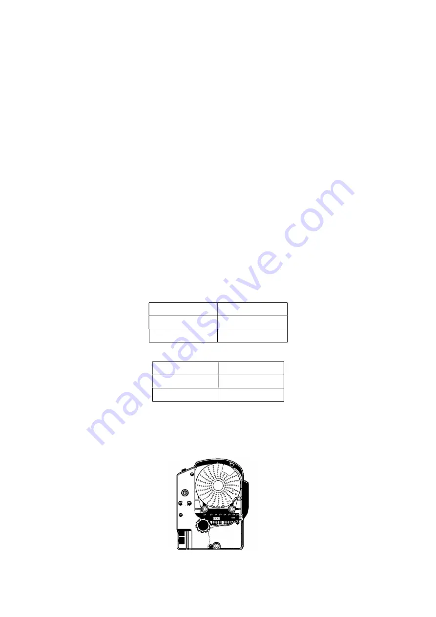
1.2
Connection of interface plug
Insert the connecting plugs of the pedal and the head into the corresponding socket
behind the control box. The name of each socket is shown in Figure 1-2. After connection,
please check whether the plug is firmly inserted.
○
1
○
2
Figure 1-1 Control box diagram