background image

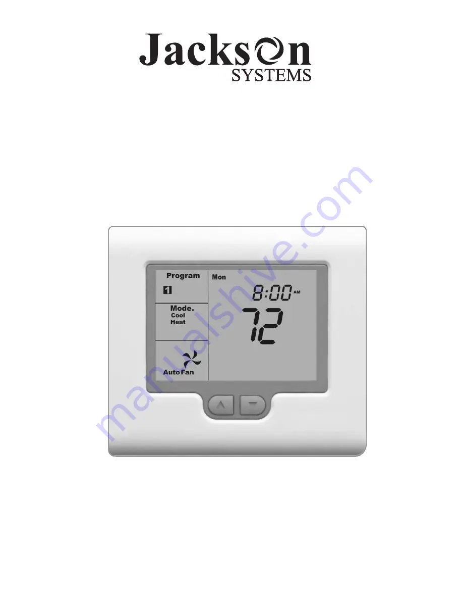
Comfort System T-32-P Universal Thermostat

Installation Manual

TM

Version 3.0

O

Summary of Contents for Comfort System T-32-P

Page 1: ...Comfort System T 32 P Universal Thermostat Installation Manual TM Version 3 0 O...

Page 2: ...afe and efficient manner The T 32 P thermostat is intuitive reliable and easy to install Using a common sense approach to the installation will ensure this product is installed properly and to the cus...

Page 3: ...e T 32 P be aware that drafts may travel down wall cavities and enter the back of the thermostat through the control wire hole in the wall It is important to seal the hole to prevent any drafts that m...

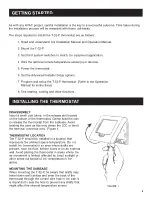
Page 4: ...er seating of the thermostat connecting pins to the terminal blocks Do not over tighten the terminal screws INSTALLING THE THERMOSTAT MOUNTING HOLES FIGURE 2 TERMINAL DESIGNATIONS Based on the T 32 P...

Page 5: ...d out Typical settings might be 30 F Low Balance Point and 55 F High Balance Point High and low balance point control can also be used in conventional heat pump applications Advanced Installer Setting...

Page 6: ...switch to the OFF position factory default For B reversing valve energize in heating set the switch to the ON position Switch 5 is used to configure the fan operation For gas systems set the switch to...

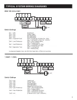
Page 7: ...er Menu Set FN H for Heat Only or FN C for Cool Only TYPICAL SYSTEM WIRING DIAGRAMS W2 Y2 W1 O B Y1 G R 24 24C B A T T HEAT 1 RELAY FAN 1 RELAY MODBUS TT TERMINALS LINE 24 V COMP 1 RELAY 1 HEAT 1 COOL...

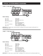
Page 8: ...EAT 2 RELAY 24 V TYPICAL SYSTEM WIRING DIAGRAMS 2 HEAT 1 COOL HEAT PUMP Switch Settings Sw1 ON Heat Pump Sw2 OFF Single Stage Sw3 OFF Conventional Heat Pump Sw4 Reversing Valve OFF O ON B Sw5 ON Therm...

Page 9: ...VALVE FAN 1 RELAY MODBUS TT TERMINALS LINE COMP 1 RELAY COMP 2 RELAY AUX HEAT 24 V TYPICAL SYSTEM WIRING DIAGRAMS 2 HEAT 1 COOL DUAL FUEL Switch Settings Sw1 ON Heat Pump Sw2 OFF Single Stage Sw3 ON...

Page 10: ...THE ADVANCED INSTALLER SETTINGS MENU The T 32 P contains factory defaults for all Advanced Installer Settings Depending upon the user and equipment application some settings may need to be changed To...

Page 11: ...nction FO 2 Constant fan during occupied mode Fan must be set to ON for this function to work F increments FP 0 Fan Purge Adjustable from 0 5 minutes after any call FN Mode FN Manual Changeover FN A A...

Page 12: ...is a single sensor that can be used indoors or outdoors The T 32 S2 contains two sensors A combination of both sensors can be used for indoor temperature averaging to simplify wiring When the T 32 S1...

Page 13: ...Advanced Installer menu setting must be TT RS to use this feature Figure 7 W2 G3 Y2 G2 W1 O B Y1 G1 R 24 24C B A T T T 32 S1 SENSOR OPTIONAL SWITCH FIGURE 7 W2 G3 Y2 G2 W1 O B Y1 G1 R 24 24C B A T T T...

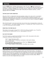
Page 14: ...CD 1 in the Advanced Installer menu After exiting the menu a wrench icon will flash on the LCD This is to remind you that once testing is completed the time delays need to be re initiated by setting...

Page 15: ...change CD 1 to CD 0 in the Advanced Installer menu This will be confirmed when the flashing wrench icon no longer appears on the LCD The T 32 P contains a simple factory Test Mode that can confirm re...

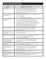
Page 16: ...led and time delays are overridden Change CD 1 to CD 0 in the Advanced Installer menu Outdoor temperature does not Check wiring to outdoor sensor Make sure that TT OA in display Dashes appear the Adva...

Page 17: ...tat use an ohm meter or multimeter to measure the resistance of the sensor Measure at the end of the wires that will connect to the thermostat Confirm the resistance value within 5 to the temperature...

Page 18: ...esistance 10k 77 F Tolerance 3 77 F Stage Delays Minimum temperature change over time Timed Upstage Delay 5 90 minutes Short cycle Delay Off to 4 minutes Display Resolution 1 F Control Range 41 F to 1...

Reviews: