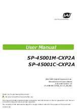
background image

SP-45001M-CXP2A

SP-45001C-CXP2A

45M CMOS Digital Progressive Scan


Monochrome and color Camera


Document Version: 1.

3

SP-45001MC-CXP2A_Ver.1.

3

_

Oct

.2021

User Manual

Thank you for purchasing this product.

Be sure to read this manual before use.

This manual includes important safety precautions and instructions on how to operate the unit. Be sure 

to read this manual to ensure proper operation.
The contents of this manual are subject to change without notice for the purpose of improvement.
© 202

1

 JAI

Summary of Contents for SP-45001C-CXP2A

Page 1: ...021 User Manual Thank you for purchasing this product Be sure to read this manual before use This manual includes important safety precautions and instructions on how to operate the unit Be sure to read this manual to ensure proper operation The contents of this manual are subject to change without notice for the purpose of improvement 2021 JAI ...

Page 2: ...omply with the limits for a Class B digital device pursuant to Part 15 of the FCC Rules These limits are designed to provide reasonable protection against harmful interference in a residential installation This equipment generates uses and can radiate radio frequency energy and if not installed and used in accordance with the instructions may cause harmful interference to radio communications Howe...

Page 3: ... Control function Sequencer Function Pulse Generator Counter And Timer Control Function Lens control Transfer camera control commands Non Volatile Flash Memory 56 21 22 Setting List 57 23 Feature Properties 58 24 26 Miscellaneous 69 27 69 28 70 30 73 31 74 32 34 75 35 Troubleshooting Specifications Spectral Response Dimensions Comparison of the Decibel Display and Multiplier Display User s Record ...

Page 4: ...notes SP 45001M CXP2A SP 45001C CXP2A 58 23 31 43 44 46 47 60 20 21 22 32 33 34 35 61 17 36 37 39 64 38 65 26 27 28 29 30 60 65 39 40 64 10 11 12 13 24 25 62 54 55 67 18 67 51 52 67 48 49 59 53 53 42 43 66 41 66 45 60 56 68 50 68 DeviceControl ImageFormatControl AcquisitionControl AnalogControl AutoLevelControl ImagingControl LUTControl DigitalIOControl CounterAndTimerControl UserSetControl Sequen...

Page 5: ...inistration of the control of Pollution by Electronic Information Products known as China RoHS The table shows contained Hazardous Substances in this camera mark shows that the environment friendly use period of contained Hazardous Substances is 15 years SP 45001M CXP2A SP 45001C CXP2A 5 ...

Page 6: ...nto surrounding pixels This blooming phenomenon can be seen in the image but does not affect the operation of the camera Fixed pattern noise When shooting dark objects in high temperature conditions fixed pattern noise may occur throughout the entire video monitor screen Defective pixels Defective pixels white and black pixels of the CMOS image sensor are minimized at the factory according to ship...

Page 7: ...ve pixels 8192 h x 5460 v Pixel size is 3 2μm x 3 2μm Various integrated functions HDR High Dynamic Range Frame Integration Supports video output modes 8 bit 10 bit 12bit and 14 bit 14 bit output is only available for some integrated functions Interface CoaXPress v2 0 CXP12 12 5Gbps Micro BNC 2 High speed scanning Maximum frame rate Full resolution 8192 x 5460 38 fps 8K resolution 8192 x 4320 48 f...

Page 8: ...d the supported lens types POWER TRIG LED Indicates the power and trigger input status LED status and camera status LED Light Status POWER TRIG LED Lit amber Camera initializing Lit green Camera in operation Blinking green During operation in trigger mode trigger signals are being input The blinking interval is not related to the actual input interval of the external trigger SP 45001M CXP2A SP 450...

Page 9: ...uivalent is used SP 45001M CXP2A SP 45001C CXP2A The CxpLink Configuration supported by this camera is as follows CXP12_X2 CXP12_X1 CXP6_X2 CXP6_X1 The CxpLink Configuration CXP12_X2 CXP12_X1 can only be used with CXP 2 0 The CoaXPress frame grabber board used must support CXP 2 0 When using a CoaXPress frame grabber board that does not support CXP 2 0 set the CxpLinkConfiguration setting to CXP6_...

Page 10: ...PoCXP Be sure to use a power supply that can support the maximum power consumption of this camera CXP 1 is the only channel for PoCXP Pin No Input Output Signal Description 1 GND GND 2 Power In DC In DC 10 V 25 V 3 GND GND 4 NC 5 In Opto In 1 6 In Opto In 1 7 Out Opto Out 1 8 Out Opto Out 1 9 Out TTL Out 1 Line 1 10 In TTL In 1 Line 4 11 Power In DC In DC 10 V 25 V 12 GND Line 5 Line 2 Compatible ...

Page 11: ...diagram reference example Recommended external output circuit diagram reference example 1 2 Opto In 1 1 Pin6 Opto In 1 2 Pin5 Opto In 1 Digital I O Control Technical notes OPTO In circuit characteristics SP 45001M CXP2A SP 45001C CXP2A 11 ...

Page 12: ...ne Voltage Please note that the recommended load resistance of Opto output is 10 kΩ rated 1 10 W or more The 270 Ω resistor shown in the circuit diagram is the MINIMUM resistance that should be used The response speed from On High to Off Low depends on the voltage applied to Opto output and the value of the load resistance Higher load resistance results in slower response If the response at 10 kΩ ...

Page 13: ...unting the camera directly to a wall or other structural system Camera locking screw holes M3 3 mm depth Use these holes when mounting the camera directly to a wall or other structural system Digital I O Control Pin No Input Output Signal Description 1 Out TTL Out 2 Line 8 2 N C 3 In TTL In 2 Line 10 4 N C 5 GND GND 6 DC Out LENS Power DC9V 7 Out RS232C Tx 8 Input RS232C Rx 9 GND GND 10 GND GND Fo...

Page 14: ... for use Step 3 Verifying the Connection between the Camera and PC Set settings and display image using suitable tool for CXP frame grabber board Step 4 Adjusting the Image Quality Refer to the procedures for adjusting the gain white balance and black level as examples and adjust the image quality Step 5 Saving the Settings Save the current setting configurations in user memory SP 45001M CXP2A SP ...

Page 15: ...XP 2 CXP 2 CoaXPress cable Direct connection or MP 42 tripod adapter plate When mounting the camera directly to a wall or other device use screws that match the camera locking screw holes on the camera M3 depth 5 mm Use the supplied screws to attach the tripod adapter plate CXP cable Connect the CXP cable to the CXP connector on the camera and frame grabber board The number of cables to connect de...

Page 16: ...being supplied to the camera by checking the rear LED When properly turned on Lit green For details on how to read the LEDs see LED status and camera status in the Parts Identification section Initialization of the camera is not complete until connection with the host is established If the power trigger LED does not switch to green within minutes of supplying power check the CXP cable and other co...

Page 17: ... are configured by multipliers The DigitalRed digital R gain and DigitalBlue digital B gain can be set to a value from x0 447 to the ADigitalAll master gain value The resolution is set in 0 000122 steps Values are configured by multipliers Adjust the white balance using the automatic adjustment function Automatic white balance adjustment 1 Place a white sheet of paper or similar object under the s...

Page 18: ...alues are stored in Default and cannot be overwritten UserSet1 UserSet2 UserSet3 DefaultSet Working Set Memory Flash Memory RAM 3 Select UserSetSave and click Execute UserSetSave Command The current setting values are saved as user settings User Set Control To load user settings 1 Stop image acquisition User settings can only be loaded when image capture on the camera is stopped 2 Select the setti...

Page 19: ...nformation see the Event Control topic CXP Link Sharing Function This function allows a camera to connect to multiple PCs For more information see the CXP Link Sharing topic Heartbeat Function The camera periodically sends signals to the PC to verify that the connection is valid When connected to a CXP 2 0 compatible FG board and the CxpVersionUsed register is set to 2 0 the Heartbeat function is ...

Page 20: ...art Acquisition Stop AcquisitonFrameCount This camera has three Acquisition modes SingleFrame MultFrame Continuous Use AcquisitionControl settings to perform operations and settings for image capture SingleFrame MultiFrame Continuous When the AcquisitionStart command is executed one frame of image is captured When the AcquisitionStart command is executed the number of frames set in AcquisitonFrame...

Page 21: ...igure the settings described in Trigger Control Actual Exposure Times Acquisition Control This camera has three Exposure modes Off Timed TriggerWidth Use AcquisitionControl settings to perform operations and settings for exposure The minimum exposure time that can be set for each operation mode and CXP mode is as follows The actual exposure time will be shorter than the time set for this camera Op...

Page 22: ... after receiving the trigger signal until the trigger is enabled Acquisition Start Acquisition Stop When using FrameStart trigger If AcquisitionStart is executed and the AcquisitionStop command is not executed if a FrameStart trigger is received one frame is acquired Frame Start Frame Start Frame Start The source signals that can be set for the trigger are as follows Acquisition Control TriggerSel...

Page 23: ...on ReverseX 0 False ReverseY 0 False BayerRG ReverseX 0 False ReverseY 1 True BayerGB ReverseX 1 True ReverseY 0 False BayerGR ReverseX 1 True ReverseY 1 True BayerBG 2 14bit output is available only in HDR Linear mode and FrameIntegration Exposure mode Image Format Control Note When using 12bit PixelFormat in normal operation mode Histogram values may be missing In this case please using VideoPro...

Page 24: ...ontrol to set the digital input output Select input or output in LineSelector you can check LineMode LineFormat and set LineInverter You can also check the status of each digital I O as shown in the table below with LineStatusAll LineMode LineFormat LineInverter LineStatusAll Line1 Output TTL True False bit0 DC IN TRIG IN connector 12 pin round Line2 Output OptoCoupled True False bit1 DC IN TRIG I...

Page 25: ...an be set Off AcquisitionActive FrameActive ExposureActive FVAL LVAL PulseGenerator0 PulseGenerator1 PulseGenerator2 PulseGenerator3 UserOutput0 UserOutput1 UserOutput2 UserOutput3 Line4 Line5 Line7 Line10 Nand0Out Nand1Out Low High AcquisitionTriggerWait FrameTriggerWait Line1 Line2 Line4 Line5 Line7 Line8 Line10 Nand0In1 Nand0In2 Nand1In1 Nand1In2 TimestampReset Digital I O Control SP 45001M CXP...

Page 26: ...he Pixel Format that can be used and the functions that can be used at the same time Each Imaging Control mode and Pixel Format Functions available at the same time as each Imaging Control mode FrameIntegrationMode Frame FrameIntegrationMode Exposure HDR Linear HDR Knee VideoProcess BypassMode Bayer8 Bayer10 Bayer12 Bayer14 Mono8 Mono10 Mono12 Mono14 FrameIntegrationMode Frame FrameIntegrationMode...

Page 27: ...rame image and acquire by changing image sensor analog gain to low and high 2 An image captured with low gain is increased Digital Gain 3 Two images are combined into one frame of 14bit image data 4 Output In Linear mode the synthesized 14 bit image is output as it is In Knee mode the synthesized 14bit image is Knee converted and output in 8bit 10bit or 12bit image HDRKneePoint HDRKneeSlope can be...

Page 28: ...e SP 45001M CXP2A SP 45001C CXP2A PixelFormat Width Height Maximum frame rate fps 8192 5460 16 8192 4320 20 4096 2728 32 8192 5460 16 8192 4320 20 4096 2728 32 8192 5460 16 8192 4320 20 4096 2728 32 CXP12 2 Mono8 Bayer8 Mono10 Bayer10 Mono12 Bayer12 PixelFormat Width Height Maximum frame rate fps 8192 5460 16 8192 4320 20 4096 2728 32 CXP12 2 Mono14 Bayer14 28 ...

Page 29: ...ation Frame mode works in Trigger mode only Imaging Output Average frame Average frame Average frame 2 8 frams Imaging Control Maximum Frame Rate Reference The table below shows the maximum frame rate in Frame Integration Frame mode The maximum frame rate differs for each Frame Integration Frame Number Theoretical value Note SP 45001M CXP2A SP 45001C CXP2A 2 3 4 5 6 7 8 8192 5460 5 7 3 8 2 8 2 3 1...

Page 30: ...ation Exposure1 and Frame Integration Exposure2 Frame Integration Exposure mode works in Trigger mode only Add Add Add Add Exposure Time 1 Exposure Time 2 Imaging Output Exposure Imaging Control Note Exposure Time 2 Exposure Time 2 Exposure Time 2 Exposure Time 1 Exposure Time 1 Exposure Time 1 Maximum Frame Rate Reference The table below shows the maximum frame rate in Frame Integration Frame mod...

Page 31: ... The following functions can be used in video process bypass mode AnalogBaseGain BlemishCompensation BinningVertical BinningHorizontal BinningVertical and BinningHorizontal work in Average mode only Functions available in VideoProcessBypassMode Functions unavailable in VideoProcessBypassMode Gain Gamma Shading Knee Enhancer BlackLevel LUT BalanceWhiteAuto GainAuto SequencerGain SequencerBlackLevel...

Page 32: ...Format Frame Period A usec Period From Trigger start edge to Exposure start B usec Mono8 26247 41 4 Mono10 31153 41 4 Mono12 31153 41 4 BayerRG8 26247 41 4 BayerRG10 31153 41 4 BayerRG12 31153 41 4 Mono8 26247 41 5 Mono10 31153 41 4 Mono12 31153 41 5 Vertical Binning On Mono8 26247 41 5 Mono10 31153 41 4 Mono12 31153 41 4 Mono8 26247 41 5 Mono10 31153 41 4 Mono12 31153 41 5 Binning Off Horizontal ...

Page 33: ...od From Exposure end to next Trigger Start D usec Mono8 26667 41 4 41 4 26541 Mono10 31847 41 4 41 4 31727 Mono12 31847 41 4 41 4 31722 BayerRG8 26667 41 4 41 4 26541 BayerRG10 31847 41 4 41 4 31727 BayerRG12 31847 41 4 41 4 31722 Mono8 26738 41 4 41 4 26618 Mono10 31949 41 4 41 4 31823 Mono12 31847 41 4 41 4 31727 Mono8 26667 41 4 41 4 26547 Mono10 31949 41 4 41 4 31823 Mono12 31949 41 4 41 4 318...

Page 34: ... rate in normal mode Theoretical value SP 45001M CXP2A SP 45001C CXP2A PixelFormat Width Height Maximum frame rate fps 8192 5460 38 8192 4320 48 4096 2728 76 8192 5460 32 8192 4320 40 4096 2728 64 8192 5460 32 8192 4320 40 4096 2728 64 Mono8 Bayer8 Mono10 Bayer10 Mono12 Bayer12 CXP12 2 34 ...

Page 35: ... μs that is longer than the maximum exposure time μs calculate the frame rate Hz using the following formula Frame rate Hz 1 Target exposure time μs 14 LinePeriod μs 1 x 1000000 Calculate the maximum frame rate approximate About Height in MultiROI mode If there is an unused area in the vertical direction between the specified areas add 8 to the total height of the areas to be used to obtain the He...

Page 36: ...B 0dB 24dB 7dB 15dB 7dB 15dB x 16 x 1 0 15dB 15dB In SP 45001M CXP2A adjust the AnalogAll master gain setting Digital All 0dB 24dB x 16 x 1 0 Analog Control Automatic Gain Level Control Set GainAuto to Continuous to control the gain level automatically When GainAuto is set to Continuous you can configure the conditions for automatic adjustment in detail When GainAuto is set to Continuous automatic...

Page 37: ... white balance has been adjusted in advance for specific color temperature lighting It is possible to select form the following five presets Color temperature for preset 4000K 4600K 5600K 6500K 7500K Color temperature 5000K 4000K 3000K 2000K 6000K 7000K 8000K natural white cool white sunshine color daylight color warm white Incandescent lamp Candle fire Sun light sunrise sunset Sun light noon Fluo...

Page 38: ... operation ASC auto shutter operation AGC Max AGC operation Max to min user specified Fixed at min gain value ASC operation Max to min user specified Fixed at min ASC value Fixed at max ASC value Operation during change from dark to bright Operation during change from bright to dark To use the ALC function Set GainAuto or ExposureAuto or both to Continuous mode Configure the minimum value maximum ...

Page 39: ...an be used to correct the camera signals with an opposite direction curve and produce a display that is close to linear To use the gamma function Configure the settings as follows You can use the LUT function to configure a curve with more detailed points For details see Lookup Table LUT Analog Control LUT Control Note 0 0 2 0 4 0 6 0 8 1 0 1 2 Example of the light emitting properties of the monit...

Page 40: ...ue 1 LUTValue 2 Index256 LUTValue 256 0 4095 SP 45001C CXP2A only LUT Control Item Setting value selectable range Description LUTMode LUT Use LUT LUTSelector Red Green Blue Select the LUT channel to control LUTIndex 0 256 Select the LUT index to configure Indexes represent the possible pixel values captured on the sensor from the lowest value Index 0 to the highest Index 256 For example Index 0 re...

Page 41: ...mory To check the number of interpolated pixels after automatic detection You can check the number of pixels interpolated via automatic detection by loading the BlemishNum data Manual configuration 1 Select the index in BlemishCompensationIndex You can select from 1 to 3183 However configure the indexes in order starting with the smallest index If you skip indexes while configuring settings interp...

Page 42: ... to the center of the screen H V This function can be used even when the effective image area is limited an area with both Width and Height set to more than 128 must be configured by the ROI function In such cases the correction area is included in the image area configured by the ROI For a full image the number of correction blocks is 64 H 43 V blocks and calculation errors in the correction data...

Page 43: ...If the area in the screen with the highest brightness level is 175 LSB or less during 10 bit video output proper correction is not possible When using the image flip function ReverseX ReverseY set both ReverseX and ReverseY to Off and execute calibration If the image flip function is enabled shading correction will not be performed correctly After executing calibration set to enable the image flip...

Page 44: ...s follows JAI OffsetX Width OffsetY Height 8192 Width Max 5460 Height Max JAI OffsetX Width OffsetY Height 4096 Width Max 2730 Height Max ROI Function Single ROI Image Format Control Without Binning BinningHorizontal 1 BinningVertical 1 With Binning BinningHorizontal 2 BinningVertical 2 Scanning range Scanning range Width pixels Height lines BinningHorizontal Off 128 to 8192 step 128 BinningVertic...

Page 45: ... and MultiRoiHorizontalEnableNumber Example JAI ROI Function Multi ROI OffsetY 0 OffsetY 1 OffsetX 0 OffsetX 1 Width 0 Width 1 Height 0 Height 1 Height 0 Height 1 Width 0 Width 1 Multi ROI Control To use four areas as shown below refer to the following 1 Set MultiROIControl MultiRoiMode On 2 Select 0 in MultiRoiIndex Set MultiRoiWidth MultiRoiHeight MultiRoiOffsetX and MultiRoiOffsetY 3 Select 1 i...

Page 46: ...aMode the non target area is displayed with half the brightness as shown below To set Overlay Mode to MultiRoi Area MultiRoi Mode must be set to Off in advance In this mode if Overlay Mode is set to AWBAreaMode and ALCAreaMode you can check the photometry areas of WhiteBalance and ALC In the non target area as shown below the brightness is displayed at half HighLeft HighMidLeft HighMidRight HighRi...

Page 47: ...R G G B G B G B G B BayerRG8 BayerRG10 BayerRG12 BayerRG14 BayerBG8 BayerBG10 BayerBG12 BayerBG14 G R G R G R G R B G B G B G B G G R G R G R G R B G B G B G B G G B G B G B G B R G R G R G R G G B G B G B G B R G R G R G R G B G B G B G B G G R G R G R G R B G B G B G B G G R G R G R G R BayerGR8 BayerGR10 BayerGR12 BayerGR14 BayerGB8 BayerGB10 BayerGB12 BayerGB14 Edge enhancer SP 45001M CXP2A is...

Page 48: ...ection with CxpLinkSharingVerticalStripeCount In the case of the above figure 2 is set 3 It is possible to overlap the divided images of and The amount of overlap can be 0 pixels lines no overlap 64 pixels lines or 128 pixels lines The amount can be set independently in the horizontal and or vertical directions Horizontal CxpLinkSharingHorizontalOverlap Vertical CxpLinkSharingVerticalOverlap 4 It ...

Page 49: ...amera and tools after setting Each setting CxpLinkXXX is automatically saved when the setting is changed LINK 1 CXP Master connection LinkSharing Status Master LINK 2 CXP Master connection LinkSharing Status Slave SP 45001M CXP2A SP 45001C CXP2A Caution The CXP Link Sharing function Sharing mode Duplicate mode can only be used with CXP 2 0 The CoaXPress frame grabber board used must support CXP 2 ...

Page 50: ...to send an event message when an event occurs at each event AcquisitionStart AcquisitionEnd ExposureStart ExposureEnd Error Flow from Detecting an Event to Sending an Event Message Event Control Cautions This function can only be used with CXP 2 0 or later The CoaXPress frame grabber board used must support CXP 2 0 and the Event Control function You can check the current CXP version in CxpVersionU...

Page 51: ... triggers are not accepted The Sequencer function lets you define up to 128 index combinations of exposure time gain ROI and other settings which can be stepped through each time a trigger is received This is particularly useful for quickly capturing multiple exposures of objects under inspection to adjust for areas or components with significantly different levels of reflectance You can specify t...

Page 52: ...uencerRepetition Command Sequencer mode The same index table will be executed for subsequent triggers unless the CommandSequencerIndex value is changed SequencerFrameNumber and SequencerSetNext cannot be used in CommandSequencer mode Index1 Index2 Index3 Index Selector MUX Command Sequencer Index 2 ROI1 Exposure1 Gain1 Binning1 LUT1 ROI2 Exposure2 Gain2 Binning2 LUT2 ROI128 Exposure128 Gain128 Bin...

Page 53: ...of signal generation The table below shows the PulseGeneratorClearSource signals that can be set Off AcquisitionActive FrameActive ExposureActive FVAL LVAL PulseGenerator0 PulseGenerator1 PulseGenerator2 PulseGenerator3 UserOutput0 UserOutput1 UserOutput2 UserOutput3 Line4 Line5 Line7 Line10 Nand0Out Nand1Out Low High AcquisitionTriggerWait FrameTriggerWait PulseGenerator0 PulseGenerator1 PulseGen...

Page 54: ... Counter1 Counts the number of ExposureStart Counter2 Counts the number of SensorReadOut Counter3 Counts the number of FrameTransferEnd When a problem occurs in a system that includes this camera comparing the values from multiple counters allows you to verify the extent of normal operability and can be useful when investigating the cause of the problem Counter occurrence diagram Frame Trigger Cou...

Page 55: ...nter3 and configure the settings Setting value selectable range Description Counter 0 3 Select the counter CounterEventSource Counter0 Off FrameStartTrigger Counter1 Off ExposureStart Counter2 Off SensorReadOut Counter3 Off FrameTransferEnd Select the counter event signal for which to read the count value When set to Off the counter operation will stop but will not be reset CounterEventActivation ...

Page 56: ...0bps 19200bps 38400bps 115200bps Lens Communication DataBit 7bit 8bit Lens Communication Parity None Odd Lens Communication StopBit 1bit 2bit Send lens control command and read Birger Mount response Command Send Lens Communication SendData Get Response Lens Communication RecvData Update Response Lens Communication RecvDataUpdate Refer to the Birger Mount manual for details on the send receive comm...

Page 57: ...f a feature exist Instance example When the analog gain can be changed for each of the red green and blue channels in a color camera Analog gain is a function that has multiple instances and red green and blue are the indexes Selectors are a feature of element enumeration type IEnumeration or an integer type IInteger However unlike normal configuration items it is only used to select the instance ...

Page 58: ...e device 1 1 Indicates the number of event channels supported by the device ー ー Reset the device After the camera receives this command it returns an ACK response Then execute reset 0 Mainboard Mainboard Select the area of the camera s interior for which to display the temperature sensor s reading fixed Mainboard DeviceTemperature ー ー Display the internal temperature C of the camera 0 922337203685...

Page 59: ...ot ready Ready Ready to output stream NotUsed Do not use the selected Sub Device 0 Master 1 Slave 0 Master Displays the Sub Device type of each LINK 0 2 0 Sets the number of horizontal image divisions for divided images 0 2 0 Sets the number of vertical image divisions for divided images 0 64 128 0 Sets the horizontal overlap pixels of the split image 0 64 128 0 Sets the vertical overlap lines of ...

Page 60: ...8000A BayerGB8 0x0110000E BayerGB10 0x01100012 BayerGB12 0x0110010B BayerGB14 ReverseX 1 True ReverseY 0 False 0x01080008 BayerGR8 0x0110000C BayerGR10 0x01100010 BayerGR12 0x01100109 BayerGR14 ReverseX 1 True ReverseY 1 Truee 0x0108000B BayerBG8 0x0110000F BayerBG10 0x01100013 BayerBG12 0x0110010C BayerBG14 SP 45001M CXP2A 0x01080001 Mono8 0x01100003 Mono10 0x01100005 Mono12 ー Off Select the test...

Page 61: ...put1 13 UserOutput2 14 UserOutput3 19 Software 23 Line4 24 Line5 26 Line7 29 Line10 36 Nand0Out 37 Nand1Out TriggerActivation 1 RisingEdge 2 FallingEdge 3 LevelHigh 4 LevelLow RisingEdge Select the polarity of the trigger signal i e location of signal at which trigger is applied TriggerOverlap 1 ReadOut ReadOut Select the trigger overlap operation ReadOut fixed TriggerDelay 0 500000 0 Set the time...

Page 62: ...ect the line source signal for the item selected in Line Selector Setting range 0 Off LineSelector TimestampReset only 1 AcquisitionActive 2 FrameActive 4 ExposureActive 5 FVAL 6 LVAL 7 10 PulseGenerator0 3 11 14 UserOutput0 3 23 Line4 TTL In1 24 Line5 Opt In1 26 Line7 Cxp In 29 Line10 TTL In2 36 Nand0 Out 37 Nand1 Out 40 Not selectable for Output 41 Low 42 High 43 AcquisitionTriggerWait 44 FrameT...

Page 63: ... milliseconds When the counter reaches this value the output will be 1 The setting range varies depending on the ClockPreScaler value PulseGeneratorEndPoint 1 1048575 15000 Set the start point of the Low interval as a clock count When the counter reaches this value the output will be 0 PulseGeneratorEndPointMs 1 PulseGeneratorClock MHz 1048575 PulseGeneratorClock MHz 25 Set the start point of the ...

Page 64: ...t 2 LowMidLeft 1 LowMidRight 0 LowRight AWBAreaEnable True False Enable disable the photometry area selected in AWBAreaSelector True False True Operate BalanceWhiteAuto with all areas designated as photometry areas regardless of the individual enabled disabled photometry area states configured in AWBAreaSelector False Operate BalanceWhiteAuto according to the individual enabled disabled photometry...

Page 65: ... the GainAuto control range 0 Off 1 On Off Enable disable VideoProcessBypass mode 0 Off 1 Linear 2 knee 50 When Linear is set PixelFormat is fixed at 14 bits AnalogBaseGain cannot be set when HDRMode is Linear or Knee 0 4095 0 Knee is set Set the value in the range of 0 to 4095 with 12 bit 0 01 1 1 Knee is set Set the tilt vertical horizontal 0 Off 1 Frame 2 Exposure 2 8 40 8000000 40 8000000 EdgeE...

Page 66: ...ng conditions When no image is output Outputting TestPattern In Sequencer mode In MultiRoi mode In single ROI mode 1 99 10 Set the blemish detection threshold ー ー Stores the Blemish data that to be entered by 1 1000 1 Select the index for the target blemish coordinates BlemishDataPosition X Y BlemishCompensationPositionX 1 8191 ー Display the X coordinate horizontal pixel position of the target ble...

Page 67: ...splayed for the selected SequencerIndex Enabled only for TriggerSequencer If 0 is specified the operation of Sequencer is stopped 1 255 1 Set the repeat count for the sequencer 1 128 1 Displays the sequencer set number 1 128 1 Specify the first index number to switch to when starting TriggerSequencerMode 1 128 1 Set this to change the SequencerIndex Enabled only for CommandSequencer ー ー In Trigger...

Page 68: ...mp value when an event occurs ー ー When the event AcquisitionEnd occurs the following two data can be checked EventAcquisitionEnd ー ー Displays the EventID 0x0103 EventAcquisitionEndTimestamp ー ー Displays the Timestamp value when an event occurs ー ー When the event ExposureStart occurs the following two data can be checked EventExposureStart ー ー Displays the EventID 0x0132 EventExposureStartTimestamp...

Page 69: ...to correct the display As the light emitting properties of the monitor are not linear the entire image may be darker or the gradation in the dark areas may be less noticeable when camera outputs are displayed without processing Using the gamma function performs correction to produce a display that is close to linear For details see Gamma Function Problem Cause and solution Settings cannot be saved...

Page 70: ...onStart AcquisitionEnd FrameStart 0 Default 10000000 10ms Available Software PulseGenerator0 3 UserOutput0 3 Line4 TTL In 1 Line5 Opto in 1 Line7 Line10 TTL In 2 NAND 0 Out NAND 1 Out 90 μs min 8 s max Performance verified for up to 1 second 90 μs min s max Performance verified for up to 1 second Off Continuous Once 1 8 NormalMode TriggerSequencerMode CommandSequencerMode MultiRoiMode LineSelector D...

Page 71: ... DC 10 V 25 V Via input terminal Consumption 9 9 W typ at 12 V input default setting 25 environment 13 0 W max Input range DC 24 V Consumption 9 9 W typ at 12 V input default setting 25 environment 13 0 W max F mount F mount 46 5mm tolerance 0 mm 0 05 mm IR cut filter SP 45000C CXP4A only 5 45 20 80 non condensing It may change depending on the installation environment Please refer to the Caution ...

Page 72: ...ired to achieve these specifications About the verified performance temperature make sure the following temperature condition is met when operating the unit 1 The camera s internal temperature sensor detects temperatures of 98 8 C or less during operation If the above temperature conditions are exceeded take measures to dissipate heat according to your installation environment and conditions Cauti...

Page 73: ...Wave length nm Sensitivity SP 45001M CXP2A Spectral Response Wave length nm Sensitivity SP 45001C CXP2A SP 45001M CXP2A SP 45001C CXP2A 73 ...

Page 74: ...Dimensions F mount SP 45001M CXP2A SP 45001C CXP2A Dimensional tolerance 0 3mm Unit mm 74 ...

Page 75: ...122 2 1 259 3 1 413 4 1 585 5 1 778 6 1 995 7 2 239 8 2 512 9 2 818 10 3 162 11 3 548 12 3 981 13 4 467 14 5 012 15 5 623 16 6 31 17 7 079 18 7 943 19 8 913 20 10 21 11 22 22 12 589 23 14 125 24 15 849 25 17 783 26 19 953 27 22 387 28 25 119 29 28 184 30 31 623 31 35 481 32 39 811 33 44 668 34 50 119 35 56 234 36 63 096 SP 45001M CXP2A SP 45001C CXP2A 75 ...

Page 76: ...r registered trademarks of Microsoft Corporation in the United States and other countries Intel and Intel Core are trademarks of Intel Corporation in the United States and other countries Other system and product names described in this document are trademarks or registered trademarks of their respective owners The and symbols are not used in this document Trademarks SP 45001M CXP2A SP 45001C CXP2...

Page 77: ...s Connecting Devices Counter And Timer Control CXP Connector D S 10 18 10 51 24 57 74 42 70 DC IN DC IN TRIG connector Digital Input Output Settings Dimensions E 73 50 Event Control Exposure Mode 21 Saving the Settings Sequencer Function Setting List Shading Correction Specifications Spectral Response T 22 F Trigger Control Troubleshooting 69 18 58 U 20 User memory 18 34 V Factory default settings...

Page 78: ...78 Revision Date Changes 1 3 Oct 2021 Added the EventControl and Heartbeat functions Added the Non Volatile Flash Memory topic 1 2 Apr 2021 Change the Caution for CXP connector 1 1 Dec 2020 Fixed Minimum Exposure Time PoCXP 1 0 Nov 2020 First version ...

Reviews: