background image

Page 1 of 9

Assembly Instructions: Dresser

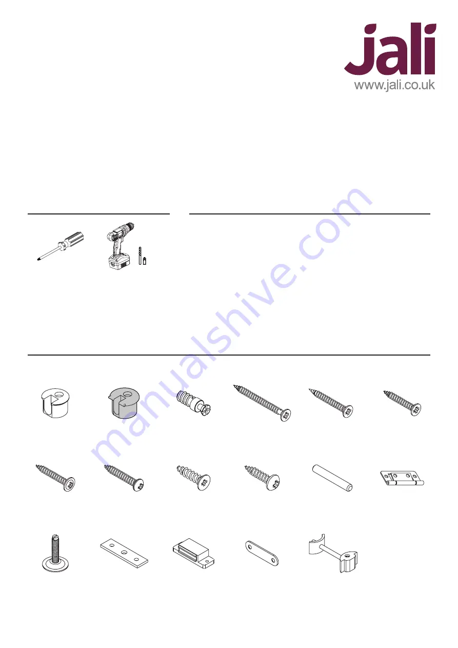
5mm Pozi 

Screwdriver

Power Drill +

2mm Drill Bit

& Pozi Drive

Dresser

Assembly Instructions

YOU WILL NEED

EXTRA

•  Take great care handling and lifting parcels
•  Open parcels with care to avoid damage
•  Check the label to see the contents of each parcel
•  If you have ordered several items, keep it simple: only unpack one item at a time
•  Use the the Parts Diagram sheet to identify and distinguish between parts
•  Any questions: call us on 

01227 833333

, or email 

sales@jali.co.uk

• 

You must fix your product safely in place. Depending 

on your situation, you may choose to use a drill, 
suitable screws and wall plugs

• 

You may wish to use Wood Glue to fix skirting in place

• 

To ensure a perfect fit with your room skirting board, 

you may use a saw to scribe the relevant parts during 
assembly

FIXINGS INCLUDED

White Cam

Nickel Cam

Cam Bolt

25mm WSH 

Screw

Adjustable 

Foot

45mm CSK 

Screw

30mm CSK 

Screw

16mm RND 

Screw

Dowel

Connector

in some cases

20mm RND 

Screw

Magnetic 

Catch

Foot Plate

16mm CSK 

Screw

Magnetic 

Catch Plate

25mm CSK

Screw

Hinge

Plus Door Handles with Bolts as required

Summary of Contents for Dresser

Page 1: ...ons call us on 01227 833333 or email sales jali co uk You must fix your product safely in place Depending on your situation you may choose to use a drill suitable screws and wall plugs You may wish to...

Page 2: ...slight angle and rotate CW to lock the Cam HOW DO CAM BOLTS WORK 1 Start by identifying the parts Your design may be different to this example but don t worry it will become clearer as we work throug...

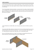
Page 3: ...Side The Cam Bolts in the Base Shelf should face the bottom of the Side so they ll be hidden when the unit is standing upright 2 We ll start with the left hand LH and right hand RH Sides as well as an...

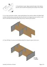
Page 4: ...ide of the Divider If your design has more sections you will have more Dividers and Shelves Keep going until you ve done all the sections 6 Fit the RH Side to the other end of the Base Shelf Don t for...

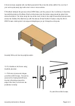
Page 5: ...with the Sides Dividers easily 8 Beneath any Dividers Base Shelf Supports must be attached Fit Cam Bolts in the required 5mm holes on the underside of the Base Shelf Place White Cams in the Base Shel...

Page 6: ...9mm above the bottom The holes along the top will be much closer to the edge Ensure that that any holes across the middle of the Back line up with the shelves Screw the Back in place using the 25mm W...

Page 7: ...placing the LH RH Skirts ensure that the mitre matches neatly with the Front Skirt They can be either glued in place or screwed from the inside using 30mm CSK Screws Now the lower section is complete...

Page 8: ...H Sides and White Cams in the Mid Sides Place White Cams in the Box Top The Box Top can be placed between the two Sides with its two 6mm holes facing the front of the finished section towards the floo...

Page 9: ...to screw the other side or both sides of the Back Strut into the back of the unit Back Strut 18 Lift each section in turn onto the lower assembly Countertop and fix it in place with the Cam Bolts 19...

Reviews: