
IS295-21C
J&D Manufacturing • 6200 Hwy 12 • Eau Claire, WI 54701 • 1-800-998-2398 • www.jdmfg.com
Page 1/13
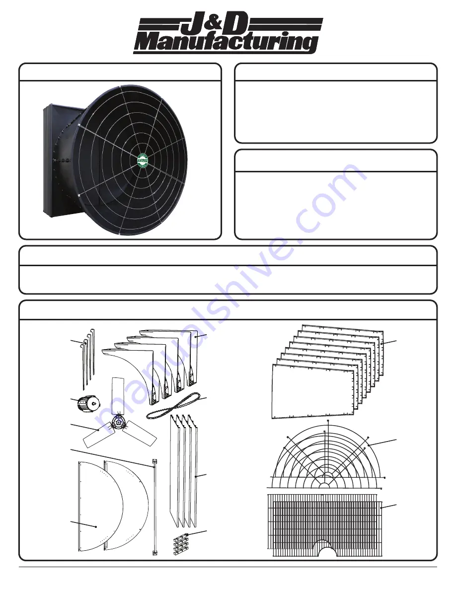
MAGNUM 58” EXHAUST FAN
J&D Mfg. warrants this products is free from defects in materials and workmanship under
normal use for the period of three years from date of purchase. Our warranty does not cover
ordinary wear and tear. J&D Mfg can repair or replace at our option, any product or part of
the product that is found to be defective. Our warranty applies to materials only and does not
include return freight, delivery, loss or damage to personal property, cost of removal or
installation, any incidental or consequential damages or labor. This warranty does not apply to
products which are misused, abused, altered, improperly installed or subject to negligence. All
warranties must be approved through our warranty department. The original purchaser must
present a copy of the invoice for the defective product.
Please read over ALL instructions carefully before you begin.
If you have any questions please call your local dealer, or contact J&D Manufacturing at 1-800-998-2398.
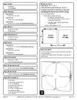
RECOMMENDED TOOLS & SUPPLIES FOR INSTALLATION
AND ASSEMBLY (NOT PROVIDED)
WARRANTY
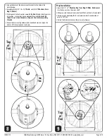
INSTALLATION
(4) Venturi
Sections
Rubber
Gasket
(4) Motor
Brackets
Motor
Prop
Damper Door
Mounting
Bracket
Housing
Side Panels
(2) Damper
Doors
(4) Housing
Corner Caps
(8) Cone
Sections
(2) Front
Guards
(2) Rear
Guards
PARTS LEGEND
Back
Front
• Safety Glasses
• Socket Wrench
• 1/2” Socket
• 1/4” Nut Driver
• Impact Driver
• 1/2” Wrench
• 3/8” Wrench
• Drill
• 1/8” Drill Bit
• 13/64” Drill Bit
• 10 ft-lbs Torque Wrench
• 23 ft-lbs Torque Wrench
• Cutting Device
(for Rubber Gasket)
• Sealant (Minimal-Expanding
Foam / Polyurethane Caulk)


