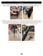
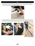
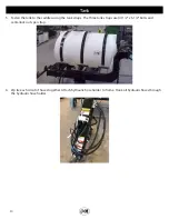
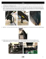
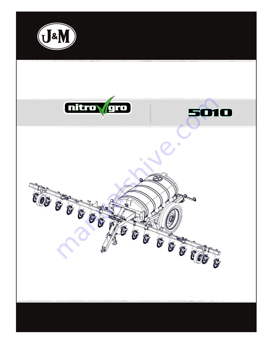
background image

J&M Manufacturing Co, Inc

284 Railroad Street - P.O. Box 547  |  Fort Recovery, OH 45846  |  Ph: (419) 375-2376  |  Fax: (419) 375-2708

www.jm-inc.com

Rev

. 10.2.2019

A S S E M B L Y   M A N U A L

MODEL

Manual

Summary of Contents for Nitro Gro 5010

Page 1: ...J M Manufacturing Co Inc 284 Railroad Street P O Box 547 Fort Recovery OH 45846 Ph 419 375 2376 Fax 419 375 2708 www jm inc com Rev 10 2 2019 A S S E M B L Y M A N U A L MODEL Manual...

Page 2: ...2 1 2 3 4 5 7 9 10 11 12 13 14 15 16 17 18 19 20 2 1 8 7 21 22 23 24 25 26 27 2 6 Decals...

Page 3: ...lve JM0039478 13 Close Tank Fill Valve JM0035891 14 Open Agitation Valve JM0039479 15 Check Filter Daily JM0035884 16 Ground Drive Adjustment JM0038102 17 Ground Drive Tire Pressure JM0038101 18 2 0 x...

Page 4: ...tape measure to ensure the back corner of the applicator frame is approximately 30 off the ground 4 Mount tongue to main frame with 16 3 4 10 x 2 1 2 Gr5 Z Hex Bolt and 16 3 4 10 Gr2 Z Centerlock Hex...

Page 5: ...to the bottom two fittings on the front of the valve bank and extend to the tractor 8 Mount the tank saddles On the rear of the saddles there are two sets of holes One set of holes has two holes and...

Page 6: ...nside of the applicator and yellow lights are located closer to the outside 11 Guide the rear light harness through the conduit on the inside of the rear applicator frame Guide the end of wire harness...

Page 7: ...sure gauge to down pressure relief valve bank 14 Run the 1 2 x 300 and 3 8 x 300 hoses from the front of the tongue along the frame of the applicator all the way to the hydraulic pump on the right pas...

Page 8: ...screw on from the outside These are lefthanded threads 3 4 bulkhead fittings 2 Connect the yellow hose from the valve bank on top of the frame to the down pressure relief valve bank on the middle of...

Page 9: ...rhead hoist The lid should be positioned to the back of the applicator 4 Measure the back of the tank from the frame to the seam at the center of the tank Center the tank so the distance measures abou...

Page 10: ...ing the tank straps The three tank straps use 4 1 2 x 5 1 2 bolts and centerlock nuts per strap 6 Zip tie each circut of hoses together Attach hydraulic hose holder to frame Hook all hydraulic hoses t...

Page 11: ...ecure the jack to the mounting bracket with 5 8 x 2 Gr8 hex bolts and 5 8 centerlock hex nuts Tighten the bolts and keep the jack in place using the 3 4 L pin for mounting plate centerlock pin for top...

Page 12: ...ed in yellow The 1 2 hose should go in check vavle with an arrow pointing out from the pump 12 Attach 1 1 2 pressure hose and tighten clamp use lubricant to slip hose on fitting Pull hose tight throug...

Page 13: ...nd tighten clamp Connect wire harness that comes with Raven control 16 Connect tank shut off valve to the fitting at the bottom of the tank and tighten clamp Ensure that the O ring is centered when co...

Page 14: ...he cap of the valve Before fastening the bolts with the nuts loop one eyelet of the wires over the inside of the bolt and slide a washer in behind it as shown below Thread both nuts onto the bolts and...

Page 15: ...15 Handwash Tank 20 Attach water tank Use plastic thread dope for spout attachment and plugs 21 Attach hose from top front of tank to banjo relief valve on Raven control and tighten clamp...

Page 16: ...ylinders When mounting the cylinders ensure the bolt on the ram side of the cylinder is facing up and the hydraulic fittings face towards the rear of the toolbar Two sizes of pins hold these cylinders...

Page 17: ...e you have the correct one 6 Insert the 2 1 2 diameter pivot pins Set the bolt mounted D ring over the pivot pin so that it covers the retainer and the hole on the D ring lines up with the hole on the...

Page 18: ...18 This page intentionally left blank...

Page 19: ...ese instructions can be used for both the initial setup of your applicator and instructions to change the row spacing on your applicator To change your row spacing loosen the coulters and follow the d...

Page 20: ...ings onto the U bolts behind the channel bracket plate Thread 4 5 8 serrated flange nuts onto the U bolts but leave the nuts loose 5 Slide the coulter rod roll pin and QJ mounting pad down between the...

Page 21: ...ed in areas or hinges that dont allow a direct mount Mount coulter 5 to the front of the wing with an offset mount shown in red below Coulter 5 is the only coulter on the wings that is mounted on the...

Page 22: ...e channel bracket plate Thread 4 5 8 serrated flange nuts onto the U bolts but leave the nuts loose 5 Slide the coulter rod roll pin and QJ mounting pad down between the plate and the casting 6 Make s...

Page 23: ...annel bracket castings directly to the weldment Secure using 5 8 centerlock hex nuts 9 Offset coulter mounts are used in areas or hinges that dont allow a direct mount Coulter 6 and coulter 9 both use...

Page 24: ...he U bolts behind the channel bracket plate Thread 4 5 8 serrated flange nuts onto the U bolts but leave the nuts loose 5 Slide the coulter rod roll pin and QJ mounting pad down between the plate and...

Page 25: ...hinges that dont allow a direct mount Coulter 7 uses an offset coulter mount Offset coulter mounts use 2 5 8 11 x 7 1 8 x 8 11 16 square U bolts with 2 5 8 serrated flange hex nuts Use 4 5 8 x 3 1 2...

Page 26: ...pin and secure with 3 4 x 2 1 2 bolt and 3 4 centerlock hex nut Insert bolt from the inside out so that the nut is on the outside 3 Leave chains attached so it is easier to mount the wheels 4 Mount t...

Page 27: ...e valve bank on the main frame to the 4 x 8 hydraulic lift cylinders These hoses will be labeled in yellow 7 Connect the hoses from the bottom two ports of the valve bank on the main frame to the 4 x...

Page 28: ...rod 2 Mount coulter wheels using 1 2 13 x 2 studs 1 2 lock washer 1 2 13 hex nut and dust cap keeper 3 After mounting the coulters install the knife mounts onto the coulter arm Secure each knife moun...

Page 29: ...bolt is used towards the bottom of the knife and is secured using the hex nut Ensure to mount the knife in line with the coulter Use a shim to adjust the knife out to keep it aligned with the coulter...

Page 30: ...slide in the spindle Take care not to mar the threads on the spindle when lifting After lining up the hole in the spindle with the hole in the axle insert the 1 8 x 7 bolt and secure with 1 nylon lock...

Page 31: ...31 Start adding 3 4 tee and single diaphragm check valves to each QJ mounting pad on each coulter Diaphragm and Fertilizer Hose Placement...

Page 32: ...45 50 or 70cm length hose to connect each coulter based upon which row spacing you are using The blue hose will be the start of boom 2 and the yellow hose will be the start of boom 3 Diaphragm and Fer...

Page 33: ...33...

Reviews: