
FOR YOUR SAFETY - This product must be installed and serviced by authorized person-
nel, qualified in pool/spa heater installation. Improper installation and/or operation can
create carbon monoxide gas and flue gases which can cause serious injury, property
damage, or death. Improper installation and/or operation will void the warranty.
H0214000B
Installation and Operating Data
WARNING
If these instructions are not followed exactly, a fire or explosion may result,
causing property damage, personal injury, or death.
Do not store or use gasoline or other flammable vapors and liquids in the
vicinity of this or any other appliance.
WHAT TO DO IF YOU SMELL GAS
• Do not try to light any appliance.
• Do not touch any electrical switch; do not use any phone in your building.
• Immediately call your gas supplier from a neighbor’s phone. Follow the gas
supplier’s instructions.
• If you cannot reach your gas supplier, call the fire department.
Installation and service must be performed by a qualified installer, service
agency or the gas supplier.
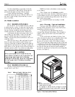
Installation and
Operation Manual
LX
™
and LT
™
Gas-Fired Pool
and Spa Heater
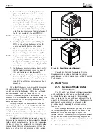
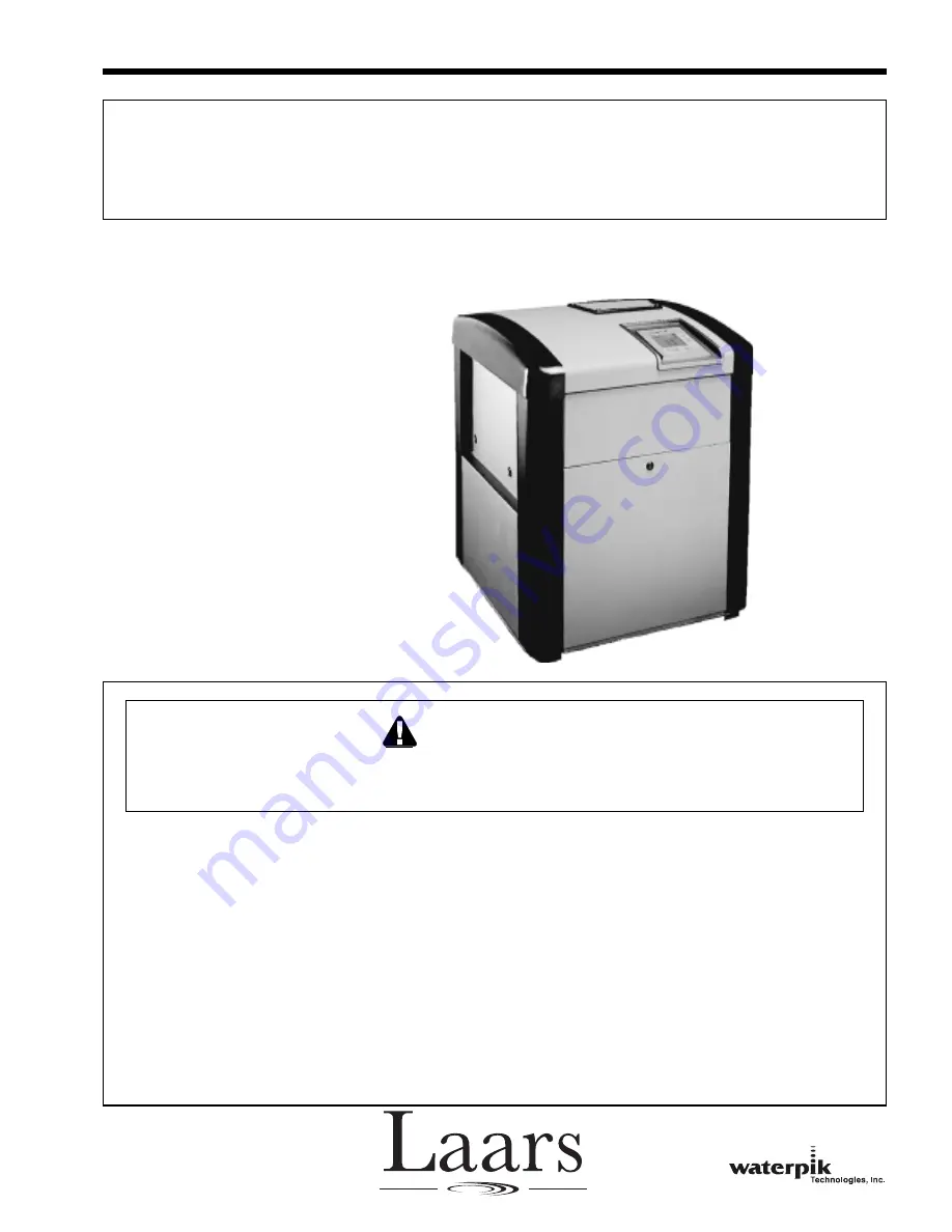
Model
LX250
Shown