background image

H0490000_REVE

 WARNING

FOR YOUR SAFETY - This product must be installed and serviced by a contractor who is licensed and 

qualified in pool equipment by the jurisdiction in which the product will be installed where such state 

or local requirements exist. The maintainer must be a professional with sufficient experience in pool 

equipment installation and maintenance so that all of the instructions in this manual can be followed 

exactly. Before installing this product, read and follow all warning notices and instructions that accompany 

this product. Failure to follow warning notices and instructions may result in property damage, personal 

injury, or death. Improper installation and/or operation will void the warranty.
Improper installation and/or operation can create unwanted electrical hazard which can cause serious 

injury, property damage, or death. 

ATTENTION INSTALLER - This manual contains important information about the 

installation, operation and safe use of this product. This information should be given to 

the owner/operator of this equipment.

ENGLISH   

|

   FRANÇAIS   |   ESPAÑOL

Jandy Pro Series

VS PlusHP 

Pumps


Models VSPHP270JEP

& VSPHP270AUT

INSTALLATION AND 

OPERATION MANUAL

Summary of Contents for Pro VSPHP270JEP

Page 1: ...l warning notices and instructions that accompany this product Failure to follow warning notices and instructions may result in property damage personal injury or death Improper installation and or operation will void the warranty Improper installation and or operation can create unwanted electrical hazard which can cause serious injury property damage or death ATTENTION INSTALLER This manual cont...

Page 2: ...on 2 General Description 6 2 1 Introduction 6 2 2 Description 6 2 3 Preparation 6 Section 3 Installation 6 3 1 Plumbing 6 3 2 Electrical Installation 8 Section 4 Operation 12 4 1 Remove Pump Lid 12 4 2 Conduct Pressure Test 13 4 3 Start up 13 TABLE OF CONTENTS Section 5 Maintenance 14 5 1 Routine Maintenance 14 5 2 Winterizing the Pump 14 Section 6 Troubleshooting and Repair 15 Section 7 Product S...

Page 3: ...ushed a ground current is flowing indicating the possibility of electrical shock Do not use the pump Disconnect the pump and have the problem corrected by a qualified service representative before using Due to the potential risk of fire electric shock or injuries to persons Zodiac Pumps must be installed in accordance with the National Electrical Code NEC all local electrical and safety codes and ...

Page 4: ...E FOLLOWING SAFETY INSTRUCTIONS Check all clamps bolts lids lock rings and system accessories to ensure they are properly installed and secured before testing RELEASE ALL AIR in the system before testing Water pressure for test must NOT EXCEED 35 PSI Water temperature for test must NOT EXCEED 100 F 38 C Limit test to 24 hours After test visually check system to be sure it is ready for operation NO...

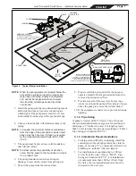
Page 5: ...h drain See Figure 1 More than one 1 pump can be connected to a single suction line as long as the requirements above are met Water Velocity The maximum water velocity through the suction outlet assembly and its cover for any suction outlet must not exceed the suction fitting assembly and it s cover s maximum design flow rate The suction outlet drain assembly and its cover must comply with the lat...

Page 6: ...02 03 04 05 06 07 08 09 10 11 12 13 14 15 VSPHP27 Pump Installation and Operation Manual Large Drawstring Bag Universal Union Nut Tailpiece O Ring Small Drawstring Bag User Interface Universal Control Backplate Universal Control DIP Switch Label Cable Label 4 Conductor Cable Terminal Bar 4 Pin Manilla Envelope Mounting Screw 1 1 1 2 2 2 1 1 1 1 1 1 1 1 6 ITEM DESCRIPTION QTY For VSPHP27JEP Models ...

Page 7: ...VE Check Valve recommended for systems installed with Erosion Feeders or Aquapure salt chlorination systems PUMP POOL SPA 3 WAY VALVE SPA DRAIN Suction Outlet SKIMMER SPA RETURN POOL RETURN a a MANUAL BY PASS DETAIL USE WHEN FILTRATION RATE EXCEEDS 125 GPM FOR ZODIAC HEATERS REFER TO THE MANUFAC TURER S RECOMMENDATIONS IF USING A DIFFERENT BRAND HEATER 8 Proper ventilation is required for the pump...

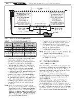
Page 8: ...e latest published version of ANSI ASME A112 19 8 or its successor standard ANSI APSP 16 Anti entrapment Cover Grate or Suction Fitting securely fastened to Main Drain Sump Listed certified to the latest published version of ANSI ASME A112 19 8 or its successor standard ANSI APSP 16 Anti entrapment Cover Grate or Suction Fitting securely fastened to Main Drain Sump At Least 3 Feet Suction Outlet M...

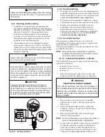
Page 9: ...ng to connect to an electrical power supply Do not ground to a gas supply line 2 Wire size must be adequate to minimize a voltage drop during the start up and operation of the pump 3 Insulate all connections carefully to prevent grounding or short circuits Sharp edges on terminals require extra protection For safety and to prevent entry of contaminants reinstall all conduit and terminal box covers...

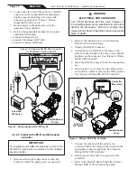
Page 10: ...ct the high voltage lines or open any breaker to which the pump power is connected WARNING ELECTRICAL SHOCK HAZARD Turn off all switches and the main breaker in the variable speed pump electrical circuit before starting the procedure Failure to comply may cause a shock hazard resulting in severe personal injury or death 2 Remove the junction box cover and feed the RS 485 cable into the fitting 3 U...

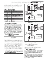
Page 11: ...ay be ordered from the National Protection Association 470 Atlantic Ave Boston MA 02210 or from your local government inspection agency In Canada Zodiac Pumps must be installed in accordance with the Canadian Electrical Code CEC THE Auxiliary Load relay contacts are rated at 230V 11A RMS Please ensure the requirements of the equipment to be connected to the Auxiliary Load do not exceed this rating...

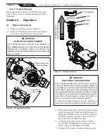
Page 12: ...Figure 10 Remove Pump Lid WARNING ELECTRICAL SHOCK HAZARD Due to the potential risk of fire electric shock or injuries to persons Zodiac Pumps and any auxiliary loads must be installed in accordance with the National Electrical Code NEC all local electrical and safety codes and the occupational Safety and HealthAct OSHA Copies of the NEC may be ordered from the National Protection Association 470 ...

Page 13: ...rly pressure tested Check the filter for proper installation verifying that all connections and clamps are secure according to the manufacturer s recommendations CAUTION Never run the pump without water Running the pump dry for any length of time can cause severe damage to both the pump and motor and will void the warranty 1 Release all pressure from the system and open the filter pressure release...

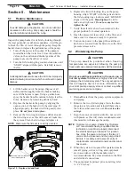
Page 14: ...cking ring clockwise until LOCKED aligns with the ports Hand tighten the lid to make an air tight seal Do not use any tools to tighten the lid 7 Verify that all valves have been returned to the proper position for normal operation 8 Open the pressure release valve on the filter and make sure it is clean and ready for operation 9 Turn on the power to the pump Once all the air has been evacuated fro...

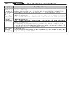
Page 15: ...e unions still do not seal gently tighten with a large pair of tongue and groove pliers Do not over tighten There is no air in the system but the pressure is still low It is possible that debris is caught in the pump impeller The pump impeller moves the water and the vanes in the impeller can become blocked with debris There is no debris blocking the impeller and the pressure is still low The pump...

Page 16: ...ecessary See 3 2 Electrical Installation Controller displays Pump not connected Improper low voltage wiring Check low voltage wiring between pump and controller Correct if necessary See 3 2 Electrical Installation Improper pump address set Ensure pump dip switches 3 and 4 are set properly for the installation Both should be OFF for use with Variable Speed Controller or set to the proper address wh...

Page 17: ...arge Speed Drive w Gasket GEN II R0562300 8 Data Cable Feed Thru R0501100 9 Impeller Replacement Kit R0807200 10 Diffuser w O ring Hardware R0445400 11 Mechanical Seal Carbon and Ceramic R0479400 12 Pump Body R0448700 Key No Description Order Part No 13 Motor Mounting Foot Assembly w Screws R0445700 14 Locking Ring w Lid Seal R0448800 15 Pump Debris Filter Basket R0448900 16 Drain Plug w O ring R0...

Page 18: ...Series Pump Performance Curves 3450 RPM 2750 RPM 1730 RPM 1000 RPM CURVE A CURVE C CURVE B 7 4 Physical and Operational Specifications 7 4 1 Pump Specifications Model No HP Voltage Max Watts Pipe Size Carton Weight Overall Length A VSPHP270 0 25 2 7 230 VAC 2 250W 2 3 50 lbs 30 3 8 7 4 3 PHP Pump Dimensions 9 1 8 232 mm 8 7 8 226 mm 9 229 mm 31 788 mm 11 3 8 289 mm 13 7 8 353 mm 14 1 8 378 mm Bolt...

Page 19: ...Page 19 ENGLISH Jandy Pro Series VS PlusHP Pumps Installation Operation Manual NOTES ...

Page 20: ...m 2017 Zodiac Pool Systems LLC ZODIAC is a registered trademark of Zodiac International S A S U used under license All trademarks referenced herein are the property of their respective owners H0490000 REVE Certified to NSF ANSI Standard 50 CONFORMS TO UL STD 1081 CERTIFIED TO CSA STD C22 2 NO 108 ...

Reviews: