background image

SERVICING MANUAL

Model 659

Summary of Contents for 659

Page 1: ...SERVICING MANUAL Model 659...

Page 2: ...eedle swing 10 Distribution of needle swing 11 Needle clearance to hook 12 Backlash lower shaft gear 13 Needle bar height 14 Needle to hook timing 15 Feed dog height 16 Button hole stitch balance 17 S...

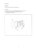
Page 3: ...VE 1 Remove the 2 set screws and the face cover TO ATTACH 2 Replace the face cover B by lightly tightening the 2 set screws A 3 Close the face cover B carefully aligning it with the arm Then tighten t...

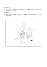
Page 4: ...T COVER TO REMOVE 1 Loosen the set screw A and remove the belt cover rib B by pulling out the belt cover C rib from the front cover D TO ATTACH 2 Mount the belt cover rib B to the front cover D then...

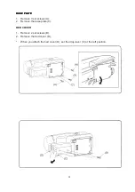
Page 5: ...PLA BASE PLA BASE PLATE TE TE TE TE 1 Remove 3 set screws A 2 Remove the base plate C BED COVER 1 Remove 2 set screws B 2 Remove the bed cover D When you attach the bed cover D set the drop lever C a...

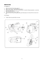
Page 6: ...ove the selector dial M and dial plate L 3 Remove the cap N then set screws A B C and Arm thread guide K Loosen the set screws D and E 4 Remove the notches H I and J 5 Push and lower the part F gently...

Page 7: ...and F 4 While pushing up the rear cover O near the notches L M and N pull upper part of the rear cover See Y below 5 Pull lower part of the rear cover toward you and slide it to the left See X below...

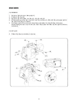
Page 8: ...ARM COVER ARM COVER ARM COVER ARM COVER TO REMOVE 1 Remove the set screw A and the needle plate C 2 Remove the bed cover See page 4 3 Remove the set screw B and the free arm cover D TO ATTACH 4 Follo...

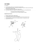
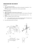
Page 9: ...the thread A up 4 Top tension should be 75 90g when pulling the thread A up in the direction B Use white polyester sewing thread size 50 If the tension is out of the range adjust as follows Adjustmen...

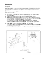
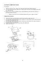
Page 10: ...mm 0 24 adjust as follows Adjustment procedure 1 Open the face cover 2 Remove the set screw G and remove the lamp socket 3 Raise the presser foot lever B and loosen the hexagon socket screw D on the...

Page 11: ...haft worm gear B 3 While holding the upper shaft worm gear in place carefully turn the hand wheel and adjust so that lateral needle swing starts from a position 2 to 3mm C above the needle plate after...

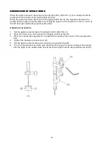
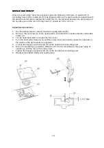
Page 12: ...uld be equal and it should be 0 2 mm or more at the left and right needle drop positions B and C Adjustment procedure 1 Set the pattern selector dial at the straight stitch stitch No 2 2 Open the face...

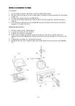
Page 13: ...nd until the needle bar reaches its lowest position 5 The clearance between the test pin 68368 D and the point of the hook E should be between 0 10 and 0 05 mm Adjustment procedure 1 Remove the bed co...

Page 14: ...within 0 8 mm K If there is more than 0 8 mm backlash between the gears adjust as follows Adjustment procedure 1 Remove the bed cover See page 4 and loosen hexagon socket screw F 2 Turn the lower shaf...

Page 15: ...Set the pattern selector dial at maximum zigzag stitch width 2 Remove the set screw A of the needle plate and detach the needle plate B and bobbin holder C 3 Tilt the head backward and open the face...

Page 16: ...No 6 2 Remove set screw A on the needle plate to remove the needle plate B and bobbin holder C 3 Remove the bed cover See page 4 4 Loosen hexagon screws D on the lower shaft gear E 5 Turn the hand whe...

Page 17: ...length dial at 4 and lower the presser foot H 2 Turn the hand wheel until the feed dog G comes to its highest position 3 Remove the bed cover See page 4 4 Loosen set screw A and nut B 5 Turn the adju...

Page 18: ...ed with 10 stitches on the right row ADJUSTMENT PROCEDURE 1 Attach buttonhole foot R and sew a buttonhole Check the stitch density on the right and left rows 2 Remove the cap G 3 Loosen the hexagon so...

Page 19: ...e figure below If not balanced make an adjustment as follows Adjustment procedure 1 Remove the cap F 2 If the reverse stitch length B is shorter than the forward stitch length A turn the adjusting set...

Page 20: ...ou 4 The machine should not feed a piece of paper with the above setting Adjustment procedure 1 Remove the belt cover See page 3 2 Set the pattern selector dial at straight stitch stitch No 2 and the...

Page 21: ...e cover 3 Loosen set screw A 4 Pull down the buttonhole lever E until it touches buttonhole foot R The lever B should touch the front base plate F Also make sure buttonhole lever adjusting plate C tou...

Page 22: ...n too early or if no bar tack is sewn at all adjust as follows Adjustment procedure 1 Remove the belt cover See page 3 2 Turn the hexagon socket screw A in the direction of C if bar tack is sewn too s...

Page 23: ...belt tension is too loose it may cause the belt teeth on the motor pulley to jump 2 The correct motor belt tension is achieved when the belt pushes in about 7mm 9mm under a pressure of about 300 grams...

Page 24: ...in X TO CHANGE THE NEEDLE THREADER 1 If the hook D of the threader plate C touches the left or right side of the needle eye loosen the set screw B and adjust the hook position as shown in Y 2 If the h...

Page 25: ...WIRING OF TERMINAL BLOCK L from lamp socket M from motor 24...

Reviews: