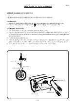
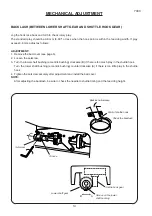
background image

Servicing Manual

Model 7330

Summary of Contents for 7330 MAGNOLIA

Page 1: ...Servicing Manual Model 7330...

Page 2: ...SYNCHRONIZATION 16 NEEDLE THREAD TENSION 17 STRETCH STITCH FEED BALANCE 18 REPLACEMENT AND ADJUSTMENT OF THE NEEDLE THREADER PLATE 19 CONNECTOR DIAGRAM 20 SELF DIAGNOSTIC TESTS 21 SELF DIAGNOSTIC SHEE...

Page 3: ...a 11 blue tip needle Adjust the presser bar level to make the pressure stronger See mechanical adjustment Needle bar height See mechanical adjustment Needle to shuttle timing See mechanical adjustmen...

Page 4: ...readed bobbin 2 Too much thread is around on the bobbin 3 Lint is stuck inside the bobbin holder 4 Thread quality is too low 5 Thread is jamming around the bobbin Thread bobbin correctly Adjust the po...

Page 5: ...acklash lower shaft gear Eliminate the looseness See part removal and replacement driving motor DC motor Oil all moving parts p 14 p 28 p 36 7 Deformation pattern 1 Inappropriate feed balance 2 Inappr...

Page 6: ...e the face cover TO INSTALL 3 Insert the 2 ribs of the face cover into the rear cover and tighten the setscrew then attach the cap TOP COVER TO REMOVE 1 Remove the face cover 2 Remove the setscrew B C...

Page 7: ...een the base and the arm leg Install the base with the 4 setscrews A and the 2 setscrews BED COVER TO REMOVE 1 Set the drop lever to the left and remove the 2 setscrews C remove the bed cover TO INSTA...

Page 8: ...6 7330 SERVICE ACCESS 3 BELT COVER TO REMOVE 1 Remove the setscrew A B and remove the belt cover TO INSTALL 2 Install the belt cover with the setscrew A and B Setscrew A Setscrew B Belt cover...

Page 9: ...ll on the lead wire as this may damage the contact sleeve inside the connector TO INSTALL 4 To install the front cover follow the above procedure in reverse NOTES TO CONNECT THE CONNECTORS 1 Be sure t...

Page 10: ...Loosen the setscrews A B C and D then remove the setscrew E To remove the cover detach the presser foot lifter section first with the presser foot lifter in the down position TO INSTALL 3 Follow the...

Page 11: ...eed dog window on the needle plate should be parallel 1 Remove the face cover and raise the presser foot Loosen the setscrew to adjust the presser foot height 6 0 mm and the presser foot alignment 2 T...

Page 12: ...maximum then check the needle drop position 2 If the needle drop position is not in the center of the needle plate hole when the straight stitch is selected or if the clearance between the needle and...

Page 13: ...hestraight stitch pattern no 2 left needle position 3 Remove the bed cover 4 Turn the handwheel toward you and set the needle bar at the lowest position 5 Loosen the setscrews on the lower shaft timin...

Page 14: ...ascending travel of needle from its left and lowest poosition 1 Remove the needle plate and bobbin holder 2 Turn on the power switch 3 Select the pattern simple zigzag Maximum zigzag width 4 Turn the...

Page 15: ...he clearance between master needle and the point of the hook in the left and right needle position to 0 1 to 0 05 mm by moving the hook in the left and right by moving the hook set plate up or down 3...

Page 16: ...Turn the lower shaft bushing eccentric bushing clockwise B if there is too much play in the shuttle hook Turn the lower shaft bushing eccentric bushing counterclockwise A if there is too little play i...

Page 17: ...he pressure dial at 3 and lower the presser foot 2 Turn on the power switch 3 Remove the bed cover 4 Turn the handwheel toward you to set the feed dog at the highest position 5 Loosen the setscrew A a...

Page 18: ...toward you slowly with your hand until the needle start to sewing Loosen the setscrew and turn the upper shaft shield plate in the direction of A If the swing point is higher than 7 5 mm B If the swi...

Page 19: ...lled at aproximately 110 mm sec If the tension is outside the standard range adjust as follows ADJUSTMENT 1 Set the thread tension dial to 4 and check the thread tension 2 Remove the front cover see p...

Page 20: ...r switch on and select the stitch pattern 2 Set the slit of the feed balancing dial to the standard setting mark on the front cover 3 Put a piece of paper under the presser foot and lower it Turning t...

Page 21: ...TO REMOVE 1 Push down the needle threader knob and pull the needle threader plate A down to remove it see FIG 1 2 To install the needle threader plate line the groove up with the pin B and push it up...

Page 22: ...toward the printed circuit board to unlock them NOTE TO CONNECT THE CONNECTORS 1 Be sure that the color of each connector corresponds to the color of the connector post on the printed circuit board P...

Page 23: ...ted PRELIMINARY TEST Turn on the power switch If any of following problems occur take the recmmended actions in the order they are shown The machine does not respond when the power switch is turned on...

Page 24: ...rse button within 2 5 seconds the machine automatically reverts to normal sewing mode Press needle up down button led displays 02 for one second Press needle up down button led displays 03 for one sec...

Page 25: ...ise and lower the needle to its highest and lowest position When the needle is at the highest position led displays LH When the needle is at the lowest position led displays LH When the needle is half...

Page 26: ...the left to the right then return it to the left CORECT CONDITION When the speed control lever is at the left led displays 00 The indicated value hexadecimal increases as you move thew speed control l...

Page 27: ...inished turn off the power switch Press needle up down button led indicates 12 for one swcond Press foot control Led indicates dc Machine runs at the speed set by the speed control lever Full left 80...

Page 28: ...machine socket and power transformer connectors pull them while pushing them toward the a board to unlock them TO INSTALL 4 To install follow the above procedure in reverse NOTE When installing board...

Page 29: ...e volume moves smoothly back and forth REPLACING PRINTED CIRCUIT BOARD F TO REMOVE 5 Remove the front cover unit 6 Unplug the printed circuit board F connector and remove the three cs rings B 7 Remove...

Page 30: ...page 7 and 8 2 Remove the two setscrews then remove the DC motor and belt TO INSTALL 3 Lightly tighten the two screws 4 Put the motor belt on the pulley and adjust the belt deflection to about 7 to 9...

Page 31: ...setscrews and lift off the cover on printed circuit board A 3 Remove the fuse Pry it out with a screwdriver TO INSTALL 4 Follow the above procedure in reverse NOTE 1 Replace the printed circuit board...

Page 32: ...and rear cover see page 7 and 8 2 Remove the two screws and remove the machine socket TO INSTALL 3 To install the machine socket follow the above procedure in reverse NOTE Pull out the cord in front o...

Page 33: ...3 To install the transformer follow the above procedure in reverse NOTE Place the rear end of the transformer on the transformer support Slide the two transformer wire tubes to the side of transforme...

Page 34: ...g width motor follow the above procedure in reverse NOTE 1 The setscrew of zigzag rod should be tightened to 5 7 kg of torque 2 Check to ensure that the upper shaft sensor mounted on the zigzag width...

Page 35: ...ing E 3 3 Remove the two setscrews and remove the feed motor TO INSTALL 4 To install the feed motor follow the above procedure in reverse NOTE Adjust the stretch stitch patterns see page 21 REPLACING...

Page 36: ...led display changes from l to H 7 Next turn the adjusting screw to the right until the led display changes from H to l 8 Check the led When the clearance of the buttonhole foot is 1 4 mm the led disp...

Page 37: ...er arm and the switch fixing plate to o 7 to 1 3 mm 3 Tighten the setscrew 4 Install the front cover TO CONFIRM Turn the power switch on The led displays when the bobbin winder spindle is set the bobb...

Page 38: ...d still check for possible lubrication needs whenever servicing machines OIL Use good quality sewing machine oil at the points A B C D E F G H I J K indicated by the black arrows GREASE Use white grea...

Reviews: