background image

SERVICE MANUAL

&

PARTS LIST

MODEL: MB-7e (V2)

First Edition: 02 October 2020

Summary of Contents for MB-7e

Page 1: ...SERVICE MANUAL PARTS LIST MODEL MB 7e V2 First Edition 02 October 2020 ...

Page 2: ......

Page 3: ...10 Replacing the Needle Needle and Thread Reference Table 11 Adjusting the Bobbin Thread Tension 12 Checking the Lowest Position of the Needle 13 Replacing the Needle Bar Rest 14 Replacing the Take up Lever Cam Roller 15 Adjusting the Take up Lever Timing 16 Replacing the Presser Foot Cam 17 to 19 Replacing and Adjusting the Presser Foot 1 20 Replacing and Adjusting the Presser Foot 2 21 Replacing...

Page 4: ...tion Stopper Plate 34 Replacing the Thread Take up Lever 35 Adjusting the Check Spring Tension 36 Adjusting the Check Spring Stroke 37 Adjusting the Thread Catcher Holder 38 Replacing the Thread Catcher Loop Tape 39 Replacing the Lateral Moving Unit 40 Adjust the Hook Timing 41 Adjusting the Position of the Hook Stopper 42 Replacing the Thread Cutter Driving Roller 43 Replacing the Dynamic Cutter ...

Page 5: ...Timing Belt Tension 54 Replacing the Timing Belt 55 Adjusting the Motor Belt Tension 56 Replacing the Motor Belt 57 Replacing the DC Motor 58 To Reset Motor Drive Time 59 Adjusting the Needle Upper Shaft Timing 60 Adjusting the Moving Head Stop Position 61 Adjusting the Needle Stop Position 62 Adjusting the Carriage Home Position 63 Securing the Cables in the Moving Head Upper Part 64 Instructions...

Page 6: ...Remove the setscrews 3 pcs and spool stand To attach 2 Attach the spool stand and tighten the setscrews 3 pcs Setscrew Replacing the Spool Stand To remove 1 Remove the setscrews 2pcs and thread tension panel To attach 2 Attach the thread tension panel and tighten the set screws 2 pcs Setscrew ...

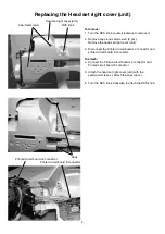
Page 7: ...d K connector To attach 4 Connect the Printed circuit board L2 connector and Printed circuit board K connector 5 Attach the head set right cover unit with the setscrews A 2pcs Attach the caps 2pcs 6 Turn the RCS knob clockwise to attach the RCS knob Replacing the Head set right cover unit RCS knob Cap Setscrew A Hook Printed circuit board L2 connector Printed circuit board K connector Head set rig...

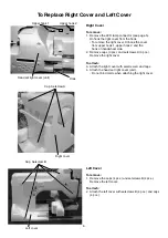
Page 8: ... 2 Remove caps 3 pcs and setscrews A 3 pcs Remove the right cover To attach 3 Attach the right cover with setscrews A and caps 4 Attach the head set right cover unit Do not bind cords when attaching the right cover Left Cover To remove 1 Remove the caps 4 pcs and setscrews B 4 pcs Remove the left cover To attach 2 Attach the left cover with setscrews B 4 pcs and caps 4 pcs Cap Setscrew A Cap Setsc...

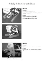
Page 9: ...base cover To attach 3 Attach the machine into the base cover 4 Tighten the setscrews A 6 pcs securely Replacing the Base Cover and Bed Cover Bed Cover To remove 1 Remove the setscrew B and setscrew C Remove the bed cover To attach 2 Attach the bed cover with the setscrew B and setscrew C Setscrew A Setscrew B Setscrew C ...

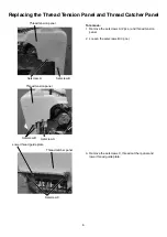
Page 10: ...tscrews A 2 pcs and thread tension panel 2 Loosen the setscrews B 3 pcs 3 Remove the setscrews C thread catcher panel and lower thread guide plate Setscrew A Setscrew A Thread tension panel Thread tension panel Setscrew B Setscrew B Setscrew C Thread catcher panel Lower thread guide plate ...

Page 11: ...burrs or scratches 4 Lower guide plate a There should be no burrs or scratches 5 Needle a Needles should not be bent or blunt To check the needle Touch the tip of the needle and slide it over on your nail and slid it lightly The needle must be blunt if there is any scratch on your nail after sliding the needle on your nail In that case replace the needle Place the flat side of the needle onto some...

Page 12: ...resser foot 8 Hook race a There should be no burrs or scratches b The tip of hook race should not be blunt c There should be no detectable play in the hook and hook race 9 Thread keeper a There should be no burrs or scratches especially on the tip of the thread keeper 10 Check spring a The check spring should not be worn Checking the Thread Paths 2 Hook Thread keeper Upper side Lower side ...

Page 13: ...the needle clamp screw Needle clamp screw Needle Long groove Needle and Thread Reference Table Use DBxK5Q1NY needles and select an appropriate size of needle for threads and fabrics to be sewn An inappropriate size of needle may cause skip stitches thread breakage or loose seam Please refer to the table below and select the suitable needle size 75 8 to10 120 9 to 11 200 11 to 14 Thread Size Denier...

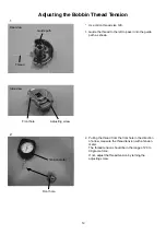
Page 14: ...hole in the direction of arrow measure the thread tension with a tension meter The thread tension should be in the range of 20 to 30 grams force If not adjust the thread tension by turning the adjusting screw 1 2 Adjusting the Bobbin Thread Tension Thread Front hole Tension meter Front hole Adjusting screw Rear view Guide path Side view ...

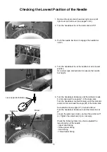
Page 15: ...he handwheel clockwise until the indicator reads 0 2 mm and read the angle Aº of the index disk Turn the handwheel counterclockwise until the indicator reads 0 2 mm and read the angle Bº of the index disk Calculate the mean angle Cº C A B 360 2 Turn the handwheel clockwise to set the index disk at Cº Loosen the setscrews 2 pcs and set the pointer at 0º L Tighten the setscrews 2 pcs securely Check ...

Page 16: ...osen the setscrew C Pull the main shaft up and remove it from the machine 4 Loosen the setscrew D and remove the needle bar rest from the main shaft To attach 5 Reverse the procedure above Attach the needle bar main shaft so its bottom end is level with the bottom surface of the head frame 6 Adjust the needle height after the replacement Setscrew A Thread catcher unit connecter Setscrew B Main sha...

Page 17: ...haft thread take up lever unit and washer 5 Loosen the setscrew Remove the cam roller shaft and cam roller To attach 6 Reverse the procedure above When attaching the thread take up lever shaft tighten the screw while pressing the thread take up lever shaft lightly Drive cover Setscrew Thread take up lever spring Setscrew Thread take up lever shaft Thread take up lever unit Cam roller Cam roller sh...

Page 18: ...t loosen the setscrew on the cam clamp and turn the take up lever cam so the positioning pin can go into the pin groove on the cam Turn the handwheel to set the index disk at 6º Tighten the setscrew on the cam clump while pressing the take up lever cam to the side of the dynamic head There should be no gap between the take up lever cam and cam clamp 5 Pull the positioning pin out from the arm Turn...

Page 19: ...Supporting shaft Presser foot block Presser foot lever unit Setscrew B Snap ring E Poly slider Rulon washer Setscrew B The presser foot cam shall be replaced as the crank unit Rulon washer 1 Remove the spool stand head set right cover right cover left cover moving head thread catcher unit and needle bar rest The lateral moving unit is not needed to remove 2 Remove the setscrews A 2 pcs and the lef...

Page 20: ...setscrews C 2 pcs 6 Remove the setscrew B Pull the crank out to the front to remove it Setscrew C Crank unit Setscrew B 5 Loosen the setscrews C 2pcs 6 Remove the setscrew B Pull the crank out to the front to remove it Replacing the Presser Foot Cam 2 ...

Page 21: ...t the position of the lateral moving unit refer to page 40 of service manual 11 Attach the covers according to the procedures Replacing the Presser Foot Cam 3 7 Apply the grease to the groove of the presser foot cam Recommended grease MOLYKOTE R EM 30L 8 Reverse the procedure to reinstall the parts Do not attach the covers yet 9 Check the lowest position of the needle see page 13 10 Adjust the pos...

Page 22: ...NOTE The presser foot will spring down when the needle clamp is removed 3 Remove the setscrew and replace the presser foot 4 Attach the needle needle clamp and needle clamp cushions Tighten the needle clamp screw and setscrew 5 Adjust the needle height see Adjusting the needle height see page 32 6 Push the needle bar down to engage the needle bar clutch Needle cramp cushion Needle clamp screw Sets...

Page 23: ... 2 7 Turn the handwheel to set the index disk at 0º L 8 Insert the 1 2 mm thick gauge between the needle plate and the presser foot 9 Tighten the setscrew 10 Turn the handwheel to reset the index disk at 270º 11 Attach the removed parts Setscrew ...

Page 24: ... needle bar No 1 Step 2 Removing the Needle Bar 1 Remove the thread tension panel lower thread guide plate and thread catcher panel see page 8 2 Remove the 2 setscrews A and the tension control unit 3 Loosen the needle clamp screw and remove the needle 4 Lower the needle bar Loosen the hexagonal socket screw and remove the needle clamp 5 Remove the setscrew B presser foot and cushion Setscrew A Se...

Page 25: ...ront Tighten the needle clamp screw through the needle clamp and into the lower hole in the needle bar Insert the needle with the long groove facing front in line with the upper hole 11 Tighten the needle clamp screw lightly while pressing the needle clamp down Turn the hand wheel to lower the needle bar at its lowest position Hold the needle clamp with your fingers and tighten the hexagonal socke...

Page 26: ...Insert the 1 2 mm thickness gauge between the presser foot and needle plate Press the presser foot down against the gauge 20 Tighten the setscrew B securely 21 Remove the needle bar height gauge 22 Turn the hand wheel to match the alignment line on it with the joint of the right and left covers the upper shaft will be set at 270 degrees To replace the spring and washer on other needle bars follow ...

Page 27: ...hread catcher connector Remove the setscrews A 2 pcs setscrew B and the thread catcher To attach 3 Connect the thread catcher connector Tighten the setscrews A and setscrew B while pressing the thread catcher unit in the direction of arrows as illustrated 4 Adjust the thread catcher see page 38 5 Attach the removed parts Setscrew A Connector Setscrew B ...

Page 28: ...d catcher guide 3 Remove the thread catcher hook screw Remove the thread catcher hook To attach 4 Attach the thread catcher hook with the thread catcher hook screw 5 Attach the thread catcher guide with the setscrews 6 pcs 6 Attach the thread catcher unit see page 25 Setscrew Thread catcher hook screw Thread catcher hook Thread catcher guide ...

Page 29: ...he slope cam should slide on the slope cam guide smoothly Clean the solenoid if there is any lint or dust on it 4 Attach the jump solenoid to the machine Tighten the setscrews The setscrews should be positioned at the center of holes as shown 5 Attach the head set right cover unit Setscrew Connector Slope cam Slope cam guide Solenoid bracket Jump solenoid ...

Page 30: ...pushing the head in the direction of the arrows If there is a detectable play loosen the setscrew and tighten it while pressing the adjusting roller against the needle drop adjusting rail 3 Adjust the needle drop position see page 31 4 Attach the head set right cover unit Needle drop adjusting rail Adjusting roller Setscrew ...

Page 31: ...the left or right side of stopper screw on the rail shaft 4 Turn the idler gear to move the moving head to the end of the rail shaft with the stopper screw removed Support the moving head securely while removing the moving head so as not to fall To attach 5 Attach the moving head Tighten the stopper screw Setscrew Connector Connector Connector Idler gear Stopper screw Rail shaft Connector Cord cla...

Page 32: ...heck the needle drop position The needle drop position should be the center of the needle hole If the needle drop position is off position to the front or rear adjust the needle drop position see the next page If the needle drop position is off position in the lateral direction adjust the position of the lateral moving head see page 40 10 Turn the handwheel one complete turn to set the index disk ...

Page 33: ...the needle bar No 3 down to engage the needle bar clutch 2 Turn the handwheel until the needle goes down into the needle hole Loosen the setscrews 2 pcs Adjust the needle drop position adjusting plate Center the needle drop position in the needle hole 3 Adjust the hook timing see page 41 Setscrew Needle drop position adjusting plate Needle Needle hole ...

Page 34: ...e needle bar supporter screw 6 Insert the needle bar height gauge into the hook 7 Adjust the needle bar height so the tip of needle slightly touches the gauge 8 Adjust the direction of needle clamp as illustrated below the needle clamp screw is at 5 o clock Tighten the setscrew 9 Remove the needle bar height gauge 10 Turn the handwheel to set the index disk at 270º 11 Attach removed parts Setscrew...

Page 35: ...ar as the desired part can be removed 4 Insert the needle bar down into the frame and put the parts on the needle bar as it goes 5 Attach the presser foot 6 Adjust the needle height see page 32 7 Adjust the presser bar height see pages 20 and 21 Needle bar Needle bar spring Needle bar holder Spring base Presser foot spring lower Presser foot block Stop felt Presser foot holder Presser foot return ...

Page 36: ...22 and 23 2 Remove the setscrews 6 pcs and rotation stopper plate To attach 3 Attach the rotation stopper plate with the setscrews 6 pcs The setscrews should be positioned at the center of each holes when tightening each setscrews 4 Attach moving head Setscrew Rotation stopper plate ...

Page 37: ...of the arrow Remove the thread take up lever to replace 5 Replace the thread take up lever 6 Attach the E ring 7 Insert a 0 2 mm thick gauge between the moving head case and thread take up lever Tighten the setscrew while pressing the thread take up lever shaft in the direction of the arrow 8 Attach the moving head Setscrew E ring Moving head case Thread take up lever 0 2 mm thick gauge Thread tak...

Page 38: ...cs and the lower thread guide plate 2 Remove setscrew B setscrews C 2 pcs and thread catcher panel 3 Hook the tail of the check spring into the one of three slits Use a narrow screwdriver to hook the check spring Top slit Higher tension Center slit Standard tension Bottom slit Lower tension 4 Attach the thread catcher panel and lower thread guide plate Setscrew B Setscrew C Setscrew A Lower thread...

Page 39: ...u need to adjust the stroke of the check spring when it is replaced 1 Loosen the setscrew Move the adjuster up or down so the distance between the top of the check spring and the bottom side of the thread guide pin is 7 mm For a longer stroke move the adjuster down For a shorter stroke move the adjuster up Adjustor Setscrew ...

Page 40: ...tcher touches the upper surface of the lower thread catcher holder NOTE If an adjustment allowance of the thread catcher holder is not enough loosen the setscrews B 3 pcs and move the thread catcher unit 5 Check if the thread catcher moves smoothly by moving the rod shaft with your hand Tighten the setscrews A 4 pcs 6 Press the thread cutter button to test thread cutting and catching 7 Attach the ...

Page 41: ...e the spacers 2 pcs S and the lower thread catcher holder 5 Peel the loop tape off Stick a new loop tape on the bottom side of the thread catcher holder aligning with the front edge of the holder Leave a 2 mm space from the threaded hole at each side 6 Attach the spacers S 2 pcs and lower thread catcher holder with the setscrews B 2 pcs 7 Attach the parts removed in steps 1 and 2 Setscrew A Spacer...

Page 42: ...eral moving unit To attach 6 Attach the lateral moving unit and partially fix it with the setscrews B 2 pcs 7 Push the needle bar down and rotate the handwheel to set the index disk at L 8 Adjust the position of the lateral moving unit so the needle enters into the center of the hole in the needle plate Tighten the set screws B 2 pcs securely 9 Connect the connectors and attach the parts removed i...

Page 43: ... to set the index disk at 21º NOTE To prevent the needle from hitting the hook body hold the hook with the hook point up while turning the handwheel 5 Turn the hook to align the hook point with the right side of the needle use DBxK5Q1NY needle NOTE Maintain a clearance between the needle and hook point within 0 05 to 0 20 mm 6 Tighten the setscrews 3 pcs securely 7 Check the position of the hook s...

Page 44: ... the setscrew to move the hook stopper 2 Move the hook stopper to align the center with the needle and make a 0 6 to 0 8 mm clearance between the hook Tighten the setscrew securely Setscrew Align the center with the needle Center of the needle 0 6 to 0 8mm ...

Page 45: ...Replace the thread cutter driving roller 4 Insert the 0 05 mm thickness gauge between the lever unit and thread cutter driving roller Tighten the setscrew securely 5 Attach the lever unit to the frame and insert the pivot pin Tighten the setscrew securely 6 Adjust the position of the dynamic cutter blade see page 45 7 Attach the parts remove in step 1 Pivot pin Setscrew Setscrew Lever unit Roller ...

Page 46: ...ng window Press Divide key to move the dynamic cutter blade forward 3 Loosen the setscrew B and remove the drive shaft ring 4 Remove the cutter drive shaft unit from the frame Remove the setscrews C 2 pcs and replace the dynamic cutter blade 5 Insert the drive shaft into the frame and link pin of the cutter drive shaft unit into the hole in the lever unit 6 Attach the drive shaft ring and tighten ...

Page 47: ...e dynamic cutter blade forward 3 Remove the setscrews B 2 pcs and replace the static cutter blade 4 Attach the static cutter blade and tighten the setscrews while pressing the static cutter blade in the direction of the arrow NOTE If the dynamic cutter blade interferes with the left corner of the static cutter blade when moving the dynamic cutter blade shift the static cutter blade to the right 5 ...

Page 48: ...ve shaft and eliminate a play if any 4 The front tip of the dynamic cutter blade should extends 0 3 to 0 5 mm from the edge of the static cutter blade If there is a gap between the edge of the static cutter blade and the dynamic cutter blade adjust the height of the static cutter blade Loosen slightly the setscrews 2 pcs and nut on the adjusting screw Screw in the adjusting screw until the edge of...

Page 49: ...o open the Cut Motor adjusting window Press Init key to move the dynamic cutter blade forward 4 Loosen the setscrew and turn the pivot pin to adjust the position of the dynamic cutter blade so the front tip of the dynamic cutter blade is in line with the center of the needle drop position NOTE If an adjustable allowance is not enough loosen the set screws 2 pcs and move the thread cutter drive uni...

Page 50: ...ead 3 Loosen the nut and turn the adjusting screw to adjust the clamping pressure 4 Pull the bobbin thread with a tension gauge and read the tension when the bobbin thread is coming out The tension should be 20 to 30 grams force Check the tension several times 5 Tighten the nut while holding the adjusting screw in place 6 Attach the needle plate with the setscrews A 2pcs Nut Adjusting screw Bobbin...

Page 51: ...n the bobbin Tighten the setscrews A 2 pcs securely NOTE The clearance between the bobbin and the tips of the thread keeper should be 1 4 to 1 8 mm 4 Loosen the setscrew B and move and press the stopper against the thread keeper rod Remove the 2 mm thick gauge and push the thread keeper toward the bobbin to check if the tips of the thread keeper touches the 1 6 mm thick spacer on the bobbin 5 Tigh...

Page 52: ... 600 grams when the upper portion touches the lower portion 4 If the belt tension is too tight or loose slightly loosen the setscrews B 2 pcs and move the X belt pulley in the direction of the arrow to adjust the belt tension Tighten the tow setscrews B securely and check the tension again NOTE When moving the X belt pulley insert a 4 mm rod into the side hole and pry the base plate of the pulley ...

Page 53: ...nd shift the X belt pulley in the direction of the arrow 5 Remove the E ring and pull the X belt pulley shaft to remove the X belt pulley 6 Remove the setscrews D 2 pcs and drive pulley shaft unit 7 Replace the X carriage belt 8 Attach the parts removed in steps 3 to 6 9 Adjust the X carriage belt tension see the previous page 10 Attach the parts removed in steps 1 to 2 Setscrew A X belt holder Se...

Page 54: ... the base frame and push the Y carriage timing belt The gauge should read 280 grams when the upper portion touches the lower portion 4 If the belt tension is too tight or loose slightly loosen the setscrews A 2 pcs and move the Y belt pulley in the direction of the arrow to adjust the belt tension Tighten the tow setscrews A securely and check the tension again 5 Attach the parts removed in step 1...

Page 55: ...2 pcs and shift the Y belt pulley in the direction of the arrow 4 Remove the E ring and pull the Y belt pulley shaft to remove the Y belt pulley 5 Replace the Y carriage belt 6 Attach the parts removed in steps 2 to 5 7 Adjust the Y carriage belt tension see the previous page 8 Attach the parts removed in step 1 Setscrew B Y belt holder Setscrew A E ring Y belt pulley shaft Y belt pulley ...

Page 56: ... gauge should read 300 grams when the belt deflect 5 mm 3 If the belt tension is too tight or loose remove the setscrews A 3 pcs and Shielding case B then slightly loosen the setscrews B 2 pcs and move the idler in the direction of the arrow to adjust the belt tension Tighten the tow setscrews B securely and check the tension again 4 Attach the parts removed in step 1 Push pull gauge Timing belt S...

Page 57: ...elt see page 57 5 Loosen the setscrews C 2 pcs and remove the idler 6 Replace the timing belt 7 Attach the parts removed in steps and 5 8 Adjust the timing belt tension see the previous page 9 Check the following items and adjust them if necessary Needle bar lowest position Hook timing Thread cutter timing 10 Attach the parts removed in steps 1 to 3 Setscrew A Pointer Shielding case B Setscrew B T...

Page 58: ...as illustrated and push the timing belt The gauge should read 300 grams when the belt deflect 3 mm 3 If the belt tension is too tight or loose slightly loosen setscrews 3 pcs and move the motor in the direction of the arrow to adjust the belt tension Tighten the setscrews 3 pcs securely and check the tension again 4 Attach the parts removed in step 1 Motor belt Push pull gauge Motor Setscrew Stud ...

Page 59: ...e pages 4 to 6 2 Remove the setscrews A 2 pcs and the pointer 3 Remove the setscrews B 3 pcs and DC motor 4 Replace the motor belt Attach the motor and motor belt 5 Adjust the motor belt tension see the previous page 6 Attach the parts removed in step 1 Setscrew A Pointer DC motor Setscrew B ...

Page 60: ...ges 4 to 6 2 Disconnect the motor connector Remove the three setscrews A and DC motor 3 Attach the DC motor and tighten the setscrews A 3 pcs slightly Connect the motor connector 4 Adjust the motor belt tension see page 56 5 Attach the parts removed in step 1 DC motor Setscrew A Motor connector ...

Page 61: ...or Drive Time To reset motor drive time 1 2 Press the CLEAR key to reset the motor drive time clock 3 Turn the power switch OFF A warning message will appear when the motor drive time has exceeded 1 000 hours The warning will be displayed until the motor is replaced and the motor drive time clock reset Remove the spool stand static head right cover right cover and left cover Attach the parts remov...

Page 62: ...and turn it clockwise until the indication changes from L to H Tighten the set screw 4 Turn the handwheel clockwise The indication next to Needle Change should change from L to H when the index disk is set at 270º To adjust the needle change position timing loosen the setscrew on the C point needle change shield plate and turn it clockwise until the indication changes from L to H Tighten the setsc...

Page 63: ...tion The indication next to NCHM Init Sen should be H To adjust the stop position loosen the setscrew and turn the stop positioning shield plate Tighten the setscrew NOTE The shield plate should not interfere with the sensor 4 Press Init key to move the head to the stop position and check if L is indicated 5 Attach the parts removed in step 1 Lateral movement idler gear Stop position shield plate ...

Page 64: ...dow 4 Loosen the setscrews 2 pcs 5 Move the needle stop sensor to the left until the indication next to NCHM No Sen turns H 6 Move the needle stop sensor slowly to the right until the indication next to NCHM No Sen turns L Tighten the setscrews NOTE The sensor should not interfere with the home position dog 7 Attach the parts removed in step 1 Adjusting the Needle Stop Position Lateral movement id...

Page 65: ...des of the hoop 5 Loosen the setscrews A 2 pcs slightly Move the Y carriage sensor plate slowly to the front until the indication under Y changes from H to L Tighten the setscrews A 2 pcs 6 Loosen the setscrews B 2 pcs slightly Move the X carriage sensor plate slowly to the left until the indication under X changes from H to L Tighten the setscrews B 2 pcs NOTE The sensors should not interfere wit...

Page 66: ... slit of thread tensions or interfering with the parts when the moving head moves Securing the cables Bundle the cables with the Nylon clip and secure them with the 2 cord binders as shown The cables should be inside the guide A when the moving head moves The cord binders should not interfere with the parts when the moving head moves Nylon clip Cord binder Guide A ...

Page 67: ...button and turn the power switch on Make sure that the LCD display shows the version number as follows Version 2 00 A The version number remains the same B The LCD display shows 771A B 1 2 00 002 S The LCD display shows Ver 004 Make sure that the LCD display shows the version number as follows Version 3 00 A The version number remains the same B The LCD display shows 771A B 1 3 00 005 S The LCD di...

Page 68: ...Ver 004 Instructions for Updating MB 7 eXpressive 970 for RCS machine Be sure to follow the steps in order 1 Insert the updating USB flash drive for RCS machine into the USB port of the RCS unit Follow the steps 1 4 of updating for machine only No change Version 2 00 Version 3 00 No change 5 Make sure that the LCD display shows the version number as follows A The LCD display shows 771A A 1 3 00 00...

Page 69: ...only 5 Make sure that the LCD display shows the version number as follows Version 2 00 A The LCD display shows 771A A 1 2 00 002 B The version number remains the same S The version number remains the same 5 Make sure that the LCD display shows the version number as follows Version 3 00 A The LCD display shows 771A A 1 3 00 005 B The version number remains the same S The version number remains the ...

Page 70: ...EF key key or key to set the sensitivity of the thread breakage sensor to 59 1 For Version 2 00 and 3 00 Press and hold the start stop button and the thread cutter button and turn the power switch on 1 2 3 4 5 Press the cancel key to register the setting 771A B 1 2 00 002 Ver 004 771A A 1 2 00 002 771A A 1 2 00 002 Ver 004 L L 771A A 1 2 00 002 Ver 004 42 771A A 1 2 00 002 Ver 004 59 5 ...

Page 71: ...4500001 6H4500504 JCA 6E3500001 6G3500025 JA 771225001 771225040 JEBV 605500032 605500041 Taiwan 6J8820001 6J8820005 Miami warehouse 771552001 771552035 Norway S47627710001 S47627710017 Poland 604500001 Rotterdam warehouse 605500002 605500031 606500042 606500071 609500080 609500099 Réunion 609500072 China 609500073 609500079 771T U S A 6D2510001 6G2510071 Netherlands 627710001 627710010 Ver1 00 ma...

Page 72: ...PARTS LIST MB 7e V2 70 1 3 13 7 5 4 13 14 2 6 9 12 11 10 8 15 ...

Page 73: ...525161 000014306 000104108 653006101 856036002 1 2 3 4 5 6 7 8 9 10 11 12 13 14 15 Right cover unit Setscrew 4x8 Head set right cover unit Head set right cover LCD window Printed circuit board K unit Brightness adjusting dial Button panel Setscrew 3x8 B LED lamp cover Printed circuit board L2 unit Snap ring CS 3 Setscrew 4x20 Cap Carriage window sheet 2 ...

Page 74: ...PARTS LIST MB 7e V2 72 ...

Page 75: ...2 767639002 000101703 653006101 770332002 770331001 1 2 3 4 5 6 7 8 9 10 11 12 13 14 15 Left cover unit Left cover Adjustable lock nut 4 Snap ring CS 3 Setscrew 3x8 B Printed circuit board T unit Printed circuit board L2 unit LED lamp cover Thread cutter unit Start Stop button Thread guide unit Setscrew 4x12 Cap Carriage window sheet Sheet set plate ...

Page 76: ...PARTS LIST MB 7e V2 74 9 11 10 12 13 14 14 15 ...

Page 77: ...770434005 000081005 770977005 1 2 3 4 5 6 7 8 9 10 11 12 13 14 15 X carriage cover Setscrew 4x6 Base cover unit Base cover Setscrew 4x8 Bed cover unit U S A Canada Bed cover unit Australia UK Brazil Bed cover unit Continental Europe Bed cover Hook race cover Bed cover spring Caution Sticker U S A Canada Caution Sticker Continental Europe Hexagonal nut 4 1 7 Oil hole seal Sticker Setscrew 4x8 Setsc...

Page 78: ...PARTS LIST MB 7e V2 76 1 3 4 6 9 11 13 2 5 7 8 10 12 14 16 19 18 15 17 20 22 24 21 23 25 27 29 26 28 30 30 32 32 35 34 31 33 33 43 43 42 44 45 37 39 36 38 40 41 47 48 46 ...

Page 79: ...38 39 40 41 42 43 44 45 46 47 48 DC motor unit U S A Canada Brasil DC motor unit Australia UK Continental Europe Idler unit Idler Tension Snap ring E 6 Pointer Crank unit Crank Crank rod unit Presser foot cam Rod shaft upper Bearing Rulon washer Thread take up lever cam Cam clamp Point Slit C Shielding plate A Sensor unit Printed circuit board P unit Sensor set plate Upper shaft unit Upper shaft U...

Page 80: ...PARTS LIST MB 7e V2 78 1 3 4 6 9 11 13 2 5 7 8 10 12 14 16 18 15 17 19 ...

Page 81: ...70057000 000002301 770058001 770375007 770049009 1 2 3 4 5 6 7 8 9 10 11 12 13 14 15 16 17 18 19 Lever unit Lever Roller shaft Roller Support pin Thrust washer Thread cutter driving unit Thread cutter driving base Thread cutter cam right Snap ring E 5 Driving gear Pulse motor Printed circuit board E2 unit Sensor set plate Y gear Snap ring E 2 Cam base Thread cutter cam left Cam holder collar ...

Page 82: ...PARTS LIST MB 7e V2 80 1 3 4 6 9 9 9 11 13 2 5 7 8 10 12 ...

Page 83: ... 770063009 770637000 770060006 770059002 000036108 770450007 000001609 770065001 770066002 1 2 3 4 5 6 7 8 9 10 11 12 13 Keeper unit Keeper base Keeper Snap ring E 3 Stopper Keeper solenoid unit Keeper rod Solenoid base Thrust washer O ring Snap ring E 5 Solenoid spring Keeper solenoid unit ...

Page 84: ...PARTS LIST MB 7e V2 82 3 1 2 4 5 6 7 8 9 10 11 12 13 15 16 17 14 18 19 20 21 22 23 24 25 ...

Page 85: ...17 18 19 20 21 22 23 24 25 Upper face plate unit Upper face plate Cushion B Supporting metal Left guide plate Left face plate Thread take up lever guide Rail shaft Stopper screw Lower rod shaft Setscrew 4x8 Needle bar rest unit Presser foot block unit Needle drop adjusting unit Needle drop adjusting plate unit Adjusting shaft Adjusting roller Thread take up lever unit Thread take up lever Cam roll...

Page 86: ...PARTS LIST MB 7e V2 84 1 3 4 6 9 2 5 7 8 10 11 ...

Page 87: ...70125000 770126001 000036005 000061205 770121006 770122007 770340003 000131506 770640006 1 2 3 4 5 6 7 8 9 10 11 Presser foot lever unit Presser foot lever Presser foot rod Rod shaft Thrust washer Nut 4 3 7 Cam roller Roller pin Supporting shaft Rulon washer Main shaft unit ...

Page 88: ...PARTS LIST MB 7e V2 86 1 1 3 4 6 9 11 13 2 5 7 8 10 12 14 14 16 18 15 17 12 16 ...

Page 89: ... 770147008 1 2 3 4 5 6 7 8 9 10 11 12 13 14 15 16 17 18 Horizontal motor drive shaft unit Horizontal base Horizontal move drive shaft Snap ring E 5 Horizontal gear B Horizontal cam Shaft guide plate Center shaft Idler gear Snap ring E 2 Pulse motor unit Needle position sensor unit Horizontal motor gear Motor stud Needle position sensor slit Motor harness horizontal unit Printed circuit board E1 un...

Page 90: ...PARTS LIST MB 7e V2 88 9 10 12 13 15 28 4 7 25 8 16 17 18 19 20 1 2 5 27 6 11 14 3 26 23 22 21 24 29 30 31 ...

Page 91: ...21 22 23 24 25 26 27 28 29 30 31 Dynamic head unit Thread take up lever unit Needle bar Needle bar supporting upper spring Head drive pin Thread take up lever shaft Washer 6 Spring cushion Needle bar supporting lower spring Presser foot release button Needle bar supporter Presser bar supporter Presser bar return spring Setscrew Oil felt Presser foot bushing Needle clamp cushion Needle clamp unit P...

Page 92: ...PARTS LIST MB 7e V2 90 1 2 3 4 5 6 7 10 8 12 11 14 13 9 15 16 17 18 19 20 21 22 33 23 34 24 25 26 30 27 28 29 31 32 32 ...

Page 93: ...4 25 26 27 28 29 30 31 32 33 34 Thread catcher panel unit Thread catcher panel Thread catcher upper guide plate Needle thread support pin Thread catcher guide plate Thread catcher supporting shaft unit Snap ring E 3 Thread catcher set plate Adjuster Setscrew 3x6 B Block Block spacer Snap ring SE 4 Thread catcher supporting shaft Check spring Printed circuit board S unit Rear lid Setscrew 3x8 P Sta...

Page 94: ...PARTS LIST MB 7e V2 92 22 23 23 24 24 5 ...

Page 95: ...3 14 15 16 17 18 19 20 21 22 23 24 Jump solenoid unit Right face plate unit Motor harness unit Printed circuit board set plate Spacer Thread catcher hook Pulse motor unit Horizontal motor gear A Horizontal gear Snap ring E 2 Thread catcher hook screw Thread catcher connecting link Thread catcher rod Rod shaft Snap ring E 4 Thread catcher guide Thread catcher upper holder Thread catcher lower holde...

Page 96: ...PARTS LIST MB 7e V2 94 1 2 3 24 21 21 26 4 5 6 8 22 7 7 9 10 11 11 12 13 14 23 15 16 17 18 19 20 25 27 28 33 31 29 32 11 30 8 ...

Page 97: ...7 18 19 20 21 22 23 24 25 26 27 28 29 30 31 32 33 Thread tension panel Guide pin Pretension unit Thread tension bracket Snap ring E 5 Release shaft Thread release arm A Thread release arm B Thread tension A unit Thread tension B unit Setscrew 3x4 Micro switch unit Thread tension release lever Stopper spring Sensor roller shaft Snap ring E 3 Sensor slit Sensor roller Spacer Printed circuit board G ...

Page 98: ...PARTS LIST MB 7e V2 96 10 9 ...

Page 99: ...6 17 18 19 20 21 22 23 24 25 26 27 28 29 Stepping motor unit Motor gear X gear Snap ring E 4 X gear set plate X drive pulley Washer 5 X drive pulley shaft supporter Short connector Motor harness X unit X sensor set plate X timing belt Printed circuit board bracket 1 Printed circuit board D unit X tension pulley plate Tension pulley unit Pulley spacer X tension pulley shaft X rail guide LM connecti...

Page 100: ...PARTS LIST MB 7e V2 98 ...

Page 101: ...ble guide 2 Printed circuit board E2 unit Belt guide plate Flexible cable unit Flexible set plate Cable guide 1 Y carriage shaft Y belt foot Cording foot X carriage connecting block L Y timing belt Y tension pulley right plate Snap ring E 4 Y tension pulley shaft Tension pulley unit Belt roller Belt roller unit Stepping motor unit Setscrew 4x6 Y pulse motor bracket Motor gear X gear X gear set pla...

Page 102: ...PARTS LIST MB 7e V2 100 17 28 29 ...

Page 103: ...ding cord unit Secondary power supply harness unit Primary power supply harness unit Switching power supply 30W unit Case lid Auxiliary power supply case Setscrew 3x10 B Setscrew 4x8 Set plate A 30W Shielding case B 2 Setscrew 3x14 B Shielding case B 1 Insulation sheet B 1 Printed circuit board B unit Ver 3 00 Printed circuit board left set plate Printed circuit board right set plate Switching pow...

Page 104: ...PARTS LIST MB 7e V2 102 3 576 67 0 8 9 10 14 13 12 11 15 16 ...

Page 105: ...009 000103509 770413008 770412007 000115227 771028005 770585002 1 2 3 4 5 6 7 8 9 10 11 12 13 14 15 16 Printed circuit board C unit Harness unit 18P Harness unit 20P Harness unit 6P Harness unit 3P Harness unit 24P Harness unit 2P Harness unit 12P RCS arm unit RCS knob Setscrew 4x10 RCS knob 3 RCS knob 2 Setscrew TP 4x6 RCS arm Short connector unit ...

Page 106: ...PARTS LIST MB 7e V2 104 1 2 9 5 5 6 7 12 5 11 3 13 8 13 13 13 5 5 5 4 10 8 14 11 ...

Page 107: ...0665502 770690702 770559007 770353205 770342212 000101105 770823A01 1 2 3 4 5 6 7 8 9 10 11 12 13 14 RCS unit Ver 3 00 LCD unit Start Stop button Button Setscrew 3x10 B Printed circuit board F unit RCS cover Shield case unit Printed circuit board A unit Ver 3 00 Harness unit RCS leg RCS rear lid Setscrew 3x4 Caution sticker ...

Page 108: ...PARTS LIST MB 7e V2 106 ...

Page 109: ...07 846178109 846177108 846176107 000104120 000002507 846514101 1 2 3 4 5 6 7 8 9 10 11 Bobbin winder unit Bobbin winder shaft unit Setscrew 3x4 Bobbin winder set plate Bobbin winder motor unit Bobbin winder spring Bobbin winder stopper Bobbin winder lever Setscrew 4x20 Snap ring E 4 Micro switch unit ...

Page 110: ...PARTS LIST MB 7e V2 108 ...

Page 111: ...00103819 770440004 770385000 000101437 1 2 3 4 5 6 7 8 9 10 11 12 13 14 15 Standard hoop M2 unit Template sheet standard Large hoop M1 unit Template sheet large Small hoop M3 unit Template sheet small Connecting arm fixing arm unit Hoop knob 2 Setscrew 4x8 Hoop supporting arm L Unit Hoop supporting arm R unit Setscrew 3x5 Support plate Support roller Setscrew 4x6 ...

Page 112: ...PARTS LIST MB 7e V2 110 23 1 22 24 17 18 11 13 14 2 3 12 3 5 4 6 7 16 15 8 9 10 19 20 21 25 ...

Page 113: ...70850001 770421009 000106823 1 2 3 4 5 6 7 8 9 10 11 12 13 14 15 16 17 18 19 20 21 22 23 24 25 Thread guide unit Thread guide arm Setscrew 3x6 Thread guide stand Spool stand unit Pretension spring Snap ring E 2 Pretension plate Spool stand shaft Thread guide Spool stand unit Spool stand 2 Bobbin thread guide Setscrew 3x8 Sticker Spool pin 2 Felt Support rod unit Support rod Setscrew TP 4x10 Setscr...

Page 114: ...PARTS LIST MB 7e V2 112 18 U S A Canada 17 20 19 2 3 4 5 6 7 8 9 10 11 12 13 14 15 1 16 18 Australia 18 UK 18 Continental Europe 18 Brazil ...

Page 115: ...0007 850403006 771801000 1 2 3 4 5 6 7 8 9 10 11 12 13 14 15 16 17 18 19 20 Standard accessories unit Needle Scissors Bobbin Lint brush Seam ripper Needle threader Spool holder large Net Screwdriver Screwdriver small Oil Tweezers Offset screwdriver Standard accessory case Spool stand felt Screwdriver Power supply cord U S A Canada Power supply cord Australia Power supply cord UK Power supply cord ...

Reviews: