
PRODUCTS CORPORATION
33 ANDERSON ROAD, MIDDLETOWN, CONNECTICUT 06457-4926
UNITED STATES OF AMERICA E--MAIL.
sales@jarvisproducts.com
TEL. 860-347-7271
FAX. 860-347-6978
WWW.
jarvisproducts.com
TABLE OF
CONTENTS
Page
. . . . . . . . . . . . . . . . . . . . . . . . . . . .
Model SHC 140
4007028
. . . . . . . . . . . . . . . . . . . . . . . . . . . . .
Model SHC 140 Ergonomic
4007052
. . . . . . . . . . . . . . . . . . .
Model SHC 140 Left Handed
4007037
. . . . . . . . . . . . . . . . . .
Model SHC 165 Standard
4007029
. . . . . . . . . . . . . . . . . . . .
Model SHC 165 Ergonomic
4007053
. . . . . . . . . . . . . . . . . . .
Model SHC 165 Left Handed
4007032
. . . . . . . . . . . . . . . . . .
Model SHC 165B Brisket
4007036
. . . . . . . . . . . . . . . . . . . . .
Model SHC 165G (16mm)
4007089
. . . . . . . . . . . . . . . . . . . .
Model SHC 165G (13mm)
4007077
. . . . . . . . . . . . . . . . . . . .
Model SHC 165GT (7 Blades)
4007087
. . . . . . . . . . . . . . . . .
Model SHC 205
4007075
. . . . . . . . . . . . . . . . . . . . . . . . . . . .
Model SHC 205, Left Handed
4007076
. . . . . . . . . . . . . . . . .
Hydr. Power Unit, Single Trigger, 575V/60Hz
4027283
. . . .
Hydr. Power Unit, Single Trigger, 460V/60Hz
4027271
. . . .
Hydr. Power Unit, Single Trigger, 440--220V/50Hz 4027274
Hydr. Power Unit, Dual Trigger, 460V/60Hz
4027273
. . . . .
Hydr. Power Unit, Dual Trigger, 440--220V/50Hz
4027264
.
Balancer SHC 140, 165, 165B and 205
4042033
. . . . . . . . .
Balancer SHC 165G and 165GT
4042044
. . . . . . . . . . . . . . .
Tool Kit
8039163
. . . . . . . . . . . . . . . . . . . . . . . . . . . . . . . . . . . .
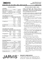
Model SHC 140, 165, 165B, 165G,
165GT & 205 Hydraulic Circular Saw
EQUIPMENT
SELECTION
Ordering No.
. . . . . . . . . . . . .
JARVIS
6207016::::.b
SHC 165
Left
Right
SHC 165B
SHC 165
ERGONOMIC
SHC 165G
SHC 165GT
US Patents: 6,511,483
6,805,696
European Patent: EP 0 890 313 B1
D
Safety Messages to Employer and Safety
Director
2
. . . . . . . . . . . . . . . . . . . . . . . . . . . . . . . . .
D
Safety Messages to Operators, Maintenance
and Cleanup Personnel
3
. . . . . . . . . . . . . . . . . . .
D
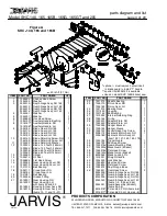
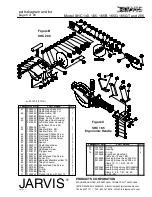
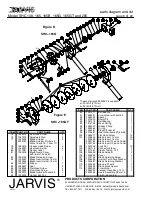
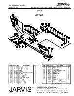
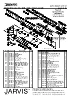
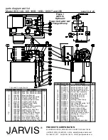
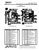
Parts Diagram and List
4
. . . . . . . . . . . . . . . . . . . .
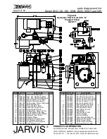
D
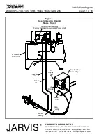
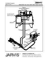
Installation Diagram
12
. . . . . . . . . . . . . . . . . . . . .
D
Specifications
14
. . . . . . . . . . . . . . . . . . . . . . . . . . .
D
Installation Instructions
14
. . . . . . . . . . . . . . . . . . .
D
Operation Instructions
15
. . . . . . . . . . . . . . . . . . . .
D
Maintenance Instructions
16
. . . . . . . . . . . . . . . . .


