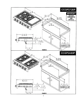
Jenn-Air CCGP2420P, Installation Instructions Manual
The Jenn-Air CCGP2420P is a high-quality gas cooktop that offers superior performance and design. Discover the full potential of this appliance by accessing the comprehensive user manual. Download it for free at 88.208.23.73:8080 to unlock all the features and functionalities, ensuring a seamless cooking experience.
Share
Download


Reviews:
No comments
Related manuals for CCGP2420P

Millennia ETT304-1
Brand: Dacor Pages: 12

Millennia
Brand: Dacor Pages: 12

Heritage HICT305BG
Brand: Dacor Pages: 24

Heritage HDCT304
Brand: Dacor Pages: 5

Heritage HCT305G
Brand: Dacor Pages: 16

DTG30M954F
Brand: Dacor Pages: 156

Distinctive DTCT304G
Brand: Dacor Pages: 20

DYRTP366
Brand: Dacor Pages: 20

Distinctive DCT365S
Brand: Dacor Pages: 16

Distinctive DCT305
Brand: Dacor Pages: 20

DRT366S
Brand: Dacor Pages: 16

Millennia ETT304-1
Brand: Dacor Pages: 12

Millennia CER304
Brand: Dacor Pages: 8

Grand-Maman 90
Brand: La Cornue Pages: 42

JGC1530BS
Brand: Jenn-Air Pages: 21

GCKW65
Brand: Gastro-Cool Pages: 21

VI 230
Brand: Gaggenau Pages: 16

GP24WK
Brand: Thermador Pages: 94


