background image

InstallatIon and staRtUP InstRUCtIons

YORK SOlutiOn

AiR hAndling unitS

Supersedes 102.20-N1 (1108)

Form 102.20-N1 (1109)
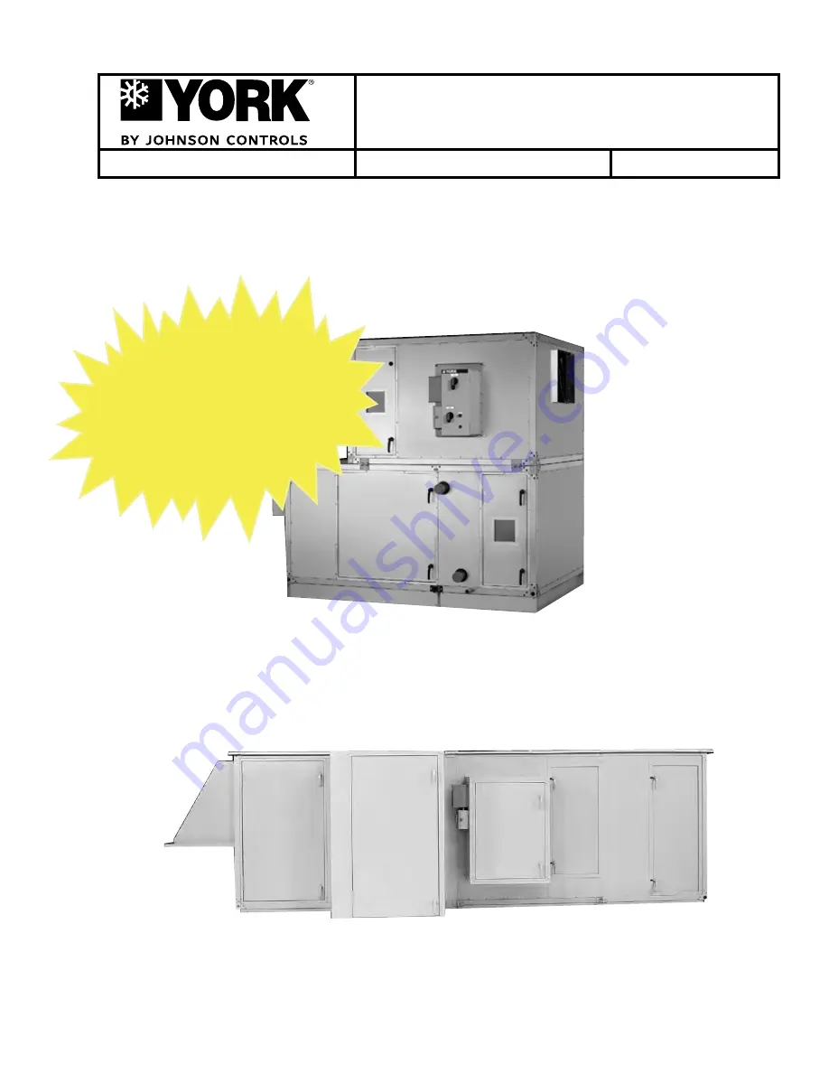
OutdOOR unit

indOOR unit

LD09624

LD09688

YORK SOlutiOn indOOR And OutdOOR MOdElS

Renewal Parts

Form 102.20-RP1

With P/

n contact Balt. Parts

(800) 932-1701

Manufactured or specialty parts 

contact

 Airside (800) 545-7814

Summary of Contents for YORK SOLUTION LD09624

Page 1: ... units Supersedes 102 20 N1 1108 Form 102 20 N1 1109 Outdoor unit Indoor unit LD09624 LD09688 YORK SOLUTION INDOOR AND OUTDOOR MODELS Renewal Parts Form 102 20 RP1 With P N contact Balt Parts 800 932 1701 Manufactured or specialty parts contact Airside 800 545 7814 ...

Page 2: ...with all applicable governmental standards and regulations pertaining to the task in question Safety symbols The following symbols are used in this document to alert the reader to areas of concern CAUTION identifies a hazard which could lead to damage to the machine damage to other equipment and or environmental pollution Usually an instruction will be given together with a brief explanation NOTE ...

Page 3: ...nstruction dirt debris and water DO NOT OPERATE DOORS WHEN UNIT IS NOT ON A FLAT SURFACE Isolate this equipment from pressure testing of water steam gas and air piping Do not test clean and flush piping through coils in this equipment Isolate this equipment from temporary building power Contact local Johnson Controls Service for pur chase of Startup Service with two weeks advance notice Provide cu...

Page 4: ...johnson controls 4 FORM 102 20 N1 1109 THIS PAGE INTENTIONALLY LEFT BLANK ...

Page 5: ...Identification 21 Unit ID Label 21 Skid ID Label 21 Segment Identification Box 21 Loose Component ID Label 22 Filter ID Label 22 Direction of Airflow 22 1 0 pre installation 1 1 RECEIVING 1 1 RIGGING OF INDOOR AND OUTDOOR UNITS 1 1 Off Loading 1 2 Crane And Spreader Bars 1 2 Fork Lift 1 2 Come A Longs or Power Pull 1 2 Shackles 1 3 INSPECTION 1 4 Check For Damage 1 4 Receiver Responsibility 1 4 In...

Page 6: ...7 Installation of Tiered Unit 2 21 Assembly of End Channel Shipping Split 2 23 HOOD INSTALLATION WITH OPTIONAL MIST ELIMINATORS 2 24 OUTDOOR AIR TEMPERATURE AND OR HUMIDITY SENSORS 2 24 ACTUATOR INSTALLATION 2 25 INSTALLATION OF MULTIZONE MZ DAMPERS 2 26 Damper Installation 2 26 Actuator Installation Mutlizone MZ Field Supplied 2 27 INERTIA FAN BASE FILL INSTRUCTION 2 27 HUMIDIFIERS 2 27 UVC EMITT...

Page 7: ...ifier Option Electric 2 43 Humidifier Option 2 43 PIPING CONNECTIONS 2 44 Coil Piping 2 45 Staggered Coils 2 45 Water 2 46 Water Coils Hot Water and Chilled Water 2 46 Hot and Chilled Water Coil Performance 2 46 Water Treatment 2 48 Steam 2 48 Steam Coils 2 48 Steam Distributing Coils 2 48 Steam Control 2 48 Steam Traps 2 49 VIFB and IFB 2 50 Refrigeration 2 54 Direct Expansion Coils DX 2 54 DX Co...

Page 8: ...s 2 66 Installation of 2 Perfectpleat Premium or Premium HM 2 68 Installation of Spring Latches 2 68 Installation of 4 Amair 300x Pleated Filter 2 69 Installation of SH Single Headered Filters 2 70 Installation of Latches 2 70 Installation of a 2 Prefilter In Combination with a Single Header Final Filter 2 70 Installation of Latches 2 70 Installation of a Varicel DH Double Headered Filter 2 71 Ins...

Page 9: ...eed Drive VSD 3 7 Set Up of a Non Factory Mounted VFD 3 7 Check Doors and Latches for Proper Adjustment 3 8 Sheaves 3 8 General Guidelines for Replacing an Adjustable Sheave with a Fixed Sheave 3 8 Energy Recovery Wheel 3 9 Unit Configuration 3 9 Indoor Units 3 9 Outdoor Units 3 9 Start Up Procedure for Energy Recovery Wheel 3 9 Indirect Fired Gas Heat Start Up 3 11 Introduction 3 11 Identify the ...

Page 10: ...johnson controls 10 FORM 102 20 N1 1109 THIS PAGE INTENTIONALLY LEFT BLANK ...

Page 11: ...EPING PAD 2 5 FIG 2 6 CEILING SUSPENDED UNIT 2 6 FIG 2 7 TOOLS TYPICALLY USED FOR ASSEMBLY OF SHIPPING SPLITS 2 7 FIG 2 8 SECOND TIER TIE DOWN FASTENER PACK P n 386 03419 000 2 8 FIG 2 9 BOTTOM RACEWAY SHIPPING SPLIT FASTENER PACKP n 386 03418 000 2 8 FIG 2 10 BASERAIL SHIPPING SPLIT FASTENER PACK P n 386 03417 000 2 8 FIG 2 11 TOP RACEWAY SPLIT FASTENER PACK 2 8 FIG 2 12 PIPE CHASE HOODS SEAM CAP...

Page 12: ...PIPE CHASE TO AIR HANDLER CAULK APPLICATION 2 32 FIG 2 48 INSTALL COVER ANGLE 2 32 FIG 2 49 PROPER POSITIONING OF COVER ANGLE WITH NOTCH ON AIR HANDLER SIDE 2 33 FIG 2 50 PROPER PATTERN FOR INSTALLING SELF DRILLING SCREWS TO COVER ANGLE 2 33 FIG 2 51 BASERAIL COVER APPLICATION 2 33 FIG 2 52 GAS FURNACE FUEL VENTING SYSTEM 2 34 FIG 2 53 GAS FURNACE Condensate drain trap 2 35 FIG 2 54 TYPICAL MOTOR ...

Page 13: ...DO NOT USE THE ABOVE CONFIGURATION 2 58 FIG 2 89 SIX COMPRESSOR YCUL 2 59 FIG 2 90 DRAIN TRAP SHOWING WATER LOCATION DURING DRAW THROUGH OPERATION STAGES 2 61 FIG 2 91 TRAP DETAIL FOR DRAW THROUGH APPLICATION 2 61 FIG 2 92 TRAP DETAIL FOR BLOW THROUGH APPLICATION 2 61 FIG 2 93 COMBINING DRAIN LINES 2 62 FIG 2 94 RECOMMENDED DISCHARGE DUCT ARRANGEMENT WHEN TURNS ARE REQUIRED 2 62 FIG 2 95 RECOMMEND...

Page 14: ...E 3 3 FIG 3 3 ODP OPEN DRIP PROOF 3 3 FIG 3 4 TEFC TOTALLY ENCLOSED FAN COOLED 3 4 FIG 3 5 SPRING ISOLATOR 3 4 FIG 3 6 SEISMIC SNUBBER 3 4 FIG 3 7 EXAMPLE OF SWEEP BALANCE RESULTS 3 7 FIG 3 8 TYPICAL DRIVE KIT DATA TAG 3 8 FIG 3 9 INDOOR UNIT VERTICAL WHEEL 3 9 FIG 3 10 OUTDOOR UNIT HORIZONTAL WHEEL 3 9 FIG 3 11 ENERGY RECOVERY WHEEL PULLEY SIDE 3 10 FIG 3 12 SEGMENT RETAINER 3 10 FIG 3 13 DIAMETE...

Page 15: ... UNIT NOMENCLATURE 18 TABLE 1 1 SPACING REQUIREMENTS FOR OFFLOADING LONG UNITS 1 2 TABLE 3 1 TORQUE FOR TIGHTENING SETSCREWS 3 3 TABLE 3 2 NATURAL GAS PRESSURE REQUIREMENTS INCHES WC 3 18 TABLE 3 3 PIPE SIZE REQUIRED 3 19 Table 3 4 BURNER TEPERATURE RISE 3 23 TABLE 3 5 INSPECTION REQUIREMENTS 3 29 ...

Page 16: ...johnson controls 16 FORM 102 20 N1 1109 THIS PAGE INTENTIONALLY LEFT BLANK ...

Page 17: ... equipment and injury to the installer or operator The YORK Solution features segmented construction and is factory assembled Segment arrangements will vary to suit job application see Fig 1 Heavy gauge galvanized steel is used on the exterior and interior of the unit Access doors are provided for accessibility to the various sections Removable access panels are standard in lieu of doors on Commer...

Page 18: ... stages can be energized as needed Heating Operation Various types of heating may be applied Hot water or steam coils maybe specified typically Electric heat and fuel burner heat are available Cooling Operation Various types of cooling may be utilized Factory mounted chilled water coils or direct expansion refrigerant coils may be specified for the YORK Solution unit HAND IDENTIFICATION Coil conne...

Page 19: ...oil VC Vertical Coil MZ Multizone HEAT SEGMENTS IC Integral Face Bypass Coil IG Indirect Gas Fired Furnace EH Electric Heater ENERGY RECOVERY ER Energy Recovery FILTER SEGMENTS FF Flat Filter 2 or 4 AF Angle Filter 2 4 RF High Efficiency Filter Rigid Filter 12 Bag Filter 21 Mini Pleat Filter 4 HF HEPA Filter INLET SEGMENTS MB Mixing Box FM Filter Mixing Box EF Filter Economizer EE Economizer IP In...

Page 20: ...LLER P 30 51 57 63 69 75 81 87 93 96 99 105 108 111 117 123 Q SWSI PL FAN DIRECT DRIVE w SERVICE DISCONNECT ONLY Q 40 54 60 66 72 78 84 90 96 102 108 114 120 126 132 R SWSI PL FAN DIRECT DRIVE w MOTOR STARTER R 50 57 63 69 75 81 87 93 99 105 111 117 120 123 129 135 S SWSI PL FAN DIRECT DRIVE w VARIABLE FREQUENCY DRIVE S 60 60 66 72 78 84 90 96 102 108 114 120 126 132 138 144 T 75 60 66 72 78 84 90...

Page 21: ...PORATIVE THE DESIGN PRESSURE MARKED ABOVE SHALL NOT BE LESS THAN THE DESIGN PRESSURE MARKED ON THE REMOTE CONDENSING UNIT XTO 108X120 JJRN046A CHTM XT0085 08 179121 01 01 FS CC HM XA IC XA RF EE FR 5 AHU 9 10 460 3 60 _____ _____ 50 72 90 150 25 38 47 5 80 N A N A N A N A 120 1 60 20 20 200 F 50 325 PSI _____ _____ East York 1499 E PHILADELPHIA ST YORK PA 17403 OUTDOOR 117817 COM ELECTRIC HEAT RAT...

Page 22: ...026 32404 009 FLTR VCL_SH 12W_24H_12D 80 85 4 Qty 026 32404 010 FLTR VCL_SH 24W_24H_12D 80 85 16 Qty Spare Filters 026 32406 001 FLTR PERFPLT 30 EFF 12W_24H_2D 8 Qty 026 32406 003 FLTR PERFPLT 30 EFF 24W_24H_2D 32 Qty 026 32404 009 FLTR VCL_SH 12W_24H_12D 80 85 4 Qty 026 32404 010 FLTR VCL_SH 24W_24H_12D 80 85 16 Qty MODEL SERIAL DATE CODE JOB IDENTIFICATION SEGMENT IDENTIFICATION OA Moisture Elim...

Page 23: ...d to avoid damage to the equipment SHIPPEDLOOSEDAMPERS When large units are ordered with MZ seg ments in rear discharge location on the end of the unit the units will ship with the top section hot deck separated In these cases the com plete multizone damper assembly hot deck and cold deck together will ship loose FIG 1 1 RECOMMENDED LIFTING WITH FOUR LIFTING POINTS LD13769 FIG 1 2 RECOMMENDED LIFT...

Page 24: ...t be used to avoid damage to unit If unit does not have lifting lugs use bottom corner connec tors and intermediate raceway lifting lugs Do not use top corner connec tors Unit section weights are furnished on the job submittal Due to the variance in weight of each unit design it is not possible to list unit weights in this instruction The submittal must be referred to when selecting a crane for ri...

Page 25: ... hook and shackle at lifting lugs Figures 1 4 and 1 5 show YORK Solu tion unit without baserails When baserails are present always use all lifting lugs pre mounted on baserails Do not lift by corners FIG 1 6 RECOMMENDED LIFTING WITH BASERAIL LD13766 FIG 1 5 PROPER LIFTING WITH SHACKLE AT LIFTING LUG LD13768 FIG 1 4 PROPER LIFTING WITH SHACKLE AT CORNER LD13767 ...

Page 26: ...ty Receiver is solely responsible for noting freight bill and filling freight claims IMMEDIATLY see Receiving in this section Visible damage should be noted on the signed and dated bill of lading with a request that the carrier inspect the damage within 72 HRS of notification The shipping wrapper must be removed and replaced with a tarp or similar protective covering Any concealed damaged reported...

Page 27: ...pping the sheaves and motor and sealing them with plastic Insert a desiccant to absorb moisture that may penetrate the plastic protection The fan motor windings should be megged at this time and recorded for comparison prior to placing in service If the fan housing was supplied with a drain con nection this plug should be removed to prevent moisture from accumulating in this portion of the fan dur...

Page 28: ...johnson controls 1 6 FORM 102 20 N1 1109 Pre installation FIG 1 7 LONG TERM STORAGE REQUIREMENT FIELD PREPARATION FORM 50 23 NM3 ...

Page 29: ...1 7 johnson controls FORM 102 20 N1 1109 1 FIG 1 8 LONG TERM STORAGE PERIODIC CHECKLIST AND LOGS FORM 50 23 CL3 ...

Page 30: ...johnson controls 1 8 FORM 102 20 N1 1109 THIS PAGE INTENTIONALLY LEFT BLANK ...

Page 31: ...ature with gas heat venting SITE PREPARATION Outdoor Units Site Prep Location of unit s should be away from building flue stacks or exhaust ventilators to prevent possible introduction of contaminated air through the outside air intakes see Fig 2 1 for service clearances Allow sufficient space around the unit for removing the access panels and various parts of the unit A minimum clearance equal to...

Page 32: ...rfectly flat plane Curb The curb which supports the unit will be shipped unassembled It will be necessary to assemble the curb parts on the job site Assembly drawing and a hardware package are shipped with each curb package It is important the curb be installed square If applicable ensure pitch orientation is correct This Curb Assembly and Installation Instruction is typical Use it in conjunction ...

Page 33: ...b However the gasket should not be used as a vibration isolator where the prevention of noise and vibration transmis sion into the building is critical When unit is shipped in sections the curb gasket is to be replaced with caulk provided by contractor 5 After verifying curb is square and level tighten all bolts and then anchor as appropriate If bolts are tightened after anchoring curb will be pul...

Page 34: ...ON TO UNIT CURB A A D A 2 C B 1 7 8 1 1 2 LEFT HAND PIPE CHASE CURB SUPPORTS as required RIGHT HAND PIPE CHASE PIPE CHASE SECTION VIEW SECTION A A 2 UNIT ROOF CURB CURB REST 1 7 8 2 x 4 NAILER UNIT WALL UNIT RACEWAY Curb for Pipe Chase Note 1 ROOF CURB CURB REST 2 x 4 NAILER NOMINAL STANDARD RACEWAY WALL PANEL STANDARD BASE RAIL STANDARD RACEWAY WALL PANEL Note 1 ROOF CURB Note 2 CURB REST CURB GA...

Page 35: ...must be installed in such a manner as to provide enough elevation for properly designed condensate traps See Section 2 Piping Connections Condensate Drain Trap FIG 2 3 NO BASERAIL HOUSEKEEPING PAD REQUIRED TO ACCOMMODATE TRAP HEIGHT LD05372 Floor The floor must be flat and level Housekeeping Pad The housekeeping pad must be flat and level see Fig s 2 3 2 4 and 2 5 FIG 2 4 NO HOUSEKEEPING PAD BASER...

Page 36: ...g Structure Positioned Perpendicular to Airflow The units must be supported at a minimum in the following locations Both ends At each shipping split Upstream and downstream of each cooling coil segment Under heavy components like fans attenuators and heating segment Do not obstruct door operation filter access piping electrical or control connections with suspension mem bers FIG 2 6 CEILING SUSPEN...

Page 37: ... not provided by Johnson Controls When unit is shipped in sections the gasket provided with the curb is to be replaced with caulk pro vided by contractor Gaskets on curbs can pose a problem when sliding sec tions together for the final connection of each shipping split Structure Positioned In the Direction of Airflow The unit base must be supported continuously on both sides of the unit UNIT INSTA...

Page 38: ...PPING SPLIT FASTENER PACK P n 386 03417 000 4 each per pack LD11029A LD11030A LD11032A 3 8 Nut 3 16 Allen Wrench 3 8 Flat Washer 3 8 Lock Washer 3 8 x 3 4 Button Head Screw Size 3 16 Allen Wrench 1 2 x 5 1 2 Hex Cap Screw 2 56 ID x 1 38 OD Flat Washer 2 Lock Washer 2 1 2 Hex Nut FIG 2 11 TOP RACEWAY SPLIT FASTENER PACK P n 386 04747 000 2 each per pack LD13349 Bracket p n 086 11146 001 Ship Loose ...

Page 39: ...w Washer Gasket Tek Screw P N 021 30530 052 for Outdoor Roof Roof Seam Cap Outdoor ROOF SEAM CAP Apply 2 Gasket Caulk Apply 2 Gasket Caulk 1 4 x 2 Neoprene Gasket P N 028 15954 010 1 4 14 x 1 Hex Head w Washer Gasket Tek Screw P N 021 30530 052 PIPE CHASE SEAM CAP 1 4 14 x 1 Hex Head w Washer Gasket Tek Screw P N 021 30530 052 1 4 x 2 Neoprene Gasket P N 028 15954 010 PIPE CHASE TRIM ANGLE HOOD Ap...

Page 40: ...evices and sundries are shipped loose DO NOT touch UV Lamps tubes with bare hands or leather gloves as oils will damage the tubes Use clean cotton rags clean jersey or latex gloves to handle the lamps tubes LD13788 DAMPER SHAFT EXTENSION KIT P N 026 33715 002 CORNER CONNECTOR HOLE PLUG P N 021 19568 000 GAS FURNACE FUEL VENTING PARTS UV LIGHT TUBE UV LIGHT TUBE UV LIGHT TUBES to be installed by co...

Page 41: ...883 0 Outdoor Only 1 4 X 2 X 25 NEOPRENE GASKET P N 028 15954 010 3 16 X 3 4 X 40 BUTYL TAPE P N 013E 03327 010 1 4 X 3 4 X 35 NEOPRENE GRAY GASKET P N 028 11873 010 1 4 14 X 1 PHILLIPS PAN HEAD SELF DRILLING SCREW P N 021 19560 000 1 4 14 X 1 HEX HEAD SELF DRILLING SCREW W EDPM WASHER P N 021 30530 052 SPARE FAN BELT Attached to Fan POLYURETHANE CAULK P N 013 02966 011 GREY P N 013 03317 040 CHAM...

Page 42: ...BOTTOM SPLIT RACEWAY BASERAIL W LUG CURB REST CURB REST FIG 2 16 SHIPPING SPLIT EXAMPLES FOR EXPANDED CABINET REMOVABLE LIFITING LUGS WELDED CHANNEL FILLER Remove lifting lugs before assembling shipping splits Retain bolts etc and use to secure assembled shipping split 3 4 ZINC HEX NUT use from Lifting Lug no flat or lock washers required BASE CHANNEL BASE CHANNEL 3 4 GR5 HEX BOLT use from Lifting...

Page 43: ...16 for Shipping Split Examples If applicable remove metal bracket screwed to the cross channel and wood shipping blocks before assembling shipping splits When unit is provided with shipping splits use construction grade caulk not provided in place of curb top gasket Apply the caulk on top of curb just before each section is placed on the curb Apply the caulk with a 1 2 diameter bead to assure seal...

Page 44: ...om 3 5 square to 3 5 square Apply this gasket 1 4 from outside edge of mating surface nearest to exterior of air handler This is to allow for a 1 4 bead of caulk Refer to Fig 2 17 FIG 2 17 APPLYING GASKET g Apply a thick bead of caulk not provided to curb top surface only where the first section will be placed 2 Place the first section on the curb while position ing it so that the overhanging curb...

Page 45: ...re clear b Guide the top raceways together by placing rods or drift pins through the holes in the top guide angles When the raceways are close enough install the long bolts provided c Guide the bottom raceways together using rods or drift pins through the bolt holes in the lifting lugs on opposite sections Do this on each side of the unit simultaneously d If any difficulty aligning due to racking ...

Page 46: ...nts using 1 4 14 x 1 hex head screws provided Painted seam caps are applied over the joints on the sides and roof of the exterior and galvanized seam caps are applied on the floor of the interior only If a roof seam cap has a tab on one end only the end without the tab goes above the pipe chase location 16 Repeat this procedure for each additional section to be placed in making up the complete uni...

Page 47: ...ring the assembly process 1 Before placing sections a Verify the correct sections and orientation of each section b Remove cross brace s shipping supports from each section s shipping split c Remove plastic shipping covers and their supports d Make sure all wiring and or control tubing connection pig tails are secured out of the path of the shipping split mating surfaces to prevent damage e Apply ...

Page 48: ...n in its final position and anchor or block it before placing the next section see Fig 2 25 After wiring connections are made and before proceeding with assembly the top shipping split angle will need to be removed and repositioned see Fig 2 24 Remove Shipping Split Angle after completion of wiring and tubing placement and reposition before proceeding with assembly of shipping splits Remove Shippi...

Page 49: ...al and control con nections from section to section and ensure that they will be accessible after the sections are joined If any will not be accessible assemble the electrical connectors and or pneumatic tubes each according to their labels before joining of sections is complete Refer to Fig 2 27 LD14265 WELDED CHANNEL FILLER BASE CHANNEL REMOVABLE LIFITING LUGS Remove lifting lugs before assembli...

Page 50: ... If any difficulty aligning due to top and bottom not pulling together simultaneously apply shims under the unit sections as needed to compensate for uneven placement area 8 Complete pulling the sections together 9 Fasten bottom lifting lugs together with 1 2 x 4 bolts provided See Fig 2 28 10 Fasten top raceway brackets with 1 2 x 5 1 2 bolts 11 Apply 1 4 x 2 foam gasket to the underside of the s...

Page 51: ...ry because the top panel of the bottom tier is slightly recessed below the height of its raceways g If top tier has shipping splits refer to Installing Multiple Piece Indoor Unit for correct assembly procedure TOP RIGHT RACEWAY TOP LEFT RACEWAY BOTTOM TIER TOP PANEL TOP TIER PLACE FIRST LAYER OF GASKET FROM RACEWAY TO RACEWAY PLACE SECOND LAYER OF GASKET OVER FIRST LAYER AND OVER RACEWAYS FIG 2 31...

Page 52: ... accessible after the sections are joined If any will not be accessible assemble the electrical connectors and or pneumatic tubes each according to their labels before joining the top and bottom tier 7 Lower the top tier onto bottom tier so that mount ing brackets mate Guide brackets together using rods or drift pins through the bolt holes see Fig 2 32 8 Carefully place each section of the top tie...

Page 53: ... 3 Remove screws in raceway corners at ends of all segments joining together as shown in Detail A of Fig 2 33 4 Clean the metal surface where gasket is to be applied with mineral spirits or rubbing alcohol 5 Apply 1 4 x 2 neoprene gasket to all raceway mating surfaces of one mating section Include two gaskets side by side on intermediate raceway surfaces large units 6 Ensure that the sections are ...

Page 54: ...ut them through their respective penetration to the exterior and mount them to the bracket provided FIG 2 34 HOOD INSTALLATION WITH OPTIONAL MIST ELIMINATORS LD13783 Apply Caulk Apply Butyl Clip Mist Eliminator or Filter HOOD INSTALLATION WITH OPTIONAL MIST ELIMINATORS See Ship Loose Parts for identifica tion of gaskets and hardware 1 Identify correct hood and respective location see example on Fi...

Page 55: ...on required to actuate the damper Damper actuator rotation will always be opposite the spring return rota tion ACTUATOR INSTALLATION See Fig 2 35 1 Remove the bearing plate from the damper frame and jackshaft 2 Slide the damper actuator onto the open end of the shaft making sure that the proper spring return position on the face of the actuator matches the damper shafts rotation If not then reinst...

Page 56: ...6 03474 516 AIR FLOW SHAFT EXTENSION KIT 026 33715 002 HOT DECK DAMPER FACTORY INSTALLED COUPLER COLD DECK DAMPER MOUNTING FLANGES MOUNTING FLANGES ACTUATOR 025 39032 002 SCREW 025 19515 000 MTG BKT 086 03474 516 HOT DECK DAMPER SHIPPING PLATE AIR ENTERING SHIPPING PLATE AIR LEAVING COLD DECK DAMPER EXTENSION PIN LD12029A ACTUATOR P N TORQUE BRACKET SMALL 025 39032 002 35 IN LBS 086 03474 516 LARG...

Page 57: ...nt discharge through end of unit always mount the actuators on the top of the up per hot deck Do not allow duct insulation to restrict damper blades or external linkage Direct coupled actuators are recommended Duct connections are to be made at the zone dividers without damper blade restriction INERTIA FAN BASE FILL INSTRUCTION Inertia fan bases are pre engineered according to fan and motor size E...

Page 58: ...is responsible for installing UV Lamps tubes and connecting a 120 volt power supply The YORK Solution factory provides internal wiring with a magnetic door safety switch a lockable disconnect switch with Press to Test pilot light and a latching circuit that has to be manually re energized on the air handler exterior after a door has been opened and closed This is all pre wired The UV Lamps tubes a...

Page 59: ...ingle connection piped to the negative port of a factory mounted transducer on the fan wall The positive port is left open to the fan section Wiring is not provided to the transducer unless factory packaged controls were selected Air Measuring at Unit Inlets AMS 60 used on Indoor YORK Solution air handlers usually to measure outside air This can be provided with one or two pairs of positive and ne...

Page 60: ...HANG Apply gasket AIR HANDLER Apply gasket AIR HANDLER LD11564 PIPE CHASE INSTALLATION See Ship Loose Parts to identify gaskets and hardware items Pipe chase should be installed before piping is connected Tools Required Screw Gun Complete set of mechanics hand tools Materials Required Shipped loose package containing 1 4 14 x 1 Self drilling Screws w gasket Caulking 1 4 x 2 Neoprene Gasket When un...

Page 61: ...verlap vertical gaskets in all four corners 3 Install vertical gaskets first Install vertical gaskets first 1 Install horizontal gaskets second Install horizontal gaskets second 2 3 3 PIPE CHASE PIPE CHASE LD12560A FIG 2 43 PIPE CHASE BASERAIL TO UNIT BASERAIL INSTALLATION RIVET NUT installed by factory BASERAIL COVER installed later see Fig 2 44 PIPE CHASE BASERAIL UNIT BASERAIL LOCK WASHER typ 6 ...

Page 62: ... vertical corners of pipe chase and unit wall Notch on cover angle must be on the air handler side see Fig 2 48 AIR HANDLER PIPE CHASE Cover Angle shown with gasket side out AIR HANDLER PIPE CHASE Install Cover Angle between Air Handler and Pipe Chase before caulk dries Install Cover Angle between Air Handler and Pipe Chase before caulk dries Cover Angle shown with gasket side out FIG 2 48 INSTALL...

Page 63: ...B PIPECHASE BASERAIL COVER APPLY CAULK AROUND PERIMETER OF PART BEFORE APPLYING TO BASERAIL SEAM Caulk Application Cover Installation 1 CAULK PERIMETER OF COVER AS SHOWN BELOW 2 APPLY COVER TO BASERAIL SEAM PIPECHASE BASERAIL UNIT BASERAIL Put notch on cover angle on Air Handler side Put notch on cover angle on Air Handler side AIR HANDLER AIR HANDLER PIPE CHASE PIPE CHASE FIG 2 49 PROPER POSITION...

Page 64: ...TEP 4 0 43 CLEARANCE 6 L SLIP JOINT HAT CHANNEL GAS FURNACE WITH CASING FIG 2 52 GAS FURNACE FUEL VENTING SYSTEM LD13326 NOTES 1 On outdoor Air Handling units the external flue vent piping parts above the pipe chase are factory installed on units having an overall height of less than 102 including the vent piping 2 Outdoor Air Handling units over 102 high will have the external vent piping parts s...

Page 65: ...it deposits of solids in the condensate drainage system 8 Provide the ability to prime the trap During initial and seasonal start up trap inspection and priming is required Condensate in the trap will evaporate during long periods of non use Condensate Drain Arrangement The YORK Solution Indirect Fired gas heat exchanger has the potential to create highly acidic condensation particularly during ex...

Page 66: ...le and voltage are stamped on the nameplate of each component Electrical conduit connections made to exposed boxes on units should be made on the bottom of the box Installation should comply with code requirements Outdoor installation must be made watertight The installing contractor is responsible for electrical conduit penetrations through the building roof Penetrations through panels must be se...

Page 67: ...xhaust Fan A motor connection diagram may be found on the inside of the motor terminal box or on a tag attached to the motor Be sure to make a flexible conduit connection at the motor to permit fan belt adjustment and movement of spring isolated fan assembly Refer to Motor Data Nameplate for all motor specifications see Fig 2 54 FIG 2 54 TYPICAL MOTOR DATA NAMEPLATE 00495VIP Energy Recovery Wheel ...

Page 68: ...n 5 Field Penetrations for Piping and Electrical Connections Make power connections per wiring diagrams provided inside burner control panel Also see generic diagrams in IOM Section 6 Refer to Fig 2 56 and Fig 2 57 for Gas Burner component locations Terminal Strip for Power and Controls FIG 2 57 MAIN POWER AND CONTROL PANEL W COVER OPEN LD11597 FIG 2 56 GAS BURNER COMPONENT LOCATIONS LD11596B Insi...

Page 69: ...ked and re tightened if needed The danger of a poor connection is overheating and component failure DO NOT PENETRATE any main or auxiliary drain pan Electric Heat Option Wiring of this device is the responsibility of the installer if Single Point Power was not selected Available Power Options 460V 3PH 208 230V 3PH 380V 3PH 575V 3PH Electric Heat Disconnect Switch Options Fused Disconnect Non fused...

Page 70: ...inned tubular heaters 80 F 3 Sufficient working space must be provided per paragraph 110 26 of the NEC 4 This electric heater is not designed for or intended to be used for temporary heat prior to system startup balancing MECHANICAL INSTALLATION 1 All heaters will contain an adjustable airflow switch in the heater control panel This switch will be preset to close at a differential pressure of appr...

Page 71: ...NIT POSITIVE PRESSURE AIR BLOWN THROUGH HEATER NEGATIVE PRESSURE AIR DRAWN THROUGH HEATER BLOWER BLOWER HEATER HEATER AIRFLOW PICK UP T UBE TOWARDS BLOWER ATTACHED TO HIGH PORT OF AIRFLOW SWITCH PICK UP TUBE TOWARDS BLOWER ATTACHED TO LOW PORT OF AIRFLOW SWITCH AIRFLOW C NO NC HIGH PORT LOW PORT MOUNTING BRACKET LD14268 LD14270 ...

Page 72: ... 80 100 3 184 230 4 0 16 12 92 115 2 204 255 250 24 10 104 130 1 228 285 300 40 8 120 150 0 248 310 350 52 65 6 140 175 2 0 268 335 400 68 85 4 160 200 3 0 304 380 500 7 When connecting heaters with more than one stage wire stage No 1 so that it is the first stage on and the last stage off 8 The heater must be wired so that it cannot operate unless air is flowing over it This can be accom plished ...

Page 73: ...o prevent air and water leakage see IOM Section 5 Penetrations and Grommet Details Field provided disconnects must provide circuit protection according to the humidifier nameplate All field wiring to the humidifier must be in accordance with NEC and local codes and by laws FIG 2 62 TYPICAL HUMIDIFIER PANEL LAYOUT LD11726 FIG 2 63 SUPPLY POWER KNOCKOUTS Humidifier Option Control wiring diagrams are...

Page 74: ...chase floor must be flashed and sealed Penetrations through panels must be sealed see IOM Section 5 Penetrations and Grommet Details Where piping is insulated insulation should not be installed until after the flashing has been completed Pipe chase should be installed before piping is connected FIG 2 65 PIPE CHASE ENCLOSURE All dimensions are approximate and not certified for construction Usable w...

Page 75: ...g may cause damage to the header A backup wrench should be firmly held on the coil connection so that in tightening the connecting piping the torque is not transmitted to the coil header thus damaging the coil connection Application Notes All connections are male piping threadexceptDXcoils whicharesolder Drainandvent taps on water coils are pipe thread shipped with plugs installed These taps are i...

Page 76: ...ee Figs 2 68 2 69 and 2 70 for typical piping diagrams FIG 2 68 CHILLED WATER COIL CONNECTIONS RETURN SUPPLY RETURN CHILLED WATER SUPPLY REDUCING TEE STRAINER CHILLED WATER RETURN GLOBE VALVE GLOBE VALVE GATE VALVE GATE VALVE W HOSE BIB 3 WAY CONTROL VALVE UNION UNION PT PLUG PT PLUG DRAIN ECCENTRIC REDUCER COIL VENT COIL SUPPLY LD12939 Example NOT for construction Hot and Chilled Water Coil Perfo...

Page 77: ...T COIL SUPPLY DRAIN FIG 2 69 HOT WATER PIPING 2 WAY VALVE FIG 2 70 HOT WATER PIPING WITH DIVERTING VALVE LD13791 LD13792 RETURN SUPPLY RETURN HOT WATER SUPPLY STRAINER HOT WATER RETURN GLOBE VALVE GLOBE VALVE GATE VALVE GATE VALVE W HOSE BIB UNION PT PLUG PT PLUG REDUCING TEE 3 WAY CONTROL DIVERTING VALVE 1 Inlet 2 Outlets UNION COIL VENT COIL ECCENTRIC REDUCER DRAIN SUPPLY Example NOT for constru...

Page 78: ...temperature Consult the submittal issued for each specific unit for above information Steam Distributing Coils Do not bush or reduce the coil return pipe size Use a full size return pipe to the bottom of a dirt pocket The supply pipe may be reduced at the coil connection if necessary Install the coil casing level with the return down A coil must be sufficiently elevated to allow a 12 inch minimum ...

Page 79: ... below the coil return connection and even lower when freeze protection is required Do not attempt to lift condensate modulated steam supply FIG 2 71 STEAM COIL PIPING ARRANGEMENTS VENT TO ATMOSPHERE CLOSE TO UNIT NOT ON VACUUM SYSTEMS DRIP TRAP FOR END OR LOW POINT OF SUPPLY MAIN SUPPLY MAIN RETURN M AIN STEAM COIL PITCHED IN CASING 12 MIN DIRT POCKET FULL SIZE OF COIL CONN VACUUM BREAKER 1 2 CHE...

Page 80: ...g fittings VIFB Warranty will be voided should return piping on lower header inlet and return on two row header not include flexible connector s and if lower header s bolts are not removed prior to use See IFB VIFB manufacturer s IOM for additional piping details Factory does NOT pipe connections to unit exterior Below 35 F theVerticalTube Integral Face and Bypass VIFB or Integral Face and Bypass ...

Page 81: ...ir capable applications locate low limit at least 24 downstream of leaving edge of VIFB IFB casing Low limit element must cross both face and bypass areas parallel to headers Shipping Bolts VIFB Only Return steam condensate headers or hot water supply and return headers are securely bolted to lower mounting brackets to prevent damage to header and tubes during shipment and piping of the coils Thes...

Page 82: ...OR IFB FLEXIBLE CONNECTOR HOT WATER RETURN SUPPLY HOT WATER VIFB COIL FLOW AIR 3 4 19 1mm AUTOMATIC AIR VENT IN TOP HEADER DRAINS FIG 2 74 HOT WATER PIPING FOR 2 ROW COIL VIFB LD09632 FLO W AIR HOT WATER RETURN 3 4 19 1 AUTOMATIC AIR VENT IN TOP HEADER DRAIN HOT WATER SUPPLY LD09633 ...

Page 83: ...RAP 1 2 12 7 THERMOSTATIC TRAP FLOW CONDENSATE NON VENTING TRAP AUTOMATIC 3 4 19 1 FOR AIR REMOVAL AIR VENT FLOW AIR FLOW AIR 8 203 2 MINIMUM 8 203 2 304 8 VENTING VALVE 1 2 12 7 15 VACUUM BREAKER CHECK NOTE DIMENSIONS ARE IN INCHES DIMENSIONS IN PARENTHESIS ARE IN MILLIMETERS FLEXIBLE CONNECTOR INSTALLED PARALLEL TO COIL HEADER AND AS CLOSE AS POSSIBLE TO COIL CONDENSATE CONNECTION AS CLOSE AS PO...

Page 84: ... detrimental to the refrigerant system Until the piping is complete recap the system and charge with nitrogen at the end of each workday Clean all piping connections before brazing joints The orientation of the refrigerant distributor is not critical but the distributor tubes must not be kinked or bent in a non uniform configuration For this and other piping and sundry tips refer to Fig 2 77 The o...

Page 85: ...e the capacity between the coils Face Split On a face split coil the circuiting is divided between two separate coils In field erected systems this arrangement may suffer from TXV superheat control problems and compressor reliability At low airflow low load situations the TXV may have difficulty controlling system superheat Air stratification poor humidity control and condensation on downstream co...

Page 86: ...nce is needed to convert split face to full face operation H1 H2 H1 D2 D1 D1 1 Distributor Circuit 2 Distributor Circuits 50 50 Interlaced FIG 2 80 NON STACKED COIL DESIGN STANDARD LD09143A FIG 2 79 NON STACKED COIL DESIGN SQ SPECIAL LD09144A H1 D1 D2 H2 D3 D2 D1 H4 H2 H1 D1 D2 H3 D4 D3 H1 H2 H3 H4 H5 H6 H7 H8 D2 D1 D3 D4 D5 D6 D7 D8 H1 H2 H3 H4 D1 D2 D3 D4 D1 H1 H2 D2 2 Distributor Circuits Face ...

Page 87: ...rant circuit Fig 2 85 each TXV should be sized to handle half of the capacity of the refrigerant circuit and the LLSV should be sized to handle the full capacity of the refrigerant circuit FIG 2 83 STACKED COIL CIRCUITING LD09147A Two Circuits NOT Recommended Four Circuits Recommended 2 4 1 3 1 2 FIG 2 82 STACKED COIL DESIGNS SQ SPECIAL LD09146 H1 H2 H3 H4 H5 H6 H7 H8 D2 D1 D3 D4 D5 D6 D7 D8 H1 D1...

Page 88: ...2 FIG 2 88 DO NOT USE THE ABOVE CONFIGURATION When sizing TXV s each TXV must be sized for the refrigerant circuit tonnage divided by the number of DX coil liquid distributors The TXV should be equal to or smaller than the calculated value The first three compressors see Fig 2 89 would be tied into LLSV1 TXV1 and TXV2 This would provide full face control of the coil at even the lowest cooling load...

Page 89: ...K DX coils may be ordered for field application of a hot gas bypass valve The connection may be made through a tee installed in the field between the expansion valve and distributor The system balance point and control adjustments must assure compressor cooling and avoid excessive compressor cycling Refer to Form 50 40 ES3 Section 3 Maintaining Adequate Airflow An electrical interlock between the ...

Page 90: ...ely a lower duct static pressure indicates a need for increased zone airflow therefore the supply fan volume increases in response The change in supply air volume is accomplished using a Variable Frequency Drive or similar device In the air handling unit a decrease in airflow through the DX coil will result in a corresponding decrease in the suction gas pressure while an increase in airflow will r...

Page 91: ...liary drain pans may not require traps If the trap is not in constant use the water seal may evaporate causing air passage into or out of the air han dler In such cases it is recommended to cap the drain in a manner that al lows opening or closing of the drain depending on its use Condensate Drain Piping The majority of cooling coils are located in the units so that the supply air is drawn through...

Page 92: ...nnection Guidelines See Fig 2 94 Duct connections to the unit may be made directly except when the unit has external isolation Then duct connections should be flexible material and should be installedsotheyaresufficientlyloose Ductconnections should be designed and installed according to AMCA Standards 200 and 201 as a minimum Duct turns and transitions must be made carefully to hold friction loss...

Page 93: ...e from inside the unit access may have to be from inside the duct or sleeve Raw or straight edge ducts can be connected with self drilling screws directly to the unit with gasket or sealant between unit and duct LD14087 Duct Connections Ducts must have positive seal to unit openings Installer is responsible for providing ductwork to include baserail height for curb mounted units All duct work is t...

Page 94: ...such applications there should be a sound absorption chamber installed near the unit return air inlet Various reference sources are available regarding acoustic design Front and Rear Discharge Outdoor Unit Duct Installation Roof penetrations by ducts should utilize counter flashed curbs Typical arrangements are shown in Fig 2 96 All penetrations into ducts should be sealed watertight Attachment of...

Page 95: ... which case the filter clips will be attached to the filter racks inside the unit Filter clips are not required for side load filter arrangements Contractor is responsible for installation of filters Contractor is responsible for freight claim if filters arrive damaged Other issues such as size type spares replacements or quantity should be addressed with the Johnson Controls Sales office or proje...

Page 96: ...tion with a Double Header Final Filter Used with 4 Prefilter in combination with a Double Header Final Filter Typically when filters are by others so are the filter clips Used to attach HEPA Filters to Holding Frame P N 026 35778 000 P N 026 35778 000 P N 026 35778 007 P N 026 35778 007 P N 026 35778 006 P N 026 35778 000 4 11 16 4 11 16 P N 026 36339 000 P N 026 36339 000 4 11 16 P N 026 36399 00...

Page 97: ...26 36339 000 X FILTER FRAME 24X24 16 ga Galvanized P N 026 35778 007 026 35778 000 X P N 026 35778 006 026 36339 001 X P N 026 35778 007 026 35778 008 026 35778 000 X P N 026 35778 006 026 36339 000 X Single Filter Application 2 PerfectPleat Premium or Premium HM 4 AmAir 300X VariCel SH or DriPak 2000 VariCel DH FILTER FRAME 12x24 16 ga Galvanized P N 026 35778 000 X X P N 026 35778 007 X P N 026 ...

Page 98: ... end of the latch between the two 2 knockouts furthest from the corner 2 Using a moderate amount of pressure force the latch over the third knockout 3 The latch installation should now be complete The latch should now be trapped within the three 3 knockouts but should be able to freely rotate see Fig 2 99 Fig 2 99 Correctly installed latch P N 026 35778 000 LD010171 4 Repeat the installation proce...

Page 99: ...ominal 4 filters Installation of Spring Latches 1 Insert the straight end of the latch between the two 2 knockouts furthest from the corner 2 Using a moderate amount of pressure force the latch over the third knockout 3 The latch installation is now complete The latch should now be trapped within the three 3 knockouts see Fig 2 101 Repeat the installation process with the remaining latches Fig 2 1...

Page 100: ...H or DriPak 2000 filter into 16 ga galvanized holding frames Latches needed for these applications are four 4 P N 026 35778 000 as shown in Fig 2 98 A single latch should be installed at each of the four 4 corners of the frame The latch fits into the set of knockouts which consists of two 2 rows of three 3 knockouts The row of knockouts closest to the gasketing should be used for nominal 1 filters...

Page 101: ...f a Varicel DH Double Headered Filter These instructions are for the installation of a VariCel DH filter nominal 12 deep double header into 16 ga galvanized holding frames The latches needed for this application are four 4 spring latches P N 026 35778 006 as shown in Fig 2 98 Two latches should be attached on each side of the filter frame The latches should only be installed two 2 per side of the ...

Page 102: ...are for installing either a 2 or 4 prefilter typically PerfectPleat Premium or Premium HM pleated filters used in combination with a VariCel DH nominal 12 deep final filter into 16 ga galvanized holding frames Two sets of latches are needed for these applica tions Four 4 spring latches P N 026 35778 006 are used to hold the VariCel DH into the frame In addition four 4 prefilter latches P N 026 363...

Page 103: ...f the prefilter latch and spring it so that it fits over the edge of the prefilter Repeat with the remaining latches After all remaining prefilter latches have been placed around the prefilter the finished assembly should look like that in Fig 2 115 Fig 2 113 Position prefilter in front of the final filter 2 w 026 36339 000 latch shown LD010165 Fig 2 114 Spring the end of the latch so that it fits...

Page 104: ...See Fig 2 119 In the event excessive clamping pres sure is applied the individual cells in the gasket material can be fractured causing the gasket to relax allowing leakage FIG 2 116 HEPA FILTER FRAME CROSS SECTION VIEW LD06647A 2 2 MAIN RUNNER PERIMETER EXTRUSION T SECTION PERIMETER SECTION TYPE H 2 Visual Control Filter Clamps See Fig 2 117 HEPA Filter Applications Visual Control clamps are desi...

Page 105: ...ION PERIMETER SECTION LD09657 FIG 2 118 HEPA FILTER INSTALLATION FIG 2 119 WELDED BEVEL SEAL FILTER INSTALLATION LD06646A BEVEL SEAL FRAME BEVEL RECESSED SEALING SURFACE DUCTWORK SPRING AIRFLOW GASKET CELL SIDE CELL SIDE VISUAL CONTROL CLAMP ADJUST BOLT HEAD FLUSH WITH CLAMP BEVEL SEAL FRAME PERIMETER EXTRUSION MEDIA PACK ...

Page 106: ...johnson controls 2 76 FORM 102 20 N1 1109 THIS PAGE INTENTIONALLY LEFT BLANK ...

Page 107: ... dampers With smoke dampers closed During a fire alarm or smoke purge test Any airflow restriction greater than normal Fluctuating or incorrect voltage power supply While it is a common practice to oper ate the fan as soon as possible air movement during construction is al ways preferred by contractors on the job site the incomplete ductwork and missing diffuser grilles will greatly reduce air res...

Page 108: ...0 NOM1 For VFD equipped air handlers refer to the VFD literature for additional start up requirements 1 Verify equipment received as ordered 2 Check for damage to the interior and exterior of unit 3 Verify unit installed on flat and level surface 4 Ensure terminal screws and wiring connections secure in control electric and Air Modulator pan els 5 Verify air hoods field installed properly 6 Verify...

Page 109: ... properly lubricated see Fan label or IOM Section 4 Fan Bearing Lubrica tion 4 Belts and Sheaves a Verify sheaves properly aligned and tight on shaft Improper sheave alignment and belt tension are potential causes of excessive noise and vibration as well as shortened belt and bearing life see IOM Section 4 Sheaves Alignment b Check belt tension If not familiar with the process see IOM Section 4 Be...

Page 110: ...r frame for correct height and that the frame is level 2 To adjust isolators see Fig 3 5 First loosen cap screws on top of adjustment bolt Then turn adjusting bolt Next check operational height and level of frame Repeat this procedure until operational height and frame is level Finally tighten cap screws See IOM Section 5 Isolator Adjustment for additional instructions 3 Verify the fan is aligned ...

Page 111: ...ator or crank arm on jackshaft open dampers and retighten actuator or crank arm Field is responsible for adjustments IAQ START UP Temporary Operation This equip ment should not be operated until after complete Start up as outlined in this guide Do not allow the unit to run on temporary power that is not reliable and could be off on periodically or rapidly Also protect it from irregular voltages an...

Page 112: ...nd Exhaust Air Dampers Position the damper blades so that they will be closed with power off This will be the dampers spring return position Note whether the damper shaft is rotated fully clockwise or counter clockwise With the actuator shaft clamp tightened to the damper jackshaft and the damper shaft is completely rotated to its proper position manually operate the actuator to its fully actuated...

Page 113: ... does not run at resonant frequencies Improper adjustment may damage the equipment To determine which speeds are detrimental to the YORK equipment refer to the document 058 008 002 supplied with the YORK Solution air handler This information can also be found on the label located on the blower housing see Fig 3 7 This document lists any frequencies and the bandwidths that need to be jumped skipped...

Page 114: ... Sheave Measure the outside diameter of a belt while it is seated into at least one half the circumference of an adjustable sheave groove Use this measure ment as the sheave pitch diameter Order a sheave or sheave and bushing combination that matches pitch diameter belt cross section and bore size Order a sheave of good quality and require that it is prebalanced Reference Airside Parts phone 800 5...

Page 115: ...orizontal see Fig 3 9 Outdoor Units All outdoor units will accommodate horizontal Energy Recovery Wheel segments in a low profile single unit arrangement see Fig 3 10 RETURN AIR MIXING BOX FILTER ENERGY WHEEL EXHAUST FAN FILTER MIXING BOX OUTSIDE AIR SUPPLY FAN HEATING COIL COOLING COIL ELEVATION VIEW SUPPLY FAN FILTER RETURN AIR EXHAUST FAN EXHAUST FAN E A BYPASS O A BYPASS ENERGY WHEEL OUTSIDE A...

Page 116: ...O REMOVE TO ADJUST DIAMETER SEAL 2 Before applying power to drive motor confirm wheel segments are fully engaged in wheel frame and segment retainers are completely fastened see Fig 3 12 3 With hands and objects away from moving parts activate unit and confirm wheel rotation Wheel rotates clockwise as viewed from the pulley side 4 If wheel has difficulty starting turn power off and inspect for exc...

Page 117: ...ide of the burner control door Identify the Unit Type Two types of Indirect Fired gas burners are used on YORK Solution Air Handlers The Powerflame series and the Eclipse series The Powerflame series offers a turndown modulating ratio of 3 1 or 10 1 The Powerflame is easily identifiable by the motorized gas valve with external linkage connecting the air dampers on the burner air inlet The Eclipse ...

Page 118: ...L 7800 Series Relay Preliminary Coordination Contact contractor customer who requested start up Verify air handler has had proper start up Ensure air handler and system is capable of de sign airflow for gas heat start up Ensure reliable power is available Verify gas lines are purged of air to equipment valve Verify controls are complete Verify flue stack is correctly installed if parts were shippe...

Page 119: ... 3 17 13 Install the Honeywell S7800Test Module display if available 14 Connect signal generator 0 20mA to terminals in place of modulation control signal for 2 10 VDC signal add a 500 Ω resistor in series See Fig 3 24 15 Visually check that the flue stack is secure and connected properly Typical connections are shown at the end of this guideline see Fig s 3 22 and 3 23 16 Burner panel off on swit...

Page 120: ... a call for heat or use jumper to create call for heat see Fig 3 24 for typical wiring dia gram 3 Turn burner panel off on switch to on Once there is a call for heat a 30 second pre purge period is initiated to remove any gases from the heat exchanger The burner will then go through a second purge before igni tion 4 The burner will automatically go to Low Fire at start up After proof of Low Fire t...

Page 121: ...fi ciency is 80 plus or minus 2 see Fig 3 18 12 Contact contractor facilities manager or customer to inform successful start up has been complet ed In the unlikely event that adjustment is required it is done at High Fire and must NOT retard Low Fire light off Do not change set up of factory preset air inlet dampers on Power Flame burner Any questions should be directed to your local Service offic...

Page 122: ...suitable for the application 5 Condensate drain and trap discharge should be pitched away from the equipment at a slope of 1 4 per linear foot or as local code dictates 6 For outdoor or unconditioned space installations local climate may dictate the need to heat trace and or insulate the exposed drain lines and trap Frozen drain lines and or trap will cause build up of condensate inside the heat e...

Page 123: ...ized A 120 1 60 A 24 A 2 10 vdc B 20 200 U UL 10 10 1 R Right S Stainless B 200 or 208 3 60 B 120 B 4 20 mA C 25 250 F FM 25 25 1 C 277 1 60 C 0 135 Ohms 30 300 R IRI D 230 or 240 3 60 35 350 E 380 3 60 40 400 F 440 3 50 45 450 G 460 3 60 50 500 H 380 or 415 3 50 60 600 J 575 3 60 75 750 K 220 3 50 85 850 100 1000 125 1250 150 1500 175 1750 200 2000 225 2250 250 2500 275 2750 300 3000 325 3250 350...

Page 124: ...NA 6 00 NA 6 00 NA 19 00 NA 19 00 075 NA 27 00 NA 27 00 NA 27 00 NA 27 00 NA 27 00 NA 27 00 075 NA 6 00 NA 7 00 NA 6 00 NA 7 00 NA 19 00 NA 19 00 085 NA 27 00 NA 27 00 NA 27 00 NA 27 00 NA 27 00 NA 27 00 085 NA 9 00 NA 8 00 NA 9 00 NA 8 00 NA 19 00 NA 19 00 100 NA 27 00 NA 27 00 NA 27 00 NA 27 00 NA 27 00 NA 27 00 100 NA 11 00 NA 9 00 NA 11 00 NA 9 00 NA 20 00 NA 20 00 125 NA 27 00 NA 27 00 NA 27 ...

Page 125: ... NA 1 00 NA 1 00 NA 1 00 NA 1 00 060 NA 1 00 NA 1 00 NA 1 00 NA 1 00 NA 1 00 NA 1 00 075 NA 1 00 NA 1 00 NA 1 00 NA 1 00 NA 1 25 NA 1 25 085 NA 1 00 NA 1 00 NA 1 00 NA 1 00 NA 1 25 NA 1 25 100 NA 1 00 NA 1 00 NA 1 00 NA 1 00 NA 1 25 NA 1 25 125 NA 1 25 NA 1 25 NA 1 25 NA 1 25 NA 1 50 NA 1 50 150 NA 1 25 NA 1 25 NA 1 25 NA 1 25 NA 1 50 NA 1 50 175 NA 1 25 NA 1 25 NA 1 25 NA 1 25 NA 1 50 NA 1 50 200...

Page 126: ...AK PIPE CHASE ID FAN TRANSITION PIECE 6 L SLIP JOINT 42 L VSI PIPE NOT INSULATED STORM COLLAR SUPPORT ASSEMBLY FLUE CAP 44 40 TYP 36 00 MIN 1 60 5 50 12 EXT 7 75 0 43 CLEARANCE CURB PIECE END OF FLUE PIPE NOTES 1 SEE SECTION 026 004 TO DETERMINE LENGTH OF IVSI PIPES IVSI PIPE INSULATED PIPE SEE NOTE 1 CONTAINMENT BAND SET GASKET 1 THK X 3 W X LG INSULATION FIBER A A H W IVSI PIPE INSULATED PIPE SE...

Page 127: ... SLIP JOINT CONTAINMENT BAND SET GASKET 1 THK X 3 W X LG INSULATION FIBER STORM COLLAR FLUE CAP 5 50 12 EXT 7 75 0 43 CLEARANCE CURB PIECE NOTES 1 SEE SECTION 026 004 TO DETERMINE LENGTH OF IVSI PIPES SPLIT PLATE STEP 1 STEP 2 STEP 3 STEP 4 IVSI PIPE INSULATED PIPE SEE NOTE 1 GAS FURNACE WITH CASING HAT CHANNEL 42 L VSI PIPE NOT INSULATED SPLIT CLAMP ...

Page 128: ...son controls 3 22 FORM 102 20 N1 1109 Startup Connect Signal Generator here for test and start up Jumper may be required here for test and start up FIG 3 24 typical wiring diagram LD13315 FOR REFERENCE ONLY ...

Page 129: ... DF 50 4 500 88 0 39 5 000 80 90 0 47 5 500 72 82 0 55 6 000 66 75 0 65 6 500 61 69 0 75 7 000 57 64 0 86 7 500 53 60 0 98 8 000 50 56 1 1 8 500 47 53 1 23 9 000 46 50 1 38 10 725 38 8 43 2 2 Table 3 4 BURNER TEPERATURE RISE CFM Temperature Rise F INTERNAL PRESSURE DROP WC DF 60 DF 75 6 000 91 0 44 6 500 84 0 52 7 000 78 0 6 7 500 73 91 0 68 8 000 68 85 0 78 9 000 61 76 0 98 10 000 55 68 1 2 11 00...

Page 130: ...000 54 62 1 4 32 000 51 58 1 6 34 000 48 54 1 8 35 635 45 5 52 2 Table 3 4 BURNER TEPERATURE RISE CONT CFM Temperature Rise F INTERNAL PRESSURE DROP WC DF 225 DF 250 DF 275 DF 300 24 000 87 0 337 27 000 77 86 92 5 0 427 30 000 69 77 83 3 90 8 0 527 33 000 63 70 75 8 82 5 0 637 36 000 58 64 69 5 75 7 0 758 39 000 53 59 64 70 0 89 42 000 50 55 59 5 65 1 035 45 000 46 51 55 6 60 6 1 185 48 000 43 48 ...

Page 131: ...should be checked for tightness before operating the heater In addition after a short period of operation all connections should again be checked for tightness DO NOT operate electric heat be low the minimum airflow require ment A visual inspection of the heater elements should be made prior to use of the heater If physical damage is evident a Megohm test should be used to validate the heater elem...

Page 132: ...F UNIT POSITIVE PRESSURE AIR BLOWN THROUGH HEATER NEGATIVE PRESSURE AIR DRAWN THROUGH HEATER BLOWER BLOWER HEATER HEATER AIRFLOW PICK UP T UBE TOWARDS BLOWER ATTACHED TO HIGH PORT OF AIRFLOW SWITCH PICK UP TUBE TOWARDS BLOWER ATTACHED TO LOW PORT OF AIRFLOW SWITCH AIRFLOW C NO NC HIGH PORT LOW PORT MOUNTING BRACKET LD14268 LD14270 ...

Page 133: ...3 27 johnson controls FORM 102 20 N1 1109 3 FIG 3 28 AIR handler start up checklist FORM 100 00 CL1 ...

Page 134: ...roof curb for tight seal around unit Section 2 Curb Assembly Installation Instructions Clean air filters installed properly and secured Section 2 Air Filters Filter gauge set to zero All field wiring complete and inspected See Notes in General Safety Guidelines Pre installa tion Installation Section 2 Electrical Connections IOM Section 6 Wiring Diagrams All shipping splits sealed and secured prope...

Page 135: ...n Motor Check motor nameplate Full Load Amp rating Section 3 Start up Energize Fan Motor Section 2 Electrical Connections Immediately check current draw of each leg of each motor Section 3 Start up Energize Fan Motor Section 2 Electrical Connections VFD refer to manufactures start engine guide Section 3 Setup of Non factory Mounted VFD IOM Section 4 Dynamic Balance Check damper operation Section 3...

Page 136: ... 2009 Johnson Controls Inc P O Box 423 Milwaukee WI 53203 www johnsoncontrols com Printed in USA 102 20 N1 1109 Replaces 102 20 N1 1108 ...

Page 137: ...at is viewable from inside of the control panel When the heater is located upstream of the fan this arrow will point away from the fan When the heater is located on the downstream side of the fan the arrow will again point away from the fan or with airflow If it is incorrectly installed remove the 2 screws holding the pressure probe in place and rotate 180 and reinstall The airflow switch pressure...

Page 138: ...e heater must be wired so that it cannot operate unless air is flowing over it This can be accom plished by using a built in airflow switch and a remote interlock See the accompanying wiring diagram for the method used with this heater and provide appropriate interlock wiring as illustrated This diagram will be located inside of the electric heater control panel 9 If not supplied as part of this h...

Page 139: ...ng reset buttons The only routine maintenance required is to check all electrical connections including field and factory made connections for tightness at least once each year or operating season In addition of course any filters in the airstream must be kept clean so that adequate airflow is maintained 100 2 200 300 400 500 600 700 800 900 1000 1100 1200 4 6 8 10 12 14 16 0 0 100 2 200 300 400 5...

Page 140: ... 2009 Johnson Controls Inc P O Box 423 Milwaukee WI 53203 www johnsoncontrols com Printed in USA 102 20 N1 509 New Release ...

Reviews: