background image

Issue date

Edition

01

Doc No.

SM-TM-AF-001

JOHNSON

Revision

Edition time

01

Page

37

date

Johnson Industries (Shanghai) Co.,Ltd

T202 Service Manual

Approval

Review

Editor

1

Summary of Contents for Horizon Fitness T202

Page 1: ...Issue date Edition 01 Doc No SM TM AF 001 JOHNSON Revision Edition time 01 Page 37 date Johnson Industries Shanghai Co Ltd T202 Service Manual Approval Review Editor 1...

Page 2: ...2...

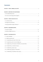
Page 3: ...4 ENGINEERING MODE 4 1 Engineering Mode 13 4 2 Engineering Mode Overview 14 CHAPTER 5 TROUBLESHOTING 5 1 Electrical Diagram 15 5 2 MCB Wiring Instructions 16 5 3 Troubleshooting No Power to the Consol...

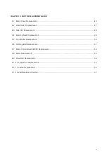
Page 4: ...l Replacement 28 6 4 Running Deck Replacement 29 6 5 Front Roller Replacement 30 6 6 Running Belt Replacement 31 6 7 Motor Control Board MCB Replacement 32 6 8 Motor Replacement 33 6 9 Drive Belt Repl...

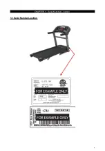
Page 5: ...CHAPTER 1 Serial Number Location 1 1 Serial Number Location 5...

Page 6: ...ath the treadmill or in any other area where it can become pinched or cut Check the tension and alignment of the running belt Make sure that the treadmill belt will not damage any other components on...

Page 7: ...r 5 seconds to suspend message for 5 miles Your treadmill came with a bottle of lubricant which can be used for two applications Turn off the treadmill with the on off switch then unplug the power cor...

Page 8: ...at the factory before it was shipped At times the belt can move off center during shipment Before operating the treadmill make sure the belt is centered and remains centered to maintain smooth operati...

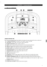
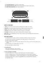
Page 9: ...ments 0 5 increments G SPEED KEYS used to adjust speed in small increments 0 1 mph increments H INCLINE QUICK KEYS used to reach desired incline more quickly I SPEED QUICK KEYS used to reach desired s...

Page 10: ...sure no objects are placed on the belt that will hinder the movement of the treadmill 2 Plug in the power cord and turn the treadmill ON The ON OFF switch is next to the power cord 3 Stand on the side...

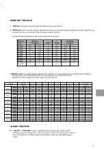
Page 11: ...ins Level 1 Incline 0 0 5 1 5 1 5 1 0 5 0 5 0 5 1 1 5 0 5 0 Speed 0 5 1 5 2 2 5 3 3 5 4 3 5 3 2 5 2 3 1 5 Level 2 Incline 0 0 5 1 5 1 5 1 0 5 1 0 5 1 1 5 0 5 0 Speed 0 5 1 9 2 5 3 3 5 4 4 5 4 3 5 3 2...

Page 12: ...of the console 1 To connect to the Bluetooth speakers open your Bluetooth settings turn on Bluetooth scan for new devices look for Horizon T202 and select connect AFG TABLET CONNECTED FITNESS SYSTEM...

Page 13: ...ne up speed down 1 3 TM without powered elevation motor speed up speed down 1 4 BK EP and ascent trainer without powered elevation motor resistance up resistance down 1 5 EP and ascent trainer with po...

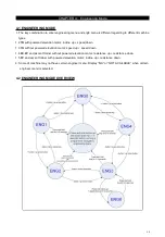
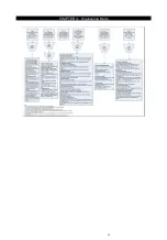
Page 14: ...CHAPTER 4 Engineering Mode 14...

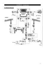
Page 15: ...CHAPTER 5 Troubleshooting 5 1 Electrical Diagram 15...

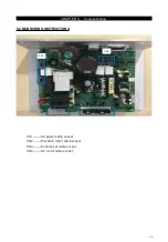
Page 16: ...CHAPTER 5 Troubleshooting 5 2 MCB WIRING INSTRUCTIONS Cn4 Cn1 Cn2 Cn3 CN1 AC power cable socket CN2 Elevation motor cable socket CN3 Console set cable socket CN4 AC motor cable socket 16...

Page 17: ...connection of the power wiring from the power receptacle to the MCB Use a multi meter to measure AC1 AC2 AC voltage shall be same as local s standard voltage 110V 240V If AC voltage value is standard...

Page 18: ...till shows safety key off 3 SOLUTION a Check if the safety key totally inserted in the console If no take off and insert again b Check if the safety key oxidized or not which will affect the conductio...

Page 19: ...ged the console is ok If not replace the PCB c Turn off the power switch and open the motor upper cover Remove the red black wires of motor from the MCB and use a multi meter to measure the resistance...

Page 20: ...G 1 Hardware Test Press the key ENTER first and then the key START Press the key INCLINE If can hear click from two relays at the MCB the MCB is ok Then check the connection of the elevation motor at...

Page 21: ...tensioned correctly Remove and clean the rollers if needed Replace the rollers or running belt as needed b This sound is likely a moving component Remove the motor cover and check the drive belt for a...

Page 22: ...eded Check to see if the air shock is making this noise lubricate or replace if needed f This sound is likely due to the air shock Lubricate or replace the air shock as needed g This sound is likely f...

Page 23: ...from the amp board to the console Replace the speaker or amp boards and wiring Replace the speakers If the speaker board amp board wiring and speakers do not solve the issue replace the console b Ther...

Page 24: ...g is bad Check the speaker wire connections Switch the speaker connections from one speaker to the other to see if sound switches sides If the sound does not switch sides replace the speaker board If...

Page 25: ...hest strap is damaged d The HR grips are damaged e Heart rate board damaged f The UCB is damaged 2 SOLUTION a Re center the chest strap below the user s pectoral muscle and check again b Replace the b...

Page 26: ...holding the motor cover to the frame Figures A B 2 The cover is secured to the frame with velcro so you will have to pull up with some force FIGURE A FIGURE B 3 Figure C shows the motor area with the...

Page 27: ...APTER 6 Part Replacement Guide 6 2 REAR ROLLER REPLACEMENT 1 Remove the rear end caps Figure A 2 Remove both roller adjustment screws Figure B FIGURE A FIGURE B 3 Remove the roller Figure C FIGURE C 2...

Page 28: ...ack of the treadmill Figures B FIGURE A FIGURE B 4 Reverse Steps 1 2 to install a new side rail NOTE After reinstalling the side rail make sure the rear end cap is on first before tightening the screw...

Page 29: ...ction 6 1 2 Remove the side rail as outlined in Section 6 3 3 Remove the end cap 4 Remove the running deck screws Figure A FIGURE A FIGURE B 5 Remove the running deck from the running belt Figure B 6...

Page 30: ...EMENT 1 Remove the motor cover as outlined in Section 6 1 2 Loosen both of the rear roller screws to remove tension from the running belt Figure A FIGURE A FIGURE B 3 Remove the drive belt from the fr...

Page 31: ...on 6 1 2 Remove the rear roller as outlined in Section 6 2 3 Remove the running deck as outlined in Section 6 4 4 Remove the front roller as outlined in Section 6 5 5 Remove the running belt Figures A...

Page 32: ...hine 2 Remove the motor cover as outlined in Section 6 1 3 Disconnect the wire connectors at the MCB 4 Remove the 2 screws holding each side of the MCB to the frame Figures A FIGURE A FIGURE B 5 Remov...

Page 33: ...3 Disconnect the motor cable ground wire from the grounding post 4 Disconnect the motor cable from the MCB 5 Remove the 4 screws holding the motor to the frame Figure A 6 Remove the drive belt FIGURE...

Page 34: ...cover as outlined in Section 6 1 3 Loosen the rear roller screws to relieve tension on the running belt 4 Remove the two 8 mm screws from front roller 5 Lift the roller and remove the old drive belt 6...

Page 35: ...on 6 1 3 Fold the treadmill 4 Remove the screws from the elevation rack Figure A Figure A Figure B 5 Disconnect the incline motor from the top mounting bracket Figure B 6 Reverse Steps 1 5 to install...

Page 36: ...t the power cord 2 Remove the 4 screws holding the console from the console mast Figure A FIGURE A FIGURE B 3 Remove the 5 screws holding the back of console Figure B 4 Disconnect the wires connection...

Page 37: ...eadmill and remove the power cord 2 Remove the console as outlined in Section 6 12 3 Loose the screws which fix the heart rate sensor Figure A FIGURE A 4 Disconnect the wires connections that go to th...

Reviews: