background image

01ETM

ISO 9001, ISO 14001 Certified

Printed in Japan

Marine Service Department

+81-3-3492-1305
+81-3-3779-1420
tmsc@jrc.co.jp

Telephone :
Facsimile :
e-mail :

Alphatron Marine Systems Pte Ltd

Telephone :
Facsimile :
e-mail :

+65 6863 0335
+65 6863 3305
service@alphatronmarinesystems.com

Singapore Branch

SEATTLE Branch

Telephone :
Facsimile :
e-mail :

+1-206-654-5644
+1-206-654-7030
marineservice@jrcamerica.com

CODE No.7ZPNA4466A

CODE No.7ZPNA4466A

JUL. 2015  Edition 3      JRC

JUL. 2015  Edition 3      JRC

Not use the asbestos 

For further information,contact:

URL

http://www.jrc.co.jp

Alphatron Marine B.V.

Telephone :
Facsimile :
e-mail :

+31 (0)10- 453 4000
+31 (0)10- 452 9214
service@alphatronmarine.com

Rotterdam (Head office)

URL

http://www.alphatronmarine.com

MARINE RADAR EQUIPMENT

MARINE RADAR EQUIPMENT

/ECDIS/CONNING

/ECDIS/CONNING

INSTALLATION MANUAL

INSTALLATION MANUAL

JMR-9230-S/S3

JMR-9230-S/S3

JMR-9225-7X3/9X3/6X/9X/6XH

JMR-9225-7X3/9X3/6X/9X/6XH

JMR-9210-6X/6XH

JMR-9210-6X/6XH

JMR-9272-S

JMR-9272-S

JMR-9282-S/SH

JMR-9282-S/SH

JMR-7230-S/S3

JMR-7230-S/S3

JMR-7225-7X3/9X3/6X/9X/6XH

JMR-7225-7X3/9X3/6X/9X/6XH

JMR-7210-6X/6XH

JMR-7210-6X/6XH

JMR-7272-S

JMR-7272-S

JMR-7282-S/SH

JMR-7282-S/SH

JAN-9201

JAN-9201

JAN-7201

JAN-7201

JAN-9202

JAN-9202

JAN-7202

JAN-7202

Summary of Contents for JAN-7201

Page 1: ...5 7X3 9X3 6X 9X 6XH JMR 9225 7X3 9X3 6X 9X 6XH JMR 9210 6X 6XH JMR 9210 6X 6XH JMR 9272 S JMR 9272 S JMR 9282 S SH JMR 9282 S SH JMR 7230 S S3 JMR 7230 S S3 JMR 7225 7X3 9X3 6X 9X 6XH JMR 7225 7X3 9X3 6X 9X 6XH JMR 7210 6X 6XH JMR 7210 6X 6XH JMR 7272 S JMR 7272 S JMR 7282 S SH JMR 7282 S SH JAN 9201 JAN 9201 JAN 7201 JAN 7201 JAN 9202 JAN 9202 JAN 7202 JAN 7202 ...

Page 2: ......

Page 3: ...nger charged Extra protection is ensured by wearing dry cotton gloves at this time Another important precaution to observe is to keep one hand in your pocket at a time instead of using both hands at the same time It is also important to select a secure footing to work on as the secondary effects of electrical shock hazards can be more serious In the event of electrical shocks disinfect the burnt s...

Page 4: ... ask someone to call doctor 4 Lay the patient on the back loosening the necktie clothes belts and so on 5 a Feel the patient s pulse b Check the heartbeat by bringing your ear close to the patient s heart c Check for respiration by bringing your face or the back of your hand to the patient s face d Check the size of patient s pupils 6 Opening the patient s mouth remove artificial teeth cigarettes ...

Page 5: ...take a deep breath and blow into the nostril through the pipe with the other nostril and the mouth completely closed 6 The patient may stand up abruptly upon recovering consciousness Keep the patient lying calmly giving him or her coffee tea or any other hot drink but not alcoholic drink to keep him or her warm Mouth to mouth artificial respiration with the patient s head lifted 1 1 Lift the back ...

Page 6: ...ss the patient s body until it is depressed about 2 cm Repeat this about 50 times a minute Cardiac massage 2 If only one first aider is available perform a cardiac massage about 15 times and then give mouth to mouth artificial respiration 2 times Repeat this sequence If two first aiders are available while one person performs a cardiac massage 15 times the other should give mouth to mouth artifici...

Page 7: ...has an intraoral injury you are hesitant about giving mouth to mouth resuscitation or preparing the mouthpiece for rescue breathing takes too long omit rescue breathing and proceed to the next step Open the airway Check for breathing Arrival of an AED Turn on the power Use the AED by following its voice prompts Fitting of the electrode pads etc Automatic electrocardiogram analysis Do not touch the...

Page 8: ...eatment 4 If not responding a Ask for help loudly Ask somebody to make an emergency 119 call and bring an AED Somebody has collapsed Please help Please call 119 Please bring an AED If there is nobody to help call 119 yourself 5 Open the airway a Touch the forehead with one hand Lift the chin with the two fingers of the middle finger and forefinger of the other hand and push down on the forehead as...

Page 9: ... the mouthpiece for rescue breathing takes too long omit rescue breathing and perform chest compressions c When performing rescue breathing it is recommended to use a mouthpiece for rescue breathing and other protective devices to prevent infections d While maintaining an open airway pinch the person s nose shut with your thumb and forefinger of the hand used to push down the forehead e Open your ...

Page 10: ...scitation CPR a When the injured or ill person has been handed over to the emergency services b When the injured or ill person has started moaning or breathing normally lay him her on his her side in a recovery position and wait for the arrival of emergency services 10 Arrival and preparation of an AED a Place the AED at an easy to use position If there are multiple first aiders continue CPR until...

Page 11: ...els you may need to push a button to analyze the heart rhythm 13 Electric shock defibrillation a If the AED determines that electric shock is needed the voice prompt saying Shock is needed is issued and charging starts automatically b When charging is completed the voice prompt saying Push the shock button is issued and the shock button flashes c The first aider must get away from the injured or i...

Page 12: ... When the injured or ill person has been handed over to the emergency services b When the injured or ill person has started moaning or breathing normally lay him her on his her side in a recovery position and wait for the arrival of emergency services ...

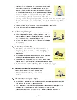
Page 13: ... INS Integrated Navigation System For the best operation read the instruction manual thoroughly before use Keep this manual in a convenient place for future reference Make use of this manual when experiencing operation difficulties The LCD of this equipment uses thin film transistors TFT If some pixels on the screen are not clear the color is different or the screen is brighter than usual it is no...

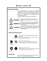
Page 14: ...nt are not operated correctly CAUTION This indication is shown where any person is supposed to be injured or any property damage is supposed to occur if this indication is neglected and these equipment are not operated correctly Examples of Pictorial Indication Electric Shock The mark represents CAUTION including DANGER and WARNING Detailed contents of CAUTION Electric Shock in the example on the ...

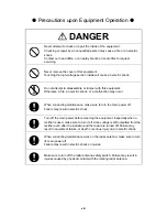
Page 15: ...occur When conducting maintenance make sure to turn the main power off Failure may result in electric shock Turn off the main power before cleaning the equipment Especially when a rectifier is used make sure to turn it off since voltage is still outputted from the rectifier even after the indicator and the radar are turned off Failure may result in equipment failure or death or serious injury due ...

Page 16: ...lose range can result in injury especially damage to eyes Microwave radiation level of the radar antenna System 50 W m2 20 W m2 2 5 W m2 NKE 2103 n a 26 cm 123 cm NKE 1125 1129 2254 5 cm 81 cm 162 cm NKE 1130 1139 11 cm 76 cm 181 cm NKE 2632 1 38cm 3 1cm 209 76cm NKE 1632 1 45cm 3 25cm 128 37cm Make sure to install the radar antenna at a place higher than human height Direct exposure to electromag...

Page 17: ... image becomes unstable by accessing the USB device not anticipated and it causes the breakdown Do not place a glass or cup containing water etc or a small metal object on this equipment If water or such object gets inside a fire an electric shock or a malfunction may occur In case water or a metal object gets inside the equipment turn off the power immediately unplug the power supply cable from a...

Page 18: ...ning water for more than 15 minutes If you find any skin problem afterwards consult a doctor immediately If the liquid gets in your eye wash it off immediately under running water for more than 15 minutes and then consult a doctor as soon as possible Before starting automatic sailing be sure to check the safety of the route and the safety when crossing safety contour Otherwise accidents may result...

Page 19: ...he sea surface at close range Detection of not only echoes from waves but also targets such as other ships or dangerous objects will become inhibited When using the AUTO SEA function make sure to choose the most appropriate image noise suppression level When using the AUTO RAIN function never set the suppression level too high Detection of not only echoes from the rain or snow but also targets suc...

Page 20: ...f the LCD display with a bare hand since high voltage temporarily remains in the circuit even after the main power is shut off Failure may result in electric shock Any adjustments must be made by specialized service personnel Incorrect settings may result in unstable operation and this may lead to accidents or equipment failure Do not make any adjustments during navigation Failure may result in ad...

Page 21: ... Do not place any object on the operation panel Avoid placing anything extremely hot in particular as this may deform the panel Do not apply any undue shock on the operation panel trackball and dials Otherwise a malfunction may result Please do not press and hold the power button of the operation unit It becomes the cause that prevents the normal start up Make sure that the main power is turned of...

Page 22: ...mpossible to observe using radar and this may lead to accidents In the case of turning on the power under the condition of low temperature do pre heat less than 30 minutes Otherwise the equipment may not start normally The judgement of formal or informal about chart depends on the administration organization of the flag state About the officially of the chart please contact the administration orga...

Page 23: ...xxi The Mounting Point of the Warning Label NDC 1590 Central Control Unit CCU NBD 913 Power Supply Unit PSU Warning Label Warning Label ...

Page 24: ...xxii CWA 246 26inch Display Unit Mount Kit Warning Label ...

Page 25: ...xxiii CWA 245 19inch Display Unit Mount Kit Warning Label ...

Page 26: ...xxiv NQE 3141 4A 8A Inter Switch Unit ISW NQE 3167 Power Control Unit NKE 1129 7 9 Radar Antenna NKE 1125 6 9 Radar Antenna Warning Label Warning Label Warning Label ...

Page 27: ...xxv Warning Label Warning Label NKE 1139 1130 Radar Antenna NTG 3230 3225 Transmitter Receiver ...

Page 28: ...xxvi Warning Label NKE 1632 Radar Antenna Warning Label NKE 2632 2632 H Radar Antenna ...

Page 29: ...xxvii EQUIPMENT APPEARANCE NKE 1139 Radar Antenna 12 feet NKE 1130 Radar Antenna 12 feet NKE 1632 Radar Antenna 12 feet NKE 2632 2632 H Radar Antenna 8 feet ...

Page 30: ...xxviii NTG 3230 Transmitter Receiver 30 kW ...

Page 31: ...xxix NKE 1129 7 Radar Antenna 7 feet NKE 1129 9 Radar Antenna 9 feet NKE 1125 6 Radar Antenna 6 feet NKE 1125 9 Radar Antenna 9 feet ...

Page 32: ...xxx NKE 2254 6HS Radar Antenna 6 feet NKE 2103 2103 6HS Radar Antenna 6 feet NTG 3225 Transmitter Receiver 25 kW ...

Page 33: ...xxxi CWA 245 Display Unit Mount Kit CWA 246 Display Unit Mount Kit ...

Page 34: ...xxxii NCE 5605 Trackball Operation Unit TOPU NCE 5625 Keyboard Operation Unit KOPU NDC 1590 Central Control Unit CCU NBD 913 Power Supply Unit PSU ...

Page 35: ...xxxiii NWZ 207 Monitor Unit 19inch NWZ 208 Monitor Unit 26inch NQE 3167 Power Control Unit Option ...

Page 36: ...xxxiv NQE 3141 4A Interswitch Unit ISW Option NQE 3141 8A Power Control Unit Option NQE 1143 Junction Box JB Option ...

Page 37: ... AZImuth stabilization mode Base CD Chart CD containing a complete chart data BCR BCT Bow Crossing Range Bow Crossing Time CCU Central Control Unit Cell Permit A file containing an encryption key for S 63 chart Supplied by UKHO PRIMAR STAVANGER and Hydrographic and Oceanographic Department of Japan Coast Guard Chart Maintenance Software to manage the charts Imports and updates the charts C MAP Ed ...

Page 38: ... the current speed on the horizontal axis of the 2 axis log is displayed EBL Electronic Bearing Line ECDIS Electronic Chart Display and Information System ENC Electronic Navigation Chart Meaning S 57 and S 63 ETA Estimated Time of Arrival ETD Estimated Time of Departure ENH Enhance F ETA Final Estimated Time of Arrival Extimated time of arrival to the last WPT GC Great Circle GPS Global Positionin...

Page 39: ... Maritime Mobile Service Identity MOB Man Over Board MON Performance MOnitor MP Medium Pulse NM Nautical Mile 1 nm 1852 m N up The north is always pointed to the top center of the radar display North up P0N Unmodulated pulse which is a type of transmission radio wave While it is a type of radio wave usually used by radars equipped with magnetrons radio waves with a short pulse length are used also...

Page 40: ...for Digital Hydrographic Data S 63 IHO Data Protection Scheme SA Certificate file An electronic file certifying the supplier of S 63 chart Required for import update of S 63 chart SENC System Electronic Navigational Chart SOG Speed Over the Ground SART Search And Rescue Transponder SET The current direction for manual correction or the current speed on the horizontal axis of the 2 axis log is disp...

Page 41: ...S 63 charts UTC Universal Time Coordinated VRM Variable Range Marker VDR Voyage Data Recorder WOL Wheel Over Line WOP Wheel Over Point WPT Waypoint WPT WPT The division of the leg specified by two points Displays data between two consecutive waypoints XTD Cross Track Distance XTL Cross Track Limit Activated target A target representing the automatic or manual activation of a sleeping AIS target fo...

Page 42: ...onsisting of semiconductor elements used for solid state radars It employs a high frequency high power FET Primary Main positioning sensor Pulse compression Correlation processing performed when a transmitted chirp signal is received by a solid state radar after reflecting off the target This processing gain enables the radar to have necessary detection capability even when a transmission power is...

Page 43: ...ation of depth SSR Solid State Radar Radar that uses semiconductor elements instead of magnetron which requires periodic replacement It is built with a system that ensures necessary detection capability even when a transmission output is low by using chirp signals with a long pulse length upon transmission and performing pulse compression upon reception Update Chart Maintenance A procedure of refl...

Page 44: ... 2254 6HS type scanner unit 2 14 2 2 3 NKE 1125 type scanner unit 2 16 2 2 4 NKE 1129 type scanner unit 2 18 2 2 5 NKE 1130 type scanner unit 2 20 2 2 6 NKE 1139 type scanner unit 2 22 2 2 7 NKE 1632 type scanner unit 2 24 2 2 8 NKE 2632 type scanner unit 2 26 2 3 Installation of Transmitter Receiver 2 28 2 3 1 NTG 3225 type transmitter receiver unit 2 28 2 3 2 NTG 3230 type transmitter receiver u...

Page 45: ...play Unit Mount Kit 3 15 3 3 12 Outline Drawings of CWB 1595 26inch Desktop Frame 3 16 3 3 13 Outline Drawings of CWB 1594 19inch Desktop Frame 3 17 3 3 14 Outline Drawings of CWB 1596 OPU Desktop Frame 3 18 3 3 15 Precautions for transporting and storing the display unit 3 19 3 3 16 Detaching the front frame of the Display unit mount kit 3 21 3 4 Installation of Standard Equipment 3 29 3 4 1 Inst...

Page 46: ...ction with Analog Sensors 3 124 3 7 9 Backup of sensor signal 3 127 3 8 Connection with ECDIS 3 130 3 8 1 Radar Overlay 3 130 3 8 2 Target Tracking 3 131 3 9 Connection with RADAR 3 132 3 9 1 Radar Overlay 3 132 3 9 2 Target Tracking 3 133 3 10 Connection with BNWAS 3 134 3 11 Ground Connection 3 135 3 11 1 Shield for Equipment 3 135 3 11 2 Cables for Equipment 3 135 3 11 3 Mounting Location 3 135...

Page 47: ... 73 4 19 Setting AIS RADAR ECDIS 4 80 4 20 Setting Display Size ALL 4 81 4 21 Tune Adjustment RADAR 4 83 4 22 Bearing Adjustment RADAR ECDIS 4 84 4 23 Range Adjustment RADAR ECDIS 4 85 4 24 Master Slave Radar Operation Mode RADAR ECDIS 4 86 4 25 Setting an Antenna Height RADAR ECDIS 4 87 4 26 Tune Peak Adjustment RADAR 4 88 4 27 Setting a Tune Indicator tuning indicator level RADAR 4 89 4 28 Setti...

Page 48: ...2 3 End processing of 2695110056 cable 5 15 5 2 4 End processing of each cable core 5 15 5 2 5 Connection to display unit 5 15 5 2 6 Outline Drawing of NQE 3167 Power Control Unit 5 16 5 2 7 Inter board connection diagram of power control unit 5 18 5 3 Connection of VDR 5 26 5 3 1 Connection with LAN IEC61162 450 5 26 5 3 2 Connection with Analog RGB 5 26 5 4 Printer 5 28 5 4 1 Printer Composition...

Page 49: ... 6 1 18 Outline Drawings of CWB 1593 Large Tray 6 18 6 1 19 Outline Drawings of NDC 1590 Central Control Unit 6 19 6 1 20 Outline Drawings of NBD 913 Power Supply Unit 6 20 6 1 21 Outline Drawings of NQE 1143 Junction Box 6 21 6 1 22 Outline Drawings of NQA 2443 Sensor LAN Switch Unit 6 22 6 1 23 Outline Drawing of CWA 246 26inch Display Unit Mount Kit 6 23 6 1 24 Outline Drawings of CWA 245 19inc...

Page 50: ...2 28 JAN 7202 6 55 6 3 General System Diagram of Desktop Type 6 56 6 3 1 JMR 9210 6X 6 56 6 3 2 JMR 9210 6XH 6 57 6 3 3 JMR 9225 6X 6 58 6 3 4 JMR 9225 6XH 6 59 6 3 5 JMR 9225 9X 6 60 6 3 6 JMR 9225 7X3 6 61 6 3 7 JMR 9225 9X3 6 62 6 3 8 JMR 9230 S 6 63 6 3 9 JMR 9230 S3 6 64 6 3 10 JMR 9272 S 6 65 6 3 11 JMR 9282 S 6 66 6 3 12 JMR 9282 SH 6 67 6 3 13 JAN 9201 6 68 6 3 14 JAN 9202 6 69 6 3 15 JMR ...

Page 51: ... JMR 9230 S3 6 94 6 4 7 JMR 9272 S 6 96 6 4 8 JMR 9282 S SH 6 98 6 4 9 JAN 9201 6 100 6 4 10 JAN 9202 6 102 6 4 11 JMR 7210 6X 6XH 6 104 6 4 12 JMR 7225 6X 9X 6 106 6 4 13 JMR 7225 6XH 6 108 6 4 14 JMR 7225 7X3 9X3 6 110 6 4 15 JMR 7230 S 6 112 6 4 16 JMR 7230 S3 6 114 6 4 17 JMR 7272 S 6 116 6 4 18 JMR 7282 S SH 6 118 6 4 19 JAN 7201 6 120 6 4 20 JAN 7202 6 122 6 5 Interconnection Diagram of Desk...

Page 52: ...165 6 6 3 NTG 3230 6 166 6 6 4 NKE 1130 AC110V 6 167 6 6 5 NKE 1130 AC220V 6 168 6 6 6 NKE 1129 AC110V 6 169 6 6 7 NKE 1129 AC220V 6 170 6 6 8 NTG 3225 6 171 6 6 9 NKE 1125 AC110V 6 172 6 6 10 NKE 1125 AC220V 6 173 6 6 11 NKE 2254 6HS 6 174 6 6 12 NKE 2103 6 6HS 6 175 6 6 13 NKE 1632 6 176 6 6 14 NKE 2632 2632 H 6 177 6 7 External input output sentence format 6 178 6 7 1 Receivable signals 6 178 6...

Page 53: ...6 9 1 System Block Diagram 6 199 6 9 2 Mechanism 6 201 6 9 3 Sentences 6 207 6 10 Troubleshooting 6 213 ...

Page 54: ...is added as the option 2 Case where the TCS function is added as the option Any of the following task functions can be added to this equipment as the option enabling the equipment to be used as a multi function display Radar ECDIS Conning Display 1 1 1 Main functions of the RADAR mode Sensitivity adjustment sea clutter and rain snow clutter suppression Interference rejection Bearing and range meas...

Page 55: ... at destinations bearings ranges up to waypoints and planned arrival time Availability of two EBLs VRMs Writing of memos with alphabetic characters into the electronic chart Display of information such as the date time current position heading and ship s speed Selection of colors conforming to the IMO IHO suitable for the daytime nighttime dawn and evening Editing of route information Addition del...

Page 56: ...ipped with the Help function The built in HTML Help enables the search of operation methods in this equipment instead of the hard copy manual whenever required Visual highlight of target symbols Enables identification of the target that matches the condition such as the sailing direction ship s length and ship s type by highlighted display Wave analysis function option Analyzes and displays inform...

Page 57: ...ctly selected to enable users to find the required information effortlessly Sortable TT AIS list Provides a sortable TT AIS list for instance in the TCPA descending order to enable users to check the ship in the highest danger Dual PPI display Capable of monitoring of near range images and far range images concurrently with one radar JMR 9200 Series only Superimposed display of radar image chart a...

Page 58: ...arts ENC and C MAP and raster chart ARCS Realizes safer sailing through the safety contour line and crossing and approaching danger zone monitoring function Excluding ARCS Realizes high operability through high speed drawing and high speed processing Facilitates creation of user charts Applies a multi display screen that can display two charts concurrently ARCS and C MAP Ed 3 cannot be displayed c...

Page 59: ...rconnection CMD 1103 1 NCE 5625 1 Option NCE 5625 or CWB 1593 Operation Circuit B CCK 1059 1 Option Keyboard CCK 1061 1 KOPU Interconnection CMD 1106 1 CWB 1593 1 Option NCE 5625 or CWB 1593 QUINT PS 1AC 24DC 20 1 QUINT BAT 24DC 3 4AH 1 QUINT DC UPS 24DC 20 1 ME MAX NEF QUINT20 1 NQE 1143 1 Option Serial LAN Circuit CMH 2370 max 2 Option Analog Option Circuit CMJ 560 1 Option Gyro Interface Circui...

Page 60: ... 4ch NQE 3141 4A 1 Option 8ch NQE 3141 8A 1 Option NQE 3167 1 Option 32ch NCT 82 1 Option 64ch NCT 83 1 Option CGC 25 1 Option TCS Buzzer RGB Video Distribution Amplifier VAC 2001HB A 1 Option Monitor Extension Kit CFQ 5957 1 Option JMR 92XX JAN 92XX CWB 1621 JMR 72XX JAN 72XX CWB 1619 JMR 92XX JAN 92XX CWB 1620 Option JMR 72XX JAN 72XX CWB 1618 Option CD Cleaner 7ZZNA0426B 1 Packing 1 box NBD 913...

Page 61: ...tegory B C English 7ZPNA4462 1 Option JAN 7201 9201 ECDIS Additional Manual for Automatic Sailing TOKYO KEIKI Autopilot PR 6000 9000 TCS model Category B C English 7ZPNA4463 1 Option JAN 7201 9201 ECDIS Type Specific ECDIS Training Reference for TCS English 7ZPNA4464 1 Option JMR 7200 9200 Series JAN 7201 9201 JAN 7202 9202 Marine Radar Equipment ECDIS Conning Display Installation Manual English 7...

Page 62: ...25 6 JMR 9225 9X NKE 1125 9 JMR 9225 6XH NKE 2254 6HS Wide range AC input 24VDC For backup JMR 9210 6X NKE 2103 6 JMR 9210 6XH NKE 2103 6HS JAN 9201 ECDIS JAN 9202 Conning JMR 7230 S3 RADAR MFD NKE 1139 NTG 3230 19inch NWZ 207 100 115VAC 50 60Hz 1 220 240VAC 50 60Hz 1 Specify between the two when ordering 24VDC For backup JMR 7230 S NKE 1130 JMR 7272 S NKE 1632 JMR 7282 S NKE 2632 JMR 7282 SH NKE ...

Page 63: ...AC as the radar power source a step down transformer shall be used 4 The following are the each unit name on the one s plate Scanner Unit SCANNER UNIT Transmitter receiver unit TRANSMITTER RECEIVER UNIT Monitor Unit MONITOR UNIT Trackball operation unit TRACKBALL OPERATION UNIT Keyboard operation unit KEYBOARD OPERATION UNIT Central Control Unit CENTRAL CONTROL UNIT Power supply unit POWER SUPPLY ...

Page 64: ...o of Wire φ Color Remarks 1 AWG24 7 0 2T Black1 Coaxial J832 Center Conductor 1 VD Outer Conductor 2 VD 2 AWG24 7 0 2T Black2 Shield 3 TRG 4 TRG 3 AWG24 7 0 2T Green 7 BZ 4 AWG24 7 0 2T Yellow 9 MTR 5 AWG24 7 0 2T White 10 MTR 6 AWG22 17 0 16T Black 6 BP 7 AWG22 17 0 16T Orange 5 BP 8 AWG16 50 0 18T Blue 9 AWG16 50 0 18T Gray 10 AWG16 50 0 18T Purple 11 AWG16 50 0 18T Brow n 12 AWG16 50 0 18T Whit...

Page 65: ...tallation of Display Unit for more information CQD 2273 Radar Interface Circuit VD 1 VD 2 TRG 3 TRG 4 BP 5 BP 6 BZ 7 BZ 8 MTR 9 MTR 10 MTRG 11 N C 12 DC 13 DC 14 2 1 Black 1 Coaxial Black 2 Shield Orange Green Yellow White N C Twisted Pair Brack Sky Green White Red Orange Blue Gray Purple Brown Black N C N C Yellow Pink J832 TB840 ...

Page 66: ...Coaxial Cable Center Conductor 1 VD Outer Conductor 2 VD 2 0 5 19 0 18 Black 2 Coaxial Cable Center Conductor 3 TRG Outer Conductor 4 TRG 3 0 5 19 0 18 Black 3 Coaxial Cable Center Conductor 5 BP Outer Conductor 6 BP 4 0 5 19 0 18 Black 4 Coaxial Cable Center Conductor 7 BZ Outer Conductor 8 BZ 5 5 5 35 0 45 Yellow 1 U 6 5 5 35 0 45 Green 2 V 7 5 5 35 0 45 Brow n 8 0 3 12 0 18 White Tw isted pair ...

Page 67: ...hapter 3 Installation of Display Unit for more information CQD 2273 Radar Interface Circuit VD 1 VD 2 TRG 3 TRG 4 BP 5 BP 6 BZ 7 BZ 8 MTR 9 MTR 10 MTRG 11 N C 12 DC 13 DC 14 V 2 U 1 Yellow Green Black 1 Coaxial Black 2 Coaxial Black 3 Coaxial Black 4 Coaxial Yellow White Braid White N C Twisted Pair Red Blue TB838 J832 ...

Page 68: ...18 Yellow Shield Center Conductor 5 ISWO_BP Braid 6 ISWO_BP B3 0 5 19 0 18 Green Shield Center Conductor 7 ISWO_BZ Braid 8 ISWO_BZ B4 0 5 19 0 18 Red Shield Center Conductor 3 ISWI_TRG Braid 4 ISWI_TRG B5 0 5 19 0 18 Purple Shield Center Conductor 5 ISWI_BP Braid 6 ISWI_BP B6 0 5 19 0 18 Clear Shield Center Conductor 7 ISWI_BZ Braid 8 ISWI_BZ 0 3 Blue 9 ISWO_MTR 0 3 White 10 ISWO_MTR Braid 11 ISWO...

Page 69: ...2 Installation of Scanner Unit 2 1 Equipment Cable 2 6 Wiring to the Display Unit is shown below Please refer to the 3 Installation of Display Unit for more information ...

Page 70: ...sily executed Ensure a place to store the cable 1 CFQ 6912 Cut off the metal shell connector CFQ 6912 Cutting position Remove about one meter of the outer skin and then process the double braided shield according to the procedures shown below CFQ 6912 Processing of braided shield Process each cable end according to the procedures shown below CFQ 6912 End processing of each wire ...

Page 71: ...g to the procedures shown below A slotted screwdriver is required How to insert the pin terminals into TB840 i Insert your flat head screwdriver into the upper slot of TB840 The cable slot lower slot will open ii Insert the crimp pin terminal into the cable slot lower slot iii Pull out your flat head screwdriver and the pin terminal will be fixed TB840 a Pin terminal a Flat head screwdriver Twist ...

Page 72: ... 2 9 2 2695110056 2695111153 Remove about one meter of the outer skin and then process the double braided shield according to the procedures shown below Processing of braided shield 269511056 2695111153 End processing of each wire 269511056 2695111153 ...

Page 73: ...ow 1 Use an attached lever or a flat head screw driver to press the control so as to open the cable inlet 2 Strip 8 to 9 mm of insulation off wire Check the strip length and then insert the wire until the end comes in contact 3 Release the tool from the terminal block and tighten the cable 4 After the cable has been connected gently tug at the cable to ensure that it is securely fastened Terminal ...

Page 74: ...ires of 2695110056 to the Junction Box the Faston terminals are required 1 Insert the Green or Yellow wire into the Faston terminal 2 Crimp the wire 3 Remove the clear cover of TB838 on CQD 2273 Radar Interface Circuit 4 Connect the Green or Yellow wires with Faston terminal to TB838 surely 5 Return the clear cover surely ...

Page 75: ...2 Installation of Scanner Unit 2 2 Installation for the specified scanner model 2 12 2 2 Installation for the specified scanner model 2 2 1 NKE 2103 type scanner unit ...

Page 76: ...2 Installation of Scanner Unit 2 2 Installation for the specified scanner model 2 13 ...

Page 77: ...2 Installation of Scanner Unit 2 2 Installation for the specified scanner model 2 14 2 2 2 NKE 2254 6HS type scanner unit ...

Page 78: ...2 Installation of Scanner Unit 2 2 Installation for the specified scanner model 2 15 ...

Page 79: ...2 Installation of Scanner Unit 2 2 Installation for the specified scanner model 2 16 2 2 3 NKE 1125 type scanner unit ...

Page 80: ...2 Installation of Scanner Unit 2 2 Installation for the specified scanner model 2 17 ...

Page 81: ...2 Installation of Scanner Unit 2 2 Installation for the specified scanner model 2 18 2 2 4 NKE 1129 type scanner unit ...

Page 82: ...2 Installation of Scanner Unit 2 2 Installation for the specified scanner model 2 19 ...

Page 83: ...2 Installation of Scanner Unit 2 2 Installation for the specified scanner model 2 20 2 2 5 NKE 1130 type scanner unit ...

Page 84: ...2 Installation of Scanner Unit 2 2 Installation for the specified scanner model 2 21 ...

Page 85: ...2 Installation of Scanner Unit 2 2 Installation for the specified scanner model 2 22 2 2 6 NKE 1139 type scanner unit ...

Page 86: ...2 Installation of Scanner Unit 2 2 Installation for the specified scanner model 2 23 ...

Page 87: ...2 Installation of Scanner Unit 2 2 Installation for the specified scanner model 2 24 2 2 7 NKE 1632 type scanner unit ...

Page 88: ...2 Installation of Scanner Unit 2 2 Installation for the specified scanner model 2 25 ...

Page 89: ...2 Installation of Scanner Unit 2 2 Installation for the specified scanner model 2 26 2 2 8 NKE 2632 type scanner unit ...

Page 90: ...2 Installation of Scanner Unit 2 2 Installation for the specified scanner model 2 27 ...

Page 91: ...2 Installation of Scanner Unit 2 3 Installation of Transmitter Receiver 2 28 2 3 Installation of Transmitter Receiver 2 3 1 NTG 3225 type transmitter receiver unit ...

Page 92: ...2 Installation of Scanner Unit 2 3 Installation of Transmitter Receiver 2 29 ...

Page 93: ...2 Installation of Scanner Unit 2 3 Installation of Transmitter Receiver 2 30 2 3 2 NTG 3230 type transmitter receiver unit ...

Page 94: ...2 Installation of Scanner Unit 2 3 Installation of Transmitter Receiver 2 31 ...

Page 95: ...rect exposure to electromagnetic waves at close range will have adverse effects on the human body Direct exposure to electromagnetic waves at close range will have adverse effects on the human body When it is necessary to get close to the scanner for maintenance or inspection purposes make sure to turn the indicator power switch to OFF or STBY Direct exposure to electromagnetic waves at close rang...

Page 96: ... rope and radiator Use suitable rope in length so that the distance from the crane s hook to the hoisting eyebolts will be 2 5m or more Use the protector attached on the radiator in factory an additional protector should be not used Because excessive protector will cause damage to the radiator s radome After installation of the scanner remove the protector from the radiator If the lifting rope is ...

Page 97: ...n increases resulting in the possibility of damage to the scanner Furthermore if installation bolts become loose due to deterioration of rubber or resin the scanner may be damaged or fall from its mount 3 Installation and clamping method a Installation direction Installation should be done so that the cable gland is oriented toward the stern b Bolts nuts and tightening torque to be used Use stainl...

Page 98: ...measures To prevent corrosion due to the contacts between different metals such as the scanner chassis legs installation surface bolts nuts etc cover the bolt s head and nuts with sealant Fig 2 7 Use of washer and corrosion resistant measures Fig 2 7 Use of washer and corrosion resistant measures d Grounding and corrosion resistant measures Ground the scanner chassis and the installation surface h...

Page 99: ...e guides are hollow inside when mounting them by using electric wire bands try not to fasten the bands too tightly around the cables and wave guides If they are fastened too tightly the inside will become deformed or blocked which may cause the receiving sensitivity to decrease or the transmitter receiver to be damaged Fig 2 9 Coaxial cable Fig 2 10 Flexible wave guide Stabilize the coaxial cable ...

Page 100: ...s for X band If the distance from the connecting portion and the supporting member is longer than the above distance vibration may cause metal fatigue resulting in the occurrence of malfunction even if the connecting portion is not removed Fig 2 11 Position of S band supporting member Fig 2 12 Position of X band supporting member For the cable end processing refer to the procedure manual which com...

Reviews: