background image

INSTRUCTION

INSTRUCTION

MANUAL

MANUAL

JMA

JMA-3300Series

3300Series

MARINE  RADAR

MARINE  RADAR

EQUIPMENT

EQUIPMENT

ISO 9001, ISO 14001 Certified

JUL. 2017  Edition 5

CODE No.7ZPRD0787

Not use the asbestos 

For further information,contact:

URL Head office :  http://www.jrc.co.jp/eng/
Marine Service Department
  1-7-32 Tatsumi, Koto-ku, Tokyo 135-0053, Japan
           : tmsc@jrc.co.jp
           : +81-50-3786-9201

e-mail
One-call 

Summary of Contents for JMA-3300 Series

Page 1: ... EQUIPMENT EQUIPMENT ISO 9001 ISO 14001 Certified JUL 2017 Edition 5 CODE No 7ZPRD0787 Not use the asbestos For further information contact URL Head office http www jrc co jp eng Marine Service Department 1 7 32 Tatsumi Koto ku Tokyo 135 0053 Japan tmsc jrc co jp 81 50 3786 9201 e mail One call ...

Page 2: ......

Page 3: ...ng dry cotton gloves ensures you further to prevent such danger It is also a necessary caution to put one of your hands in the pocket and not to use your both hands at the same time It is also important to select a stable foothold always to prevent additional injuries once you were shocked by electricity If you were injured from electric shock disinfect the burn sufficiently and get it taken care ...

Page 4: ...sk someone to call a doctor 4 Lay the victim on this back and loosen his necktie clothes belt etc 5 a Examine the victim s pulse b Examine his heartbeat bringing your ear close to his heart c Examine his breathing bringing the back of your hand or your face close to his face d Check the size of the pupils of his eyes 6 Open the victim s mouth and take out artificial teeth cigarette or chewing gum ...

Page 5: ...ostrils and blow into it blocking the other nostril and his mouth completely 6 When the victim recovers consciousness he may try to stand up suddenly but let him lie calmly and serve him with a cup of hot coffee or tea and keep him warm and quiet Never give him alcoholic drinks z Method of mouth to mouth respiration by raising head Fig 1 Mouth to mouth respiration 1 Raise the victim s head Support...

Page 6: ...escuer Repeat cardiac massages about 15 times and blow into his mouth 2 times quickly and repeat this combination In case of two rescuers one person repeats cardiac massages 15 times while the other person blow into his mouth twice and they shall repeat this combination Perform the cardiac massage and mouth to mouth respiration 3 Examine his pupils and his pulse sometimes When the both have return...

Page 7: ...ain safe operation of marine ships This equipment consists of a scanner unit and a display unit as its main units z Before operating the equipment be sure to read this instruction manual carefully for correct operation z Maintain this instruction manual so that operators can refer to it at anytime Refer to this manual when any inconvenience or defect occurs ...

Page 8: ... not operated correctly CAUTION This indication is shown where any person is supposed to be injured or any property damage is supposed to occur if this indication is neglected and these equipments are not operated correctly Examples of Pictorial Indication Electric Shock The ڹ mark represents CAUTION including DANGER and WARNING Detailed contents of CAUTION Electric Shock in the example on the lef...

Page 9: ...off Failure to comply may result in electrocution Turn off the main power before cleaning the equipment Especially when a rectifier is used make sure to turn it off since voltage is still output from the rectifier even after the radar is turned off Failure to comply may result in equipment failure electric shock or serious injury When conducting maintenance work on the antenna make sure to turn it...

Page 10: ...below The microwave exposure at close range could result in injuries especially of the eyes 50W m2 10W m2 2 5W m2 NKE 2103 n a 26cm 123cm Make sure to install the antenna at a place higher than human height Direct exposure to electromagnetic waves at close range will have adverse effects on the human body Direct exposure to electromagnetic waves at close range will have adverse effects on the huma...

Page 11: ...ge noise suppression level When using the sea clutter suppression function never set the suppression level too high canceling out all image noises from the rain or snow at close range Detection of not only echoes from the rain or snow but also targets such as other ships or dangerous objects will become inhibited When using the sea clutter suppression function make sure to choose the most appropri...

Page 12: ... avoidance Making the final navigation decision based only on the alarm may cause accidents such as collisions When setting an automatic acquisition zone make sure to properly adjust gain sea surface reflection suppression level and rain snow reflection suppression level so that the optimal target images are always on the radar screen The automatic acquisition zone alarm will not be activated for ...

Page 13: ...person attempts to replace the LCD he she may drop it and become injured Do not directly touch the inverter circuit of the LCD display with a bare hand since high voltage temporarily remains in the circuit even after the main power is shut off Failure to comply may result in electrocution When cleaning the display screen do not wipe it too strongly with a dry cloth Also do not use gasoline or thin...

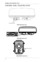
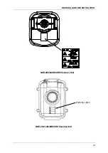
Page 14: ...WARNING LABEL MOUNTING POINT xii WARNING LABEL MOUNTING POINT NKE 2042 Scanner Unit NKE 2043 Scanner Unit Warning Label NKE 2062 HS Scanner Unit ...

Page 15: ...WARNING LABEL MOUNTING POINT xiii NKE 2063 A HS AHS Scanner Unit Warning Label NKE 2103 4 6 4HS 6HS Scanner Unit ...

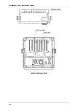
Page 16: ...WARNING LABEL MOUNTING POINT xiv NCD 2182 Display Unit ...

Page 17: ...WARNING LABEL MOUNTING POINT xv NBA 5111 Power Supply NBD 865 Rectifier unit ...

Page 18: ...EQUIPMENT APPEARANCE xvi EQUIPMENT APPEARANCE Scanner Unit Type NKE 2042 2 feet Scanner Unit Type NKE 2043 2 feet Scanner Unit Type NKE 2062 HS 3 9 feet Scanner Unit Type NKE 2063 A HS AHS 3 9 feet ...

Page 19: ...EQUIPMENT APPEARANCE xvii Scanner Unit Type NKE 2103 4 4HS 4 feet Scanner Unit Type NKE 2103 6 6HS 6 feet NCD 2182 Display Unit ...

Page 20: ... SYSTEM DIAGRAMS 1 15 Chapter 2 OPERATIONS 2 1 2 1 SCREEN DISPLAY 2 1 2 2 PANEL 2 2 2 3 POWER ON OFF 2 4 2 4 SENSITIVITY ADJUSTMENT 2 6 2 5 SEA CLUTTER SUPPRESSION 2 8 2 6 RAIN SNOW CLUTTER SUPPRESSION 2 11 2 7 SOFT KEY OPERATION 2 14 2 7 1 MEASURING TARGET BEARING EBL 2 22 2 7 2 MEASURING RANGE TO TARGET VRM 2 24 2 7 3 DISPLAYING PARALLEL CURSORS 2 26 2 7 4 SETTING VECTORS 2 29 2 7 5 DISPLAYING O...

Page 21: ...TX 2 74 2 8 BASIC MENU OPERATIONS 2 75 2 9 RADAR ECHO SETTINGS 2 79 2 9 1 SETTING RADAR INTERFERENCE REJECTION 2 79 2 9 2 SETTING FOR ENHANCING TARGETS 2 80 2 9 3 PROCESS 2 81 2 9 4 ZOOMING 2 82 2 9 5 VIDEO LATITUDE 2 82 2 9 6 VIDEO NOISE REJECTION 2 83 2 10 RADAR TRAIL LENGTH SETTING 2 84 2 11 MARKER SETTING 2 86 2 11 1 SETTING OPERATIONS FOR EBLS ELECTRONIC BEARING LINES 2 86 2 11 2 SETTING OPER...

Page 22: ...INT MARKS 2 135 2 17 2 SETTING MARK FUNCTIONS 2 136 2 17 3 SETTING LINE FUNCTIONS 2 140 2 17 4 DISPLAYING OWN SHIP S TRACK 2 144 2 17 5 FILE OPERATIONS 2 146 2 18 SETTING TIMED TX 2 153 Chapter 3 TRUE AND FALSE ECHOES ON DISPLAY 3 1 3 1 RADAR WAVE WITH THE HORIZON 3 1 3 2 REFLECTION FROM TARGET 3 3 3 3 SEA CLUTTER AND RAIN AND SNOW CLUTTER 3 4 3 3 1 SEA CLUTTER 3 4 3 3 2 RAIN AND SNOW CLUTTER 3 4 ...

Page 23: ...6 ERROR LOG 4 9 4 3 7 LINE MONITOR 4 11 4 3 8 SELF TEST 4 12 4 4 REPLACEMENT OF MAJOR PARTS 4 17 4 5 FAULT FINDING 4 19 4 5 1 LIST OF ALARMS AND OTHER INDICATIONS 4 19 4 5 2 FUSE CHECKING 4 28 4 6 TROUBLE SHOOTING 4 30 4 6 1 INCLUDED ACCESSORIES 4 30 4 6 2 SPECIAL PARTS 4 33 4 6 3 CIRCUIT BLOCK TO BE REPAIRED 4 34 Chapter 5 AFTER SALES SERVICE 5 1 5 1 KEEPING PERIOD OFMAINTENANCE PARTS 5 1 5 2 WHE...

Page 24: ...2 HS 7 5 7 2 4 NKE 2063 HS 6 7 7 7 2 5 NKE 2103 4 6 4HS 6HS 7 9 7 3 DISPLAY UNIT 7 11 7 3 1 INTEGRATED DISPLAY UNIT NCD 2182 7 11 7 3 2 OPERATION PANEL 7 13 7 3 3 AIS FUNCTION 7 13 7 3 4 TT FUNCTION 7 14 7 4 INPUT OUTPUT SIGNAL 7 15 7 4 1 INPUT ENABLE SIGNAL 7 15 7 4 2 OUTPUT ENABLE SIGNAL 7 15 7 5 STANDARD CONFIGURATION 7 16 APPENDIX INDEX ...

Page 25: ...Crossing Range and Bow Crossing Time C C up Course up Own ship s course is pointed to the top center of the radar display CCRP The Consistent Common Reference Point A location on own ship to which all horizontal measurements such as target range bearing relative course relative speed CPA or TCPA are referenced typically the conning position of the bridge Clutter Unwanted reflections on a radar scr...

Page 26: ...int to the bearing scale to indicate the heading of the ship H up Head up Own ship s heading line is always pointed to the top center of the radar display I IR Radar Interference Rejecter L Lost AIS target A target symbol representing the last valid position of an AIS target before the reception of its data was lost or its last dead reckoned position Lost tracked target One for which target inform...

Page 27: ...sity incident on the target Range Rings A set of concentric circles labeled by distance from CCRP Reference target A symbol indicating that the associated tracked stationary target is used as a speed reference for the ground stabilization Relative course The direction of motion of a target relative to own ship motion Relative speed The speed of a target relative to own ship s speed data Relative v...

Page 28: ...ship SP Short Pulse STAB Stabilization STW Speed Through Water The speed of the ship relative to the water surface T TCPA Time to Closest Point of Approach to own ship Test target Radar target of known characteristics used for test requirement TM True Motion A display across which own ship moves with its own true motion Trails Display Radar Trails Other Ships Trails True course The direction of mo...

Page 29: ...dinated The international standard of time kept by atomic clocks around the world V VRM Variable Range Marker An adjustable range ring used to measure the distance to a target W Waypoint A geographical location on a route indicating an event ...

Page 30: ...GLOSSARY xxviii ...

Page 31: ...nction of This System y Sensitivity adjustment y Sea clutter suppression y Rain snow clutter suppression y IR Interference rejection y Bearing and range measurement using a cursor fixed variable range markers and electronic bearing line y Own ship s track display y NAV line and marker displays y TM True Motion presentation y Self diagnostic y TT manual and automatic target acquisition automatic tr...

Page 32: ...ons are provided so that you can operate without this instruction manual Target Detection by Latest Signal Processing Technology The system employs a signal processing technology of DSP to eliminate undesired clutter thus improving the target detection TT and AIS functions as Standard Equipment High performance target tracking function which can automatically track targets up to 10 targets and AIS...

Page 33: ...nners and Transmitted Output Powers SCANNER TYPE TRANSMITTED OUTPUT POWER BAND RATE OF ROTATION JMA 3314 620mm Radome 4kW X 27 rpm JMA 3334 JMA 3316 3 9 FT SLOT ANTENNA 6kW 27 rpm JMA 3316HS 48 rpm JMA 3336 27 rpm JMA 3336HS 48 rpm JMA 3340 4 4 FT SLOT ANTENNA 10 kW 27 rpm JMA 3340 4HS 48 rpm JMA 3340 6 6 FT SLOT ANTENNA 27 rpm JMA 3340 6HS 48 rpm Reference 1 An optional rectifier NBA 5111 or NBD ...

Page 34: ... CODE 5ZFCA00051 1 for installation 3 for spares Fuse ST4 3 15AN1 4 Scanner NKE 2042 DC24V For the modulator F2 JRC CODE 5ZFCA00047 1 for installation 3 for spares Fuse ST4 6 3AN1 4 7ZXRD0012 Scanner NKE 2043 DC12V For the compound modulator F2 JRC CODE 5ZFCA00051 1 for installation 3 for spares Fuse ST4 3 15AN1 4 Scanner NKE 2043 DC24V For the compound modulator F2 JRC CODE 5ZFCA00047 1 for insta...

Page 35: ...spares Fuse ST4 3 15AN1 4 Scanner 1 6 6 9 For the compound modulator F2 JRC CODE 5ZFCA00047 1 for installation 3 for spares Fuse ST4 5AN1 4 Scanner NKE 2063 6 6 For the scanner motor F3 JRC CODE 5ZFCA00050 1 for installation 3 for spares Carbon brush 54531 01 2 Scanner NKE 2063 6 6 JRC CODE BRXP05247 2 for spares Fuse ST4 5AN1 4 7ZXRD0026 Scanner NKE 2103 4 4HS 6 6HS For the modulator F2 JRC CODE ...

Page 36: ...ODE REMARKS Rectifier NBA 5111 1 NBA 5111 For NKE 2042 NKE 2043 NKE 2062 HS NKE 2063 6 6 NKE 2103 4 4HS 6 6HS Rectifier NBD 865 1 NBD 865 For NKE 2042 NKE 2043 NKE 2062 NKE 2063 Equipment cable H CFQ 6912 5 H CFQ6912 10 CFQ 6912 15 H CFQ6912 20 H CFQ6912 30 CFQ6912 5 10 15 20 30 Cable connecting the scanner unit and the display unit Length 5 10 15 20 30 m Cable with connectors at both ends Cable c...

Page 37: ...Chapter 1 GENERAL AND EQUIPMENT COMPOSITION 1 4 EXTERIOR DRAWINGS 1 7 INSTRUCTION MANUAL 1 1 4 EXTERIOR DRAWINGS Fig 1 4 1 Exterior Drawing of Scanner Unit Type NKE 2042 ...

Page 38: ...Chapter 1 GENERAL AND EQUIPMENT COMPOSITION 1 4 EXTERIOR DRAWINGS 1 8 Fig 1 4 2 Exterior Drawing of Scanner Unit Type NKE 2043 ...

Page 39: ...Chapter 1 GENERAL AND EQUIPMENT COMPOSITION 1 4 EXTERIOR DRAWINGS 1 9 INSTRUCTION MANUAL 1 Fig 1 4 3 Exterior Drawing of Scanner Unit Type NKE 2062 HS ...

Page 40: ...Chapter 1 GENERAL AND EQUIPMENT COMPOSITION 1 4 EXTERIOR DRAWINGS 1 10 Fig 1 4 4 Exterior Drawing of Scanner Unit Type NKE 2063 A HS AHS ...

Page 41: ...Chapter 1 GENERAL AND EQUIPMENT COMPOSITION 1 4 EXTERIOR DRAWINGS 1 11 INSTRUCTION MANUAL 1 Fig 1 4 5 Exterior Drawing of Scanner Unit Type NKE 2103 4 4HS ...

Page 42: ...Chapter 1 GENERAL AND EQUIPMENT COMPOSITION 1 4 EXTERIOR DRAWINGS 1 12 Fig 1 4 6 Exterior Drawing of Scanner Unit Type NKE 2103 6 6HS ...

Page 43: ...Chapter 1 GENERAL AND EQUIPMENT COMPOSITION 1 4 EXTERIOR DRAWINGS 1 13 INSTRUCTION MANUAL 1 Fig 1 4 7 Exterior Drawing of Display Unit Type NCD 2182 1 2 ...

Page 44: ...Chapter 1 GENERAL AND EQUIPMENT COMPOSITION 1 4 EXTERIOR DRAWINGS 1 14 Fig 1 4 7 Exterior Drawing of Display Unit Type NCD 2182 2 2 ...

Page 45: ...S Fig 1 5 1 General System Diagram of Radar Reference Install the radar cable as far as from the cables of other radio equipment in order to prevent other radio equipment from interfering with the radar operations In particular do not install the antenna cable parallel to the cables of other radio equipment NKE 2063 A HS AHS ...

Page 46: ...Chapter 1 GENERAL AND EQUIPMENT COMPOSITION 1 5 GENERAL SYSTEM DIAGRAMS 1 16 ...

Page 47: ...Chapter 2 OPERATIONS 2 1 SCREEN DISPLAY 2 1 2 INSTRUCTION MANUAL Chapter 2 OPERATIONS 2 1 SCREEN DISPLAY ...

Page 48: ...N Press Performs the user key 3 function Hold down Switches the rain snow clutter suppression function between manual and automatic modes Turn Removes rain snow clutter շ RANGE Press Switches the range ո FUNC Press Switches function settings Hold down Opens the function setting menu չ BRILL Press Changes the display brilliance Hold down Opens the display color menu պ MULTI Press Opens the soft key...

Page 49: ...Key Operations Press Press a key then release the key before 2 seconds elapse Hold down Press a key and hold down the key for 2 seconds or more Press multiple keys Press multiple keys simultaneously Turn Turn a control in clockwise counterclockwise direction ...

Page 50: ...re setting it into the transmit state z If the preheating time is short the magnetron causes sparks resulting in its unstable oscillation Start transmission on a short pulse range and change the range to the longer pulse ranges in turn If the transmission is unstable in the meantime immediately place the system back into the standby state and maintain it in the standby state for 5 to 10 minutes be...

Page 51: ...by state if radar observation is restarted in a relatively short time Only pressing the TX PRF key starts observation Power Off 1 Press the STBY key and the TX PRF key simultaneously The system is turned off WARNING When conducting maintenance work make sure to turn off the power and unplug the power connector J1 of the display unit so that the power supply to the equipment is completely cut off S...

Page 52: ...same time if sensitivity is set too low detection of targets such as ships and dangerous objects may be hindered Therefore sensitivity must always be set to an optimal level Noise Adjustment 1 Turn the GAIN control Turn the GAIN control clockwise to increase sensitivity Turn the GAIN control counterclockwise to decrease sensitivity The sensitivity adjustment screen appears when turning the GAIN co...

Page 53: ...the targets and the background video As a result the targets become obscure on the radar display To observe densely crowded targets or short range targets turn the GAIN control counterclockwise to reduce the sensitivity so that the targets are easy to observe However be careful not to overlook important small targets Switching to Manual Automatic Mode 1 Hold down the GAIN control The sensitivity c...

Page 54: ...d When using the sea clutter suppression function make sure to choose the most appropriate image noise suppression level Manual Sea Clutter Suppression Function Adjust the sea clutter returns on the display unit to achieve better observation state 1 Turn the SEA control Turn the SEA control clockwise to suppress sea clutter returns Turn the SEA control counterclockwise to intensify sea clutter ret...

Page 55: ...radar display Automatic Sea Clutter Suppression Function Sea clutter suppression can be performed in accordance with the level of sea clutter Use this automatic mode when sea clutter returns vary in direction 1 Hold down the SEA control Automatic function is selected Even when the automatic function is selected you can manually perform fine adjustments by turning the SEA control The sea clutter su...

Page 56: ...unction is canceled The mode is indicated as shown below Reference When the automatic mode is selected for the sea clutter suppression function the rain snow clutter suppression function is switched to the manual mode The sea clutter suppression function Auto and the rain snow clutter suppression function Auto cannot be selected at the same time ...

Page 57: ...ing the sea clutter suppression function make sure to choose the most appropriate image noise suppression level Manual Rain Snow Clutter Suppression Function Adjust the rain snow clutter returns on the display unit to achieve better observation state 1 Turn the RAIN control Turn the RAIN control clockwise to suppress rain snow clutter returns Turn the RAIN control counterclockwise to intensify rai...

Page 58: ... to 0 Automatic Rain Snow Clutter Suppression Function Rain snow clutter suppression can be performed in accordance with the level of rain snow clutter Use this automatic mode when rain snow clutter returns vary in direction 1 Hold down the RAIN control Automatic function is selected Even when the automatic function is selected you can manually perform fine adjustments by turning the RAIN control ...

Page 59: ...tic function is canceled The mode is indicated as shown below Reference When the automatic mode is selected for the rain snow clutter suppression function the sea clutter suppression function is switched to the manual mode The sea clutter suppression function Auto and the rain snow clutter suppression function Auto cannot be selected at the same time ...

Page 60: ...s press the MENU key to open the menu screen This section describes the operation with the soft keys and the MULTI control Keys for operation y Soft keys 1 2 3 and 4 y MULTI control y CLEAR key Soft Key Operations Example Opening Display Screen This section describes how to operate with the soft keys shown below y TUNE PRF y Display Screen y TM RM y Bearing Mode y Pulse Length y Off Center y Symbo...

Page 61: ...urn the MULTI control to select Display Screen on the soft key menu Reference When a certain time elapses without any key operation after selecting an item on the soft key menu the soft key menu and the soft key display automatically disappear Display Screen is color inverted Press the MULTI control ...

Page 62: ...ct Own Track TLL TX X ۂ W Reference When the item at the bottom of the soft key menu is color inverted the soft key menu does not scroll any more even if the control is turned clockwise Own Track is color inverted Event Mark is color inverted TLL TX is color inverted AIS Filter is color inverted ...

Page 63: ... counterclockwise To select VRM2 EBL1 X ۂ W Reference When the item at the top of the soft key menu is color inverted the soft key menu does not scroll any more even if the control is turned counterclockwise VRM2 is color inverted VRM1 is color inverted EBL1 is color inverted EBL2 is color inverted ...

Page 64: ...een changes to the layout set in the section 4 13 7 LOCATION CHANGE 1 Screen1 z Soft key 2 The screen changes to the layout set in the section 4 13 7 LOCATION CHANGE 2 Screen2 Screen 1 is color inverted Screen 2 is color inverted Press the soft key 1 Press the soft key 2 ...

Page 65: ...ĺ 77 HWDLO ĺ 6 HWDLO ĺ Own AIS INFO ĺ 02 1FO z Closing the soft key menu Press the CLEAR key to turn off the soft key menu and the soft key display z Soft keys 1 2 3 and 4 If any of the soft keys is pressed when the soft key menu is turned off the soft key menu and the soft key display which were displayed previously appear again Numerical INFO is color inverted Press the soft key 4 Press any of t...

Page 66: ...y EBL2 y VRM1 y VRM2 y Parallel Cursor y Vector Length y RADAR Trails y AIS y TT y Alarm1 y Alarm2 y Brilliance 1 Press a soft key 2 Turn the MULTI control to select Brilliance on the soft key menu The soft key menu disappears and Monitor BRILL of the soft key display is color inverted Brilliance is activated Select Brilliance and press the control Press the MULTI control ...

Page 67: ...d is activated Press the BRILL key to adjust at eight levels Also you can turn the MULTI control to change the level z Setting with the soft key menu To determine the setting of the soft key menu item press one of the followings y Multi control y CLEAR key The soft key menu item is determined then the soft key menu and the soft key display are turned off and the setting is finished Monitor BRILL i...

Page 68: ...URING TARGET BEARING EBL Measures bearing with EBLs Electronic Bearing Lines 1 Select EBL1 EBL2 on the soft key menu When EBL1 is selected the soft key menu is turned off and BRG Operation of the soft key display is color inverted EBL1 is activated When EBL2 is selected the soft key menu is turned off and BRG Operation of the soft key display is color inverted EBL2 is activated Select EBL1 and pre...

Page 69: ...y floating off to floating state Press the cursor keys to move the starting point of EBL1 EBL2 Press the ENT key at the starting point of EBL1 EBL2 you want to move The starting point of EBL1 EBL2 is determined Reference The floating position of the EBL s starting point can be fixed on the radar display or at specific latitude and longitude Floating function must be turned on to use floating For d...

Page 70: ...e ends Reference When EBL1 EBL2 is not selected on the soft key menu press the soft key 4 to activate the EBL function EBL Bearing Display The bearing values of EBL1 and EBL2 displayed on the PPI are indicated at the radar display Even if EBL1 and EBL2 are not displayed the bearing values are displayed 2 7 2 MEASURING RANGE TO TARGET VRM Measures the range with VRM Variable Range Marker 1 Select V...

Page 71: ...not displayed y The soft key menu and the soft key display disappears and VRM function is terminated Soft key 2 NM km sm Selects units of VRM1 VRM2 range Soft key 3 Not available Soft key 4 DIST Operation When VRM1 or VRM2 of the soft key menu is selected DIST Operation of the soft key display is color inverted Turn the MULTI control to operate VRM1 VRM2 Press the MULTI control the soft key 4 or t...

Page 72: ... appears on the EBL2 If the starting point of an EBL is offset the center of a VRM marker is positioned at the starting point of the EBL VRM2 EBL2 VRM1 EBL1 2 7 3 DISPLAYING PARALLEL CURSORS Displays parallel cursors 1 Select Parallel Cursor on the soft key menu The soft key menu disappears and BRG Operation of the soft key display is color inverted Parallel Cursor is activated Select Parallel Cur...

Page 73: ...rminated Soft key 2 Floating When pressing the soft key 2 Floating is color inverted The starting point of the currently operating parallel cursor can be switched from the center of the radar display floating off to floating state Press the cursor keys to move the starting point of Parallel Cursor Press the ENT key at the starting point of Parallel Cursor you want to move The starting point of Par...

Page 74: ...ove the soft key 4 Turn the MULTI control to change the direction of Parallel Cursor Press the soft key 4 to determine the bearing setting of Parallel Cursor for length setting Length setting can be operated Press the MULTI control or the CLEAR key when you want to set the bearing only Bearing is set and operation state ends When Interval is displayed above the soft key 4 Turn the MULTI control to...

Page 75: ...perate with the soft keys Soft key 1 True Relative Switches between true vector mode and relative vector mode Soft key 2 Not available Soft key 3 Not available Soft key 4 Vector Length When Vector Length of the soft key menu is selected Vector Length of the soft key display is color inverted Vector time can be set in minutes in the range 1 to 60 min Turn the MULTI control to set the vector length ...

Page 76: ...arget s predicted position can presented in the True vector or Relative vector mode In each mode a vector length can be freely changed for a time interval of 1 to 60 minutes Vector Modes z True Vector Mode In the true vector mode the direction of a target vector indicates the true course of the target and its vector length is proportional to its speed In this mode own ship s vector is displayed as...

Page 77: ...r is not displayed Relative vector CPA ring HL Therefore the TRUE REL mode shall optionally be used for the purpose of observation the TRUE vector mode for grasping the true aspect of a target and the REL vector mode for grasping a target s closest point of approach CPA Vector Length The vector length of a target is proportional to its speed and the vector time can be switched in a range of 1 to 6...

Page 78: ...ar trails are plotted with unwanted waves change to a higher level y To thin radar trails change to a higher level y If radar trails are plotted in snatches change to a lower level Soft key 2 Time Cont Off Time Cont On This function superimpose displays time radar trails and continuous radar trails When Time Cont Off is selected this superimpose display is disabled When Time Cont On is selected th...

Page 79: ...ode Soft key 4 Trails When RADAR Trails of the soft key menu is selected Trails of the soft key display is color inverted Turn the MULTI control to change the radar trail length Reference When RADAR Trails is not selected on the soft key menu press the soft key 4 to activate the RADAR Trails function Short Off 15sec 30sec 1min 2min 3min 4min 5min 6min 10min 15min All Middle Off 30sec 1min 2min 3mi...

Page 80: ...t keys Soft key 1 Numerical Data Retrieved Vessel DEST Ship Numerical Data The mode is set to AIS numerical data display selection mode Retrieved Vessel The mode is set to AIS retrieved vessel selection mode DEST Ship The mode is set to AIS destination ship selection mode Soft key 2 Setting Release AIS data display numerical display retrieved vessel and destination ship can be set released Soft ke...

Page 81: ... Vessel DEST Ship z Displaying AIS data Operation with the soft key menu 1 Press the cursor keys to select AIS then press the ENT key y When Numerical Data is displayed above the soft key 1 y When Retrieved Vessel is displayed above the soft key 1 y When DEST Ship is displayed above the soft key 1 The specified target data is displayed and the symbol is changed The target data will remain on the r...

Page 82: ...splay of AIS On the TT symbol Opens the TT soft key and the numerical display of TT Not on the AIS or TT symbol Opens the TT soft key it will be acquired z If operating with the ENT key when the AIS symbol overlaps the TT symbol the numerical display of AIS symbol takes priority Reference y After setting the AIS numerical display perform the same operations in ە Displaying AIS data Operation with ...

Page 83: ... Displaying AIS data 1 Turn the MULTI control to select AIS then press the soft key 3 Setting Release y When Numerical Data is displayed above the soft key 1 y When Retrieved Vessel is displayed above the soft key 1 y When DEST Ship is displayed above the soft key 1 The specified target data is displayed and the symbol is changed The target data will remain on the radar display until the target is...

Page 84: ... then press the soft key 3 Setting Release Numerical Data AIS retrieved vessel and AIS destination ship are canceled AIS Symbols This section describes types and definitions of AIS symbols Symbol Definition Remarks Activated AIS target This symbol shows the position of an AIS target on the PPI The shape is an isosceles triangle and its vertex shows the approximate heading direction If heading bear...

Page 85: ... to swap them or lose part of them Such swapping or less of targets may also occur if the picture of the target being tracked is affected by rain snow clutter returns or sea clutter returns or moves very close to land II Intensity of echoes and the target tracking function The intensity of echoes and the tracking function have a correlationship and thus the target will be lost if no echoes are det...

Page 86: ...n such as vector target numerical data and alarms may contain some errors Also targets that are not detected by the radar cannot be acquired or tracked Making the final navigation decision based only on the radar display may cause accidents such as collisions or running aground 1 Select TT on the soft key menu The soft key menu disappears and Target Select of the soft key display is color inverted...

Page 87: ...key 4 to activate the TT function Target acquisition This equipment has automatic acquisition and manual acquisition z Manual acquisition Operation with the soft key menu Note z Manual acquisition can be operated when Soft key 1 TT Acquisition are selected z If the range is switched the acquisitions of targets acquired before switching the range are released when those targets get out of the echo ...

Page 88: ... or TT symbol Opens the TT soft key it will be acquired z If operating with the ENT key when the AIS symbol overlaps the TT symbol the numerical display of AIS symbol takes priority 1 Press the cursor keys to select the target for acquisition with the cursor then press the ENT key An initial acquisition symbol appears and the TT soft key is displayed After one minute elapses the target tracking sy...

Page 89: ...ated when Soft key 1 TT Release are selected 1 Press the cursor keys to select the target for releasing with the cursor then press the ENT key The target s vectors and symbols disappear and only the radar video remains Target tracking data numerical display Note z The numerical display can be operated when Soft key 1 Numerical Data are selected z Displaying tracking target data Operation with the ...

Page 90: ...numerical display of AIS On the TT symbol Opens the TT soft key and the numerical display of TT Not on the AIS or TT symbol Opens the TT soft key it will be acquired z If operating with the ENT key when the AIS symbol overlaps the TT symbol the numerical display of AIS symbol takes priority 1 Press the cursor keys to select the target for numerical display with the cursor then press the ENT key Th...

Page 91: ...adar display until the target is lost and its vector disappears or until another target is designated When the target for the numerical display is set is displayed in the TT list disappears when the target is released Reference y If a target with the mark ۑ is designated only its true bearing and range will appear until its vector appears y Tracking target data is displayed when the soft key 4 is ...

Page 92: ...cknowledged to new target alarm Dangerous target This symbol is displayed when the tracking target becomes a dangerous target with CPA TCPA decision This is displayed with a circle of thick line basic color is red This blinks while this is not acknowledged Then it stops blinking when it is acknowledged When there are some dangerous targets targets which is not acknowledged blinks and targets which...

Page 93: ... AUTOMATIC ACQUISITION OPERATIONS With a fan shaped range made the radar alarm can give an alarm to ships that enter or depart from the range 1 Select Alarm1 Alarm2 on the soft key menu The soft key menu disappears and Make Zone of the soft key display is color inverted Alarm1 is activated The soft key menu disappears and Make Zone of the soft key display is color inverted Alarm2 is activated Alar...

Page 94: ... AZ1 AZ2 Displays the acquisition area Soft key 3 When Alarm1 is selected In Out When Alarm2 is selected In Out Sets the alarm issuing conditions for the radar alarm In An alarm is issued when ship enters Out An alarm is issued when ship departs Soft key 4 When Alarm1 is selected Make Zone When Alarm2 is selected Make Zone Make Zone Make Zone When Make Zone of the soft key menu is selected Target ...

Page 95: ... Soft key 1 When Alarm1 is selected On When Alarm2 is selected On Soft key 2 When Alarm1 is selected AZ1 When Alarm2 is selected AZ2 The acquisition area is activated An initial acquisition symbol appears for an acquired target After one minute elapses the target tracking symbol is displayed z Turning off the automatic acquisition 1 Perform the following settings Soft key 1 When Alarm1 is selected...

Page 96: ...lected Sector AZ1 When Alarm2 is selected Sector AZ2 The range setting is started for a fan shaped radar alarm acquisition area 2 Press the cursor keys to move the cursor to the first point setting of the start bearing and range then press the ENT key 3 Press the cursor keys to move the cursor to the second point setting of the end range then press the ENT key ...

Page 97: ... acquisition area is determined Reference After the fan shaped radar alarm acquisition area is determined the soft key menu and the soft key display disappears and Alarm1 function is terminated Creating a rectangle shaped radar alarm 1 Perform the following settings Soft key 2 When Alarm1 is selected Rectangle When Alarm2 is selected Rectangle The range setting is started for a rectangle shaped ra...

Page 98: ...rst point setting of the start latitude and longitude then press the ENT key 3 Press the cursor keys to move the cursor to the second point setting of the end latitude then press the ENT key 4 Press the cursor keys to move the cursor to the third point setting of the end latitude then press the ENT key ...

Page 99: ... 1 Select Brilliance on the soft key menu The soft key menu disappears and Monitor BRILL of the soft key display is color inverted Brilliance is activated 2 Operate with the soft keys Soft key 1 Day1 Day2 Day3 Dusk Night Display color is changed in accordance with the setting of Main Menu Display Color Each time the soft key 1 is pressed when Day1 is displayed above the soft key WKH VHWWLQJ FKDQJH...

Page 100: ...the soft key menu press the soft key 4 to activate the Brilliance function 2 7 10 ADJUSTING SCANNER There are automatic tuning mode AUTO and manual tuning mode MAN In the automatic tuning mode transmission and receiving frequencies are tuned and adjusted automatically In the manual tuning mode tuning is carried out using the MULTI control 1 Select TUNE PRF on the soft key menu The TUNE PRF soft ke...

Page 101: ...ally adjust tuning Tuning is adjusted when transmission is started the range is changed or pulse length is changed Soft key 3 PRF Fine Tuning When pressing the soft key 3 PRF Fine Tuning is color inverted The PRF fine tuning screen appears Fine tune the transmitting repetition frequency of the transmitter in the range 90 to 100 If radar s interference patterns are concentrically displayed incremen...

Page 102: ... with the menu Adjust Menu Display Screen Location Change Screen1 Soft key 2 Screen2 The screen changes to the layout set with the menu Adjust Menu Display Screen Location Change Screen2 Soft key 3 Not available Soft key 4 Numerical INFO TT Detail AIS Detail Own AIS INFO MOB INFO Each time you press the soft key 4 when Numerical INFO is set the soft key display toggles in the following order 1XPHU...

Page 103: ...e menu When Numerical INFO is displayed above the soft key 4 Numerical INFO which has been set in the menu Screen 1 is displayed If Screen2 has been set in the menu When Numerical INFO is displayed above the soft key 4 Numerical INFO which has been set in the menu Screen 2 is displayed Numerical INFO Numerical INFO ...

Page 104: ... When Numerical INFO is displayed above the soft key 4 press the soft key 4 to display TT Detail on the radar screen AIS Detail When TT Detail is displayed above the soft key 4 press the soft key 4 to display AIS Detail on the radar screen TT Detail AIS Detail ...

Page 105: ...Own AIS INFO When AIS Detail is displayed above the soft key 4 press the soft key 4 to display Own AIS INFO on the radar screen MOB INFO When Own AIS INFO is displayed above the soft key 4 press the soft key 4 to display MOB INFO on the radar screen Own AIS INFO MOB INFO ...

Page 106: ...p is always shown on the radar display The heading line is hidden while the TX PRF key is held down so the targets on the heading line can be easily observed 2 7 12 SWITCHING TO TRUE RELATIVE MOTION DISPLAY MODE Switches between true and relative motion display modes Reference The bearing signal input is required to display true motion 1 Select TM RM on the soft key menu The TM RM soft key display...

Page 107: ...n the radar screen moves depending upon its speed and course and the influence of the current Land and other fixed targets are fixed on the radar screen and only actually moving targets move on the radar screen When the true motion display mode is selected the own ship s position is set to 66 of the display radius in the opposite direction to its course allowing for the influence of the current Ow...

Page 108: ...C Up 1 Select Bearing Mode on the soft key menu The Bearing Mode soft key display appears 2 Operate with the soft keys Soft key 1 H Up Relative bearing mode Head Up is selected Soft key 2 N Up True bearing mode North Up is selected Soft key 3 C Up Course up bearing mode Course Up is selected Soft key 4 C Up Reset In Course up mode reset the course up display Bearing Mode is color inverted ...

Page 109: ...ative to the ship s heading line the operator can view the video in the same field of view as in operating the ship at sea This mode is suitable for watching over other ships Head up mode HL True Bearing Mode The video is displayed so that the zenith of the PPI 0 on range rings points to the due north Fixed targets do not flicker and are easily identified on the chart and the true bearing of a tar...

Page 110: ...ne varies by the same shift of own ship s course To change the course press the soft key 3 several times to select the Course up mode and set a new course Course up mode HL North 2 7 14 SELECTING TRANSMITTER PULSE LENGTH Switches the transmitter pulse length 1 Select Pulse Length on the soft key menu The Pulse Length soft key display appears 2 Operate with the soft keys Soft key 1 SP MP1 MP2 LP1 L...

Page 111: ...ere targets are densely crowded Rough sea state due to torrential rain or stormy weather z MP The normal transmitter pulse length is set Both range resolution and sensitivity are appropriately set Recommended condition for selection General navigation z LP The transmitter pulse length becomes longer and sensitivity improves Small targets are zoomed and are easy to observe When the sea state is bad...

Page 112: ... s position on the radar screen Soft key 2 Off Center1 Off Center2 Off Center3 Custom Load Position Off Center1 The own ship s position is moved to 66 position of the display radius Off Center2 Te own ship s position is moved to 44 position of the display radius Off Center3 The own ship s position is moved to 22 position of the display radius Custom The own ship s position can be moved to any posi...

Page 113: ...ol Display on the soft key menu The Symbol Display soft key display appears 2 Operate with the soft keys Soft key 1 TT Display TT Display Off TT Display The TT symbols are displayed TT Display Off The TT symbols are hidden However the dangerous targets are shown Soft key 2 AIS Display AIS Display Off AIS Display The AIS symbols are displayed AIS Display Off The AIS symbols are hidden Soft key 3 Ma...

Page 114: ... soft key display appears 2 Operate with the soft keys Soft key 1 MOB Setting Sets the MOB at the own ship s position Soft key 2 MOB Release The displayed MOB is cleared Soft key 3 Not available Soft key 4 Not available 2 7 18 MARKING Marks can be indicated at arbitrary positions on the screen A mark created on the screen holds the latitude and longitude Reference y Bearing signal input and latitu...

Page 115: ...ete Press to delete the marks of selected type color Hold down to delete all marks The confirmation dialog window is displayed Marks and event marks are not distinguished when deleting Soft key 4 Off Enter Erase Move You can use the ENT key to create delete move the marks Enter Press the ENT key to create a mark at the cursor position Erase Press the ENT key to delete a mark at the cursor position...

Page 116: ...rget is changed Soft key 3 Delete Press to delete the lines of selected type color Hold down to delete all lines The confirmation dialog window is displayed Soft key 4 Off Enter Erase Move Insert You can use the ENT key to create delete move the lines Enter Press the ENT key to create a line at the cursor position Erase Press the ENT key to delete a line at the cursor position Move Use the cursor ...

Page 117: ...The Own Track soft key display appears 2 Operate with the soft keys Soft key 1 㸫㸫㸫㸫 The line type of the own ship s track is changed Soft key 2 White Cyan Blue Green Yellow Pink Red The line color of the own ship s track is changed Soft key 3 3sec 5sec 10sec 30sec 1min 3min 5min 10min 30min 60min 1NM 3NM 5NM 10NM The storage interval of the own ship s track is changed A preset time interval or pre...

Page 118: ... key display appears 2 Operate with the soft keys Soft key 1 X Y The mark type of a target is changed For details of size setting see 2 17 2 SETTING MARK FUNCTIONS Soft key 2 White Cyan Blue Green Yellow Pink Red The mark color of a target is changed Soft key 3 Delete Press to delete the marks of selected type color Hold down to delete all marks The confirmation dialog window is displayed Marks an...

Page 119: ...ority explained in AIS Symbols of Section 2 7 6 AIS OPERATIONS Reference y Bearing signal input and latitude longitude data input are required to use AIS functions y This function is initially set to off To use this function set this to on by referring to ڦ Soft Key Menu Setting in 4 10 Control of the Installation Manual 1 Select AIS Filter on the soft key menu The AIS Filter soft key display appe...

Page 120: ...L TX Transmits the TLL sentence of the cursor position on the screen to inform the mark position 1 Select TLL TX on the soft key menu The TLL TX soft key display appears 2 Operate with the soft keys Soft key 1 Off TLL TX Off TLL sentence is not transmitted with the ENT key TLL TX TLL sentence of the cursor position is transmitted with the ENT key Soft key 2 Not available Soft key 3 Not available S...

Page 121: ...e MENU key This section describes the operation with the MENU key Keys for operation y MENU key y Cursor keys y MULTI control y CLEAR key z CLEAR key Press the CLEAR key to return to the upper level MENU Key Operations Example Opening IR 1 Press the MENU key Select one of the menu items with mark then press the ENT key or the cursor key right to display the submenu ...

Page 122: ...ress the cursor key down or turn the MULTI control clockwise to select RADAR Echo 3 Press the ENT key the cursor key right or the MULTI control RADAR Echo menu appears Current settings are displayed on the right pane of the menu RADAR Echo is color inverted ...

Page 123: ...4 Press the cursor key down or turn the MULTI control clockwise to select IR 5 Press the ENT key the cursor key right or the MULTI control IR menu appears Selectable items are displayed on the right pane of the menu IR is color inverted The current setting is color inverted ...

Page 124: ...ed item then press the ENT key or the MULTI control 7 The setting is determined and displayed z Closing the menu Repeatedly press the CLEAR key or the cursor key left to return to the upper level and then close the menu screen Select the desired item Setting is determined ...

Page 125: ...menu items Reference After the settings for radar signal processing are changed small targets may not be displayed or unwanted waves may not be suppressed Thus do not make a significant change in the settings 2 9 1 SETTING RADAR INTERFERENCE REJECTION Setting Radar Interference Rejection Use this function to eliminate interference waves from other radars 1 Open RADAR Echo IR IR menu appears Off In...

Page 126: ... particularly when resolution is required Level1 Select this mode in general Expands the radar echo area at 1 step for vertical direction and at 1 step for horizontal direction Level2 Select this mode to easily view the radar video Expands the radar echo area at 1 step for vertical direction and at 2 steps for horizontal direction Level3 Select this mode to detect small targets such as buoys Expan...

Page 127: ...p however the video may be blurred Use this in TM mode Reference The bearing data input is required for video processing 1 Open RADAR Echo Process Process menu appears Off Select this mode in general 3Scan COREL Select this mode when many rain snow clutter returns are detected 4Scan COREL Select this mode to highlight targets while suppressing sea clutter returns 5Scan COREL Select this mode to de...

Page 128: ...ATITUDE Video Latitude Select the dynamic range in which receiving signals are to be shown on the radar display 1 Open RADAR Echo Video Latitude Narrow Narrows the dynamic range at short range Normal Standard setting The dynamic range varies depending on the actual range Short range long range Wide1 Use this mode when rainy weather intensifies unwanted waves The dynamic range is about twice as wid...

Page 129: ...and displayed like analog signals Level1 Rejects the signals of definitely unwanted waves noise and clutter When detection of targets or unwanted waves is not definite the signals are displayed When detection of targets is definite the signals are displayed Level2 Rejects the signals of definitely unwanted waves noise and clutter When detection of targets or unwanted waves is not definite the sign...

Page 130: ...ations 1 Open Trails from the Main Menu Trails menu appears Maximum value of radar trail display time MAX Interval Select the maximum time for displaying radar trails 1 Open Trails MAX Interval Short Sets 15 minutes as the maximum time for radar trails display Middle Sets 15 minutes as the maximum time for radar trails display Long Sets 1 hour as the maximum time for radar trails display Super Lon...

Page 131: ...long radar trails are necessary for ocean navigation Middle is for specification between Short and Long Continuous trails are available with all the options Short Off 15sec 30sec 1min 2min 3min 4min 5min 6min 10min 15min All Middle Off 30sec 1min 2min 3min 4min 5min 6min 10min 15min 30min All Long Off 1min 2min 3min 4min 5min 6min 10min 15min 30min 1hr All Super Long Off 30min 1hr 2hr 3hr 4hr 5hr ...

Page 132: ...SETTING Sets operations for EBLs parallel cursors cursors and range rings Marker operations 1 Open Marker from the Main Menu Marker menu appears 2 11 1 SETTING OPERATIONS FOR EBLS ELECTRONIC BEARING LINES EBL operations 1 Open Marker EBL1 EBL2 EBL menu appears ...

Page 133: ...ing point of an EBL is moved to a position the starting point can be fixed at the latitude and longitude of that position When the function is set to Screen Fix the starting point of an EBL is fixed on the radar display The starting point is always indicated at the same position on the radar display even when the own ship has moved 1 Open EBL1 EBL2 Floating Floating menu appears Off Floating mode ...

Page 134: ... the EBL is fixed to the true bearing 020 even when the own ship turns While the function is set to Screen Fix the EBL is fixed on the radar display 1 Open EBL1 EBL2 Bearing Fix Bearing Fix menu appears Angle Fix EBL bearing is fixed to the preset value Screen Fix EBL bearing is fixed on the radar display 2 11 2 SETTING OPERATIONS FOR PARALLEL CURSORS Parallel cursors can be set Parallel Cursor op...

Page 135: ...se and latitude longitude data input is required for floating setting When this function is set to L L Fix and the starting point of a parallel cursor is moved to a position the starting point can be fixed at the latitude and longitude of that position When the function is set to Screen Fix the starting point of a parallel cursor is fixed on the radar display The starting point is always indicated...

Page 136: ...earing For N Up and C Up the cursors are displayed in true bearing irrespective of changes in the course of own ship For H Up the angle of the parallel cursors changes as the course of own ship changes Screen Fix Fixes the parallel cursor display to the radar display For H Up N Up and C Up the angle of the parallel cursors stays the same on the screen When own ship is engaged in TM motions the par...

Page 137: ... The parallel cursors are displayed in One Side mode Both Sides The parallel cursors are displayed in Both Sides mode Displaying individual parallel cursors Individual parallel cursors can be displayed hidden 1 Open Parallel Cursor Display For Individual Line Line1 Off The parallel cursor is not displayed On The parallel cursor is displayed The line nearest to the own ship is specified as Line1 ...

Page 138: ... Open Marker Cursor Cursor menu appears Cursor Length Sets the length of the cross cursor mark on the radar display 1 Open Cursor Cursor Length Short Cuts the cross cursor mark in length Long Makes the cross cursor mark twice as long as when Short is selected Cursor Pattern Selects the type of the cross cursor mark on the radar display 1 Open Cursor Cursor Pattern ...

Page 139: ...rsor 1 Open Cursor Distance Unit NM The distance unit is set to NM km The distance unit is set to km sm The distance unit is set to sm 2 11 4 SETTING RANGE RINGS Displays hides the range rings Setting the range rings 1 Open Marker Range Ring Off The range rings are not displayed On The range rings are displayed ...

Page 140: ...ING This function enables the setting of detail information about radar display Display Screen operations 1 Open Display Color from the Main Menu Display Color menu appears Setting each items Sets the display color of each item z Day1 1 Open Display Color Day1 Day1 menu appears ...

Page 141: ...n Day1 SoftKey SoftKey menu appears Off Day1 is not displayed for the Display Screen soft keys On Day1 is displayed for the Display Screen soft keys Keyboard Unit Brilliance Adjusts the brilliance of operation panel Keyboard Unit Brilliance menu appears Outer PPI Adjusts the background color outside the bearing scale 1 Open Day1 Outer PPI Outer PPI menu appears ...

Page 142: ...n Outer PPI Color Color menu appears z Display Brilliance 1 Open Outer PPI Brilliance Brilliance menu appears Inner PPI Adjusts the background color inside the bearing scale 1 Open Day1 Inner PPI Inner PPI menu appears z Display Color 1 Open Inner PPI Color Color menu appears ...

Page 143: ...ce 1 Open Inner PPI Brilliance Brilliance menu appears Characters Adjusts the colors of characters and bearing scales 1 Open Day1 Character Character menu appears z Display Color 1 Open Character Color Color menu appears z Display Brilliance 1 Open Character Brilliance Brilliance menu appears ...

Page 144: ...R SETTING 2 98 RADAR Echo Adjusts the colors of radar echoes 1 Open Day1 RADAR Echo RADAR Echo menu appears z Display Color 1 Open RADAR Echo Color Color menu appears z Display Brilliance 1 Open RADAR Echo Brilliance Brilliance menu appears ...

Page 145: ...NUAL RADAR Trails Time Adjusts the colors of radar trails time 1 Open Day1 RADAR Trails Time RADAR Trails Time menu appears z Display Color 1 Open RADAR Trails Time Color Color menu appears z Display Brilliance 1 Open RADAR Trails Time Brilliance Brilliance menu appears ...

Page 146: ... Trails All Adjusts the colors of radar trails continuous 1 Open Day1 RADAR Trails All RADAR Trails All menu appears z Display Color 1 Open RADAR Trails All Color Color menu appears z Display Brilliance 1 Open RADAR Trails All Brilliance Brilliance menu appears ...

Page 147: ...101 2 INSTRUCTION MANUAL Own Ship s Adjusts the colors of own ship barge 1 Open Day1 Own Ship s Own Ship s menu appears z Display Color 1 Open Own Ship s Color Color menu appears z Display Brilliance 1 Open Own Ship s Brilliance Brilliance menu appears ...

Page 148: ...arget TT AIS Adjusts the colors of TT tracked target AIS symbols 1 Open Day1 Target TT AIS Target TT AIS menu appears z Display Color 1 Open Target TT AIS Color Color menu appears z Display Brilliance 1 Open Target TT AIS Brilliance Brilliance menu appears ...

Page 149: ...ANUAL EBL VRM Parallel Adjusts the colors of EBL VRM Parallel lines 1 Open Day1 EBL VRM Parallel EBL VRM Parallel menu appears z Display Color 1 Open EBL VRM Parallel Color Color menu appears z Display Brilliance 1 Open EBL VRM Parallel Brilliance Brilliance menu appears ...

Page 150: ...R SETTING 2 104 Range Ring Adjusts the colors of range rings 1 Open Day1 Range Ring Range Ring menu appears z Display Color 1 Open Range Ring Color Color menu appears z Display Brilliance 1 Open Range Ring Brilliance Brilliance menu appears ...

Page 151: ...OR SETTING 2 105 2 INSTRUCTION MANUAL Cursor Adjusts the colors of cursors 1 Open Day1 Cursor Cursor menu appears z Display Color 1 Open Cursor Color Color menu appears z Display Brilliance 1 Open Cursor Brilliance Brilliance menu appears ...

Page 152: ... 2 106 AZ Alarm Zone Adjusts the colors of AZ Alarm Zone 1 Open Day1 AZ Alarm Zone AZ Alarm Zone menu appears z Display Color 1 Open AZ Alarm Zone Color Color menu appears z Display Brilliance 1 Open AZ Alarm Zone Brilliance Brilliance menu appears ...

Page 153: ...ontrol from the Main Menu Control menu appears 2 13 1 DISPLAYING TRUE RELATIVE MOTION Sets the bearing standards for the cursor TT AIS and MOB Reference Bearing signal and speed signal input are required to display true motion Setting Bearing 1 Open Control Bearing True Relative Bearing True Relative menu appears True True bearing mode is selected Relative Relative bearing mode is selected ...

Page 154: ...ns 1 Open Control User Key User Key menu appears Factory presetting Sets functions that can be performed with the user keys User key items Off No function is assigned to this user key VRM1 Unit The setting can be changed in VRM1 unit on the radar display VRM2 Unit The setting can be changed in VRM2 unit on the radar display Alarm Radar alarms can be set Display Display can be set Operate the same ...

Page 155: ...NUAL Using user keys Operates as user keys z Displaying the menu assigned to the user key1 Hold down the GAIN control z Displaying the menu assigned to the user key2 Hold down the SEA control z Displaying the menu assigned to the user key3 Hold down the RAIN control ...

Page 156: ...ust the sound volume as follows Buzzer operations 1 Open Control Buzzer Buzzer menu appears Setting volume Sets Key ACK volume Turn the MULTI control to adjust Key ACK volume Key ACK volume can be adjusted between 0 and 255 When 0 is set the volume is turned off Operate the same way for the other volume settings Output Buzzer operations 1 Open Control Output Buzzer Output Buzzer menu appears ...

Page 157: ...buzzer for CPA TCPA Off Sets the external buzzer to Off On Sets the external buzzer to On Operate the same way for the other external buzzer settings Reference For details of external buzzer connection refer to 3 10 CONNECTING CONTACT SIGNALS TO EXTERNAL BUZZERS EXTERNAL DEVICES in the INSTALLATION MANUAL ...

Page 158: ...ttings can be fine adjusted by operating the menu You can select one of 4 function modes The factory presetting is shown below Function1 Setting Standard Suitable for general monitoring Function2 Setting Coast Useful for observing short range videos Function3 Setting Deepsea Suitable for general ocean navigation Function4 Setting Fishnet Useful for small target 2 14 1 FUNCTION KEY OPERATIONS Funct...

Page 159: ... Setting menu appears when holding down the FUNC key Changing the setting z Temporarily changing the setting y When radar signal processing setting is changed by using the soft key or the menu operation while function 1 to 4 is called the change is temporarily reflected to the operating state y Since this method does not change the memory contents the new setting is deleted as soon as another func...

Page 160: ... 8 Video Latitude The dynamic range setting Narrow Normal Wide1 Wide2 9 Video Noise Rejection The setting of video level not displayed on the radar display Off Level1 Level2 Level3 10 Trails Interval The setting of display time of radar trails Off 15sec 30sec 1min 2min 3min 4min 5min 6min 10min 15min CONT 11 Trails Mode The setting of true relative mode of radar trails TM RM 12 Trails REF Level Th...

Page 161: ... following 12 modes are provided Standard Use this mode for general purpose This is suitable to monitor a relatively short range Coast Use this mode to monitor a relatively short range for example bays and coasts where many boats and ships are running Importance is attached to resolution Deepsea Use this mode to monitor a relatively long range for example the open sea Importance is attached to lon...

Page 162: ...nce in the open sea EU River Use this mode when adjusting the functions mainly suitable for rivers in Europe Use this mode to reduce sea clutter returns User1 General mode used when the nine modes above are not applicable User2 General mode used when the nine modes above are not applicable z IR Interference rejection Operate the same way for the interference rejection settings in the menu For deta...

Page 163: ...ter suppression function Off Disables the automatic clutter suppression function Select Off when rain snow clutter and sea clutter are not strong or when the ship is in a bay AUTO STC Automatically detects the strength of sea clutter and performs the most suitable sea clutter suppression processing Even when the strength of sea clutter varies depending on the wind direction AUTO STC performs the m...

Page 164: ...SPLAYING OTHER SHIP S TRACKS RADAR TRAILS z Trails Mode Operate the same way for the trail interval settings in the soft key menu For details of operations refer to 2 7 5 DISPLAYING OTHER SHIP S TRACKS RADAR TRAILS z Trails REF Level Operate the same way for the trail interval settings in the soft key menu For details of operations refer to 2 7 5 DISPLAYING OTHER SHIP S TRACKS RADAR TRAILS z Time ...

Page 165: ...signal processing mode 5m Set the antenna height under 5 m 5 10m Set the antenna height 5m to 10m 10 20m Set the antenna height 10 m to 20 m 20m Set the antenna height over 20 m z Save Present State Registers the currently used settings as function settings z Set Mode Default Sets the initial value of a selected function setting mode Select this item to change the current function mode to the init...

Page 166: ... This pattern consists of two closed loops in principle one of which is a collision with another mobile craft and the other is a loop of finding a right and safe way to reach a predeterminate destination Fig 2 15 1 shows the conceptual diagram of navigation pattern by MR E W Anderson The closed loop of collision avoidance is shown on the left side and the closed loop of finding a right course on t...

Page 167: ...To cope with these problems any effective measures are needed and some equipment to achieve collision avoidance requirements have been developed at rapid strides Basic Concept of Collision Avoidance There are two aspects in collision avoidance collision prediction and avoidance Collision prediction is to predict that two or more vessels will happen to occupy the same point at the same time while c...

Page 168: ...the act of prevention of collision at sea can be readily grasped If there is a risk of collision with other ship the operator can determine which rule to be applied and how to operate own ship Fig 2 15 3 Relative Vector and True Vector N T T T R T A T O Vo VR VT VO Own ship s speed T O Own ship s course VT Other ship s true speed T T Target ship s true course VR Target ship s relative speed T R Ta...

Page 169: ...perations 1 Open Target from the Main Menu Target menu appears Turning On Off the Function Turns on off tracking target and AIS function 1 Open Target Function On Off Function On Off menu appears z Turning on off the tracking target function 1 Open Function On Off TT TT menu appears Off Turns off the TT function On Turns on the TT function ...

Page 170: ...he AIS function Setting Collision Decision Criteria Set and check collision decision criteria before operating Input the CPA Limit value Turn the MULTI control to set the CPA Limit value The CPA Limit value can be set between 0 1 and 9 9 NM Input the TCPA Limit value Turn the MULTI control to set the TCPA Limit value The TCPA Limit value can be set between 1 and 99 min ...

Page 171: ...ce The CPA ring is not displayed when the true vector mode is selected See 2 7 4 SETTING VECTORS to change the settings 2 15 3 SETTING TARGET NUMBER DISPLAY A target ID number is a value displayed beside the target symbol or AIS symbol These numbers are assigned to targets in acquisition order The numbers 1 to 10 are automatically assigned Each target is identified by the assigned ID number until ...

Page 172: ...numbers of TT AIS are not displayed On Target numbers of TT AIS are displayed Reference An ID number is always displayed for only targets with which numeric data is displayed 2 15 4 SETTING TARGET NUMBER ALLOCATION The start number of target can be specified for the target symbol or AIS symbol Target Number Allocation operations 1 Open Target Target Number Allocation Target Number Allocation menu ...

Page 173: ...The start number of target can be adjusted between 0 and 90 AIS The start number of target can be adjusted between 0 and 50 Own Ship s The start number of target can be adjusted between 0 and 99 Cursor The start number of target can be adjusted between 0 and 99 Reference Set the target number of TT AIS not to overlap each other 2 15 5 SETTING AIS ALARM Sets the display of NMEA ALR sentence receive...

Page 174: ... to 20 30 The number of AIS display targets is set to 30 40 The number of AIS display targets is set to 40 50 The number of AIS display targets is set to 50 2 15 7 SETTING AIS DESTINATION SHIP DirecTrakTM AIS destination ship is the function to display the user specified ship as the destination If MMSI of AIS target is set the destination ship can be specified Setting AIS Destination Ship 1 Open T...

Page 175: ...rieved vessel can be specified Reference AIS retrieved vessel can be set up to 10 vessels AIS Retrieved vessel operations 1 Open Target AIS Retrieved Vessel AIS Retrieved Vessel menu appears MMSI Number Setting 1 Open AIS Retrieved Vessel MMSI Number Setting Retrieved Vessel info 1 Turn the MULTI control to set MMSI number MMSI number can be adjusted between 0 and 999999999 Operate the same way fo...

Page 176: ...fer to 2 7 22 SETTING AIS FILTER Setting AIS Filter 1 Open Target AIS Filter Turn the MULTI control to set the range for AIS filter The range can be set between 0 and 72 0 NM 2 15 10 FILE OPERATION The stored MMSI number setting of AIS retrieved vessel is output via USB File Operation 1 Open Target File Operation File Operation menu appears ...

Page 177: ... dialog box Overwrite appears Yes Saves via USB No Does not save via USB Note z After saving data to a USB memory move the data to a storage such as PC that can store the data with password to prevent data leakage When selecting Yes Processing appears on the radar screen After saving is finished the screen returns to Save menu When selecting No the screen returns to Save menu ...

Page 178: ...opening AIS Retrieved vessel the dialog box This function cannot be returned to the origin Are you sure appears Yes Loads via USB No Does not load via USB When selecting Yes Processing appears on the radar screen After saving is finished the screen returns to Load menu After saving is finished the screen returns to Load menu ...

Page 179: ...ars When opening AIS Retrieved vessel the dialog box This function cannot be returned to the origin Are you sure appears Yes Erases data via USB No Does not erase data via USB When selecting Yes Processing appears on the radar screen After saving is finished the screen returns to Erase menu When selecting No the screen returns to Erase menu ...

Page 180: ...TIONS RADAR Alarm operations 1 Open Main Menu RADAR Alarm RADAR Alarm menu appears Setting Detection Level 1 Open RADAR Alarm RADAR Alarm1 Level RADAR Alarm1 Level menu appears Select Level1 Level2 Level3 or Level4 Operate the same way for the settings of RADAR Alarm2 Level Note z Select Level1 Level2 Level3 or Level4 for alarm level When setting to lower level of detection the alarm operates for ...

Page 181: ...on equipment the waypoint mark appears on the radar display ۑ is indicated as the waypoint mark on the radar display Setting for Waypoint Display 1 Open Plot Waypoint Display Off The waypoint marks are not displayed On The waypoint marks are displayed Waypoint marks are displayed only when NMEA RMB BWC sentences are used to receive Waypoint information Reference To display Numerical INFO of waypoi...

Page 182: ...ark Size Small Small marks are used Large Large marks are used Display Mark Color Displays the marks with the specified color 1 Open Mark Display Mark Color When All is set to All The setting of All is prior to individual settings When All is set to Individual Individual settings are prior to the setting of All On Displays the marks with the specified color Off Does not display the marks with the ...

Page 183: ... 1 Open Mark Display Mark Type When All is set to All The setting of All is prior to individual settings When All is set to Individual Individual settings are prior to the setting of All On Displays the marks with the specified type Off Does not display the marks with the specified type Mark List Displays the mark list screen ...

Page 184: ...1 Add Creates marks Press the soft key 1 Add Add menu appears Use the cursor keys to input Type Color and LAT LON then press the Enter Use the cursor keys to select the Type Use the cursor keys to select the Color Use the cursor keys to select the LAT LON ...

Page 185: ...ark list Soft key 2 Delete Erases marks Turn the MULTI control to select a mark list Press the soft key 2 Erase to erase the mark Soft key 3 Edit Edits marks Turn the MULTI control to select a mark Press the soft key 3 Edit Use the cursor keys to edit Type Color and LAT LON then press the Enter ...

Page 186: ...Display Line Color Displays the lines with the specified color 1 Open Line Display Line Color When All is set to All The setting of All is prior to individual settings When All is set to Individual Individual settings are prior to the setting of All On Displays the lines with the specified color Off Does not display the lines with the specified color ...

Page 187: ... 1 Open Line Display Line Type When All is set to All The setting of All is prior to individual settings When All is set to Individual Individual settings are prior to the setting of All On Displays the lines with the specified type Off Does not display the lines with the specified type Line List Displays the line list screen ...

Page 188: ...1 Add Creates lines Press the soft key 1 Add Add menu appears Use the cursor keys to input Type Color and LAT LON then press the Enter Use the cursor keys to select the Type Use the cursor keys to select the Color Use the cursor keys to select the LAT LON ...

Page 189: ...y 2 Delete Erases lines Turn the MULTI control to select a line list Press the soft key 2 Erase to erase the mark Soft key 3 Edit Edits lines Turn the MULTI control to select a line Press the soft key 3 Edit Use the cursor keys to edit Type Color and LAT LON then press the Enter Soft key 4 Insert Inserts lines ...

Page 190: ...cannot be selected Press the soft key 4 Insert Use the cursor keys to edit Type Color and LAT LON then press the Enter Figure shows the state when line 2 is selected 2 17 4 DISPLAYING OWN SHIP S TRACK Sets the own ship s track display Own Track operations 1 Open Plot Own Track Own Track menu appears ...

Page 191: ...r to the setting of All On Displays the own tracks with the specified color Off Does not display the own tracks with the specified color Display Own Track Type Displays the own tracks with the specified type 1 Open Own Track Display Own Track Type Display Own Track Type menu appears When All is set to All The setting of All is prior to individual settings When All is set to Individual Individual s...

Page 192: ...Specifies the type of the own tracks to be cleared Clear Own Track Clears the own tracks according to the setting of Clear Own Track Color and Clear Own Track Type 2 17 5 FILE OPERATIONS Marks lines and own tracks stored in the equipment can be output via USB terminal File Operation operations 1 Open Plot File Operation File Operation menu appears Saving Marks Lines Own Tracks Marks lines and own ...

Page 193: ... After saving is finished the screen returns to Save menu When overwriting the dialog box Exist Same File Overwrite appears When selecting Yes Processing appears on the radar screen After saving is finished the screen returns to Erase menu When selecting No the screen returns to Erase menu Note z After saving data to a USB memory move the data to a storage such as PC that can store the data with p...

Page 194: ...ing is finished the screen returns to Save menu When overwriting the dialog box Exist Same File Overwrite appears When selecting Yes Processing appears on the radar screen After saving is finished the screen returns to Erase menu When selecting No the screen returns to Erase menu Note z After saving data to a USB memory move the data to a storage such as PC that can store the data with password to...

Page 195: ...Load Mark Line Mark Line menu appears Turn the MULTI control to select the file number When selecting the file the dialog box This function cannot be returned to the origin Are you sure appears Yes Loads data via USB No Does not load data via USB When selecting Yes Processing appears on the radar screen After saving is finished the screen returns to Erase menu When selecting No the screen returns ...

Page 196: ... the file number When selecting the file the dialog box This function cannot be returned to the origin Are you sure appears Yes Loads data via USB No Does not load data via USB When selecting Yes Processing appears on the radar screen After saving is finished the screen returns to Erase menu When selecting No the screen returns to Erase menu ...

Page 197: ...z Erasing Mark Line 1 Open Erase Mark Line Mark Line menu appears Turn the MULTI control to select the file number When selecting the file the dialog box This function cannot be returned to the origin Are you sure appears When selecting Yes Processing appears on the radar screen After saving is finished the screen returns to Erase menu When selecting No the screen returns to Erase menu ...

Page 198: ...n the MULTI control to set the file number When selecting the file the dialog box This function cannot be returned to the origin Are you sure appears When selecting Yes Processing appears on the radar screen After saving is finished the screen returns to Erase menu When selecting No the screen returns to Erase menu ...

Page 199: ...dly changed between TX and standby state The timed TX function can set TX time and standby time as desired Timed TX operations 1 Open Main Menu Timed TX Timed TX menu appears Turning on off Timed TX Function Turns on off the timed TX function Off Sets the timed TX function to Off On Sets the timed TX function to On Reference The timed TX function can be turned off only in TX state It cannot be tur...

Page 200: ... the number of antenna rotation Turn the MULTI control to set the TX time TX time can be adjusted between 0 and 99Scan Setting Standby Time Sets the time for standby state Turn the MULTI control to set the Standby Time The standby time can be adjusted between 0 and 99min ...

Page 201: ...rt to measure own ship s position in the coastal waters relative to the bearings and ranges of the shore or islands using a chart and to monitor the position and movement of a heavy rain if it appears on the radar display Various types of radar display will be explained below 3 1 RADAR WAVE WITH THE HORIZON Radar beam radiation has the nature of propagating nearly along the curved surface of the e...

Page 202: ...ange of 64 nm on the radar display is required to have a height of 660 m or more b If the height of a target is 10 m the radar range has to be approx 15 nm However the maximum radar range at which a target can be detected on the radar display depends upon the size of the target and the weather conditions that is the radar range may increase or decrease depending upon those conditions ...

Page 203: ...intensity from a higher and larger target is not always higher in general In particular the echo from a coast line is affected by the geographic conditions of the coast If the coast has a very gentle slop the echo from a mountain of the inland appears on the radar display as shown in Fig 3 2 1 Therefore the distance to the coast line should be measured carefully Fig 3 2 1 Mountain displayed on the...

Page 204: ...s falling The image changes according to the amount of rain or the amount of snowfall As precipitation increases the image of rain and snow clutter becomes intensified on the radar display and in the case of localized heavy rain an image similar to the image indicating land is displayed in some cases Furthermore because radio waves tend to attenuate due to rain and snow the ability to detect a tar...

Page 205: ...ng the sea clutter returns in which there may be a part of weak or no returns Such shadows appear always in the same directions which the operator should have in mind in radar operation 3 4 2 SIDE LOBE EFFECT A broken line circular arc may appear at the same range as the main lobe of the radar beam on the radar display This type of false echo can easily be discriminated when a target echo appears ...

Page 206: ...e depends upon the height of the scanner and the height of a target as described in the Section 3 1 RADAR WAVE WITH THE HORIZON If a so called duct occurs on the sea surface due to a certain weather condition however the radar beam may propagate to a abnormally long distance at which a target may be detected by the radar For instance assuming that the pulse length is MP3 on the repetition frequenc...

Page 207: ...ip a radar interference pattern may appear on the radar display This interference pattern consists of a number of spots which appear in various forms In many cases these spots do not always appear at the same places so that they can be discriminated from the target echoes See Fig 3 4 4 Fig 3 4 4 HL HL If radar equipment causing an interference pattern and this radar are of the same model their tra...

Page 208: ...T on the radar screen 1 Range 6 NM or 12 NM 2 SEA control Turning to the minimum position counterclockwise fully 3 Automatic sea clutter suppression function Off 4 Tuning function Off for less clutter 5 IR Off 6 Processing Off Note z When performing the settings 1 to 6 above to display the SART signal targets around own ship will disappear from the radar display So it is necessary to exercise full...

Page 209: ...he main power before cleaning the equipment Especially when a rectifier is used make sure to turn it off since voltage is still outputted from the rectifier even after the indicator and the radar are turned off Failure to comply may result in equipment failure or death or serious injury due to electric shock For operating the radar equipment in the good conditions it is necessary to make the maint...

Page 210: ... procedures of fastening bolts shall be taken with the following precautions y The proper fastening torque of the fitting bolts M8 is 1176 to 1470 N cm 120 to 150kgf cm which makes the inside water tight and protects the packings against permanent compressive strain The packings start producing from the cover at a torque of approximately 1470N cm 150kgf cm Do not fasten the bolts with a torque exc...

Page 211: ...t Tightening torque 120 to 150 kgf cm ճ ն ձ մ յ ղ NKE 2043 Cover Bolt Tightening Procedure 4 M5 stainless steel bolt Tightening torque 120 to 150 kgf cm NKE 2103 4 4HS 6 6HS Cover Bolt Tightening Procedure 4 M8 stainless steel bolt Tightening torque 120 to 150 kgf cm NKE 2062 Cover Bolt Tightening Procedure 4 M8 stainless steel bolt Tightening torque 120 to 150 kgf cm ...

Page 212: ...he tooth surfaces of the main shaft drive gear and the encoder drive gear with a spreader or brush Oiling in short intervals is more effective to prevent the gears from wear and tear and extend their service life but oil at least every six months Use the grease of Mobilux 2 of Mobil Oil Driving motor i Attenuator Greasing is not necessary unless there is oil leakage ii Motor The life span of the b...

Page 213: ...tervals and maintain them to prevent danger Apply paint to them once a half year because painting is the best measure against corrosion 4 2 2 DISPLAY UNIT NCD 2182 WARNING When cleaning the display screen do not wipe it too strongly with a dry cloth Also do not use gasoline or thinner to clean the screen Failure to comply will result in damage to the screen surface Dust accumulated on the screen w...

Page 214: ... Equipment Item to be checked Criteria Remarks Transmitter receiver Unit Tuning LED of Receiver The LED is lighting during operation 48NM range Display Unit Video and echoes on the screen Sensitivity LCD brilliance can be controlled correctly Various markers Various numerical indications Lighting Can be correctly controlled Safety Switch Various Currents and Voltages See Sensor Test in 4 3 8 SELF ...

Page 215: ...tus of this radar equipment can be checked on the Test Menu Test operations 1 Open Test from the Main Menu Test menu appears 4 3 2 SYSTEM INFORMATION Displays the current system information software version information System INFO operations 1 Open Test System Information The software version is displayed ...

Page 216: ... Transmit Time y Scanner Motor Time y Scanner Running Time System Time operations 1 Open Test System Time System Time menu appears 4 3 4 SCANNER INFORMATION Displays the following scanner information y Transmitted output power y Motor Type y Magnetron Current Scanner Information operations 1 Open Test Scanner INFO Scanner Information menu appears ...

Page 217: ...rmation y Serial Number y MAC Address y Temperature Hardware Information operations 1 Open Test Hardware Information Hardware Information menu appears 4 3 6 ERROR LOG The error log displays previously occurred system alarms with the dates and times when they occurred Error Log operations 1 Open Test Error Log Error Log menu appears ...

Page 218: ...4 10 Displaying Error Log 1 Open Error Log Display Error Log menu appears For details of alarms refer to 4 5 1 LIST OF ALARMS AND OTHER INDICATIONS Erasing Error Log 1 Open Error Log Erase Yes Erases the error log No Does not erase the error log ...

Page 219: ...nitor menu appears Receive Data The received serial communication data are displayed Send Data The transmitted serial communication data are displayed Soft key 1 GPS NMEA1 Gyro Compass NMEA2 Keyboard Scanner Press the soft key 1 to select the port for serial communication data Soft key 2 ASCII Binary Press the soft key 2 to switch the display Soft key 3 Stop Play Press the soft key 3 to stop start...

Page 220: ...3 PERFORMANCE CHECK 4 12 4 3 8 SELF TEST The following tests can be performed y Key Test y Buzzer Test y Key Light Test y Monitor Display Test y Memory Test y Line Test y Sensor Test Self Test operations 1 Open Test Self Test ...

Page 221: ...ration key is color inverted on the display Press the CLEAR key to turn off the operation keys Buzzer Test 1 Open Self Test Buzzer Test The buzzer will sound The buzzer automatically stops after it sounds for a certain time The buzzer will sound regardless of the buzzer setting Key Light Test 1 Open Self Test Key Light Test The brightness of the operation panel is gradually intensified ...

Page 222: ...circle 2 and cross shape 9 white lines on the black background Pattern4 Displays H of 9 dots 9 dots on the entire screen white character on the black background Pattern5 Gray scale display 16 levels Pattern6 Displays a color bar Pattern7 The square figure of a specified RGB value is shown at the center of the display Input the value Turn the MULTI control to set the value The value can be set betw...

Page 223: ...bnormality is found OK is displayed When an abnormality is found NG is displayed Reference More time may be required for USB detection in order to acquire OK Do not remove USB during memory test Line Test 1 Open Self Test Line Test When no abnormality is found OK is displayed When an abnormality is found NG is displayed ...

Page 224: ...Chapter 4 MAINTENANCE 4 3 PERFORMANCE CHECK 4 16 Sensor Test 1 Open Self Test Sensor Test When no abnormality is found OK is displayed When an abnormality is found NG is displayed ...

Page 225: ... equipment is completely cut off Some equipment components can carry electrical current even after the power switch is turned off and conducting maintenance work without unplugging the power connector may result in electrocution equipment failure or accidents CAUTION Make sure to shut off the main power before replacing parts Failure to comply may result in electrocution or equipment failure When ...

Page 226: ...CEMENT OF MAJOR PARTS 4 18 Parts Required for Periodic Replacement Here are parts required for periodic replacement Part name Interval 1 Magnetron 4 000 hours 2 Motor 10 000 hours 3 LCD backlight 50 000 hours 4 Fan motor 20 000 hours ...

Page 227: ...ct the attention of operator Other messages are displayed with the suitable color which is yellow or blue depending on the level of message importance Alarm Red Collision related Alarm Navigation Alarm System Alarm Caution Yellow System Warning Status Blue Operation Information The following table shows alarms and other indications the system displays Table 4 5 1 Alarm list Alarm name Japanese Ala...

Page 228: ...larm name Japanese Alarm name English Class Description స㒊 1 ಙ Keyboard1 Time Out Alarm No reply from the control panel after data transmission స㒊 2 ಙ Keyboard2 Time Out Alarm No reply from the control panel after data transmission DSP ࣅࢹ DSP Video Alarm DSP detects VIDEO error DSP ࢺࣜ DSP Trigger Alarm DSP cannot receive TI interrupt DSP AZI DSP AZI Alarm DSP cannot receive BP interrupt DSP HL DSP...

Page 229: ...S Error Status Failed to set GPS GPS ಙ GPS Time Out Alarm Cannot receive valid GPS sentences including checksum error which had been received properly GPS ࢹ ࢱ GPS Position Alarm Cannot receive valid position data which had been received properly GPS ᆅ ࢹ ࢱ GPS Datum Alarm Cannot receive valid geodetic data which had been received properly GPS ᗘࢹ ࢱ GPS Speed Alarm For speed equipment GPS cannot rece...

Page 230: ...ta which had been received properly AIS 㺏㺵㺎㺯 001 AIS Alarm 001 Alarm For AIS function On an error from the AIS receiver is received ALR AIS 㺏㺵㺎㺯 002 AIS Alarm 002 Alarm For AIS function On an error from the AIS receiver is received ALR AIS 㺏㺵㺎㺯 003 AIS Alarm 003 Alarm For AIS function On an error from the AIS receiver is received ALR AIS 㺏㺵㺎㺯 004 AIS Alarm 004 Alarm For AIS function On an error fr...

Page 231: ...Area1 Secession Alarm No echo in area 1 㺸㺎㺞㺼㺎㺏㺵㺎㺯 2 㞳 Area2 Secession Alarm No echo in area 2 㺸㺎㺞㺼㺎㺏㺵㺎㺯 1 㡿ᇦእ Area1 Out of Range Alarm y Rectangle area 1 is out of range y Creation of area 1 is out of range 㺸㺎㺞㺼㺎㺏㺵㺎㺯 2 㡿ᇦእ Area2 Out of Range Alarm y Rectangle area 1 is out of range y Creation of area 2 is out of range TT 㝤 ᶆ TT CPA TCPA Alarm TT is changed to a dangerous ship TT ᪂つ ᶆ TT New Target...

Page 232: ...ring Status Transmission operation during prohibition of transmission caused by scanner error Ⅼᩘ ࡍ Max Point Status Exceeded the maximum number of marks ࣇ ࣝ ࡋ File Not Found Status File does not exists እ㒊 ࣔࣜ ࡋ USB Memory Not Set Status USB memory does not exists ࣇ ࣝㄞ ࡳኻᩋ File Read Error Caution Failed to load the file ࣇ ࣝ ฟࡋኻᩋ File Write Error Caution Failed to write the file ᐜ㔞 Not Enough Space S...

Page 233: ...ted ࣞࣥࢪ ࡍ MAX Range Scale Status Range up operations at the maximum range ᑠࣞࣥࢪ ࡍ MIN Range Scale Status Range down operations at the minimum range ຠ ࡍ Invalid Data Status Cannot function due to invalid value y Invalid code is input for the code input screen స ࡍ In Operation Status This operation is disabled due to another operation y Setting enable disable and class during alarm area creation y Se...

Page 234: ... y TLL transmission for cursor ࡁࡲࡏࢇ Not Allowed Status y Operations for inserting by selecting the end point in the line list y Operations for switching to H UP during TM When heading is not available temporarily changed to RM HUp therefore message is disabled タᐃ ྍ ࣞࣥࢪ ࡍ Range Scale Limit Status Operations functionally restricted for certain range y Zoom operations in range where zoom is not avail...

Page 235: ...selection y AIS numerical display destination ship retrieved vessel selection y Alarm area creation 㧗 ᗘ ࣂ High Latitude Status Operations for the position of latitude 80 degrees or more y MOB input y Event mark input y Inputting moving marks y Inputting moving inserting lines y Floating position setting for EBL latitude longitude y Floating position setting for VRM latitude longitude y Floating po...

Page 236: ... Display Unit F1 10A MF60NR 250V 10 I F circuit Display Unit NCD 2182 Display Unit F2 6 3A ST4 6 3AN1 I F circuit Scanner NKE 2042 4kW NKE 2043 4kW NKE 2062 6kW 1 6kW For DC12V for the compound modulator Display Unit F2 3 15A ST4 3 15AN1 I F circuit Scanner NKE 2042 4kW NKE 2043 4kW NKE 2062 HS 6kW 1 6 6 6kW For DC24V for the compound modulator Display Unit F2 5A ST4 5AN1 I F circuit Scanner NKE 2...

Page 237: ...Chapter 4 MAINTENANCE 4 5 FAULT FINDING 4 29 4 INSTRUCTION MANUAL Fuse Locations Fuse locations are shown below F3 F1 F2 ...

Page 238: ...ct of Connector within Unit Reference This radar equipment is provided with standard included accessories shown in Table 4 6 1 4 6 1 INCLUDED ACCESSORIES Table 4 6 1 Included accessories 7ZXRD0012 Scanner NKE 2042 4kW Name Type Parts No Code Shape mm Quantity Location Application Fuse ST4 6 3AN1 F2 5ZFCA00051 4 Inside processing unit DC12V For the modulator Fuse ST4 3 15AN1 F2 5ZFCA00047 4 Inside ...

Page 239: ...ts No Code Shape mm Quantity Location Application Fuse ST4 6 3AN1 F2 5ZFCA00051 4 Inside processing unit NKE 2063 DC12V For the compound modulator Fuse ST4 3 15AN1 F2 5ZFCA00047 4 Inside processing unit NKE 2063 HS 6 DC24V For the compound modulator Fuse ST4 5AN1 F3 5ZFCA00050 4 Inside processing unit NKE 2063 HS 6 For the scanner motor Carbon brush 54531 01 BRXP05247 2 Scanner For the scanner mot...

Page 240: ... unit Mainly for GPS connection Connector LTWBD 08BFFA LL7001 P5 5JCDX00034 1 Inside processing unit Mainly for connecting course equipment such as a GPS compass Connector LTWBD 07BFFA LL7001 P6 5JCD00033 1 Inside processing unit For AIS connection For connecting other external devices when the AIS is not used For acquiring 2 axis logs current data and wind direction data 44 0 18 0 44 0 18 0 44 0 ...

Page 241: ... 3316 HS Parts No Name Type Code Manufacturer Location V101 Magnetron MSF1422B 5VMAA00068 NJRC Scanner A101 Circulator FCX68 6AJRD00001 Toshiba Scanner A102 Diode Limiter NJS6930 5EZAA00024 NJRC Scanner JMA 3336 HS Parts No Name Type Code Manufacturer Location V101 Magnetron MSF1422B 5VMAA00090 NJRC Scanner A101 Circulator FCX68R 5AJIX00027 Orient Microwave Scanner A102 Diode Limiter NJS6930 5ATBT...

Page 242: ...splay Unit Operation circuit CCK 991 Display Unit Operation circuit CCK 1017 Display Unit Fuse MF60NR 250V 10 F1 means revision such as A B and so on JMA 3334 Location Circuit Block Type Remarks Scanner Motor 7BDRD0052 Scanner Compound Modulator Circuit CME 385 Scanner Receiver Unit NRG 239 Including CAE 548 Display Unit Processing circuit CDC 1346BR Display Unit I F circuit CMH 2235 Display Unit ...

Page 243: ... Receiver Unit NRG 239 Including CAE 548 Display Unit Processing circuit CDC 1346BR Display Unit I F circuit CMH 2235 Display Unit I F circuit CQC 1262 Display Unit Operation circuit CCK 991 Display Unit Operation circuit CCK 1017 Display Unit Fuse MF60NR 250V 10 F1 JMA 3340 4 4HS 6 6HS Location Circuit Block Type Remarks Scanner Motor with gear 7BDRD0048 DC brushless motor Scanner Modulation circ...

Page 244: ...Chapter 4 MAINTENANCE 4 6 TROUBLE SHOOTING 4 36 ...

Page 245: ... the dealer or JRC will repair free of charge In case that any failure is caused due to misuse faulty operation negligence or force major such as natural disaster and fire the product will be repaired with charges z Repair after the Warranty Period If any defective function of the product is recoverable by repair the repair of it will be made at your own charge upon your request z Necessary Inform...

Page 246: ...Chapter 5 AFTER SALES SERVICE 5 3 RECOMMENDED MAINTENANCE 5 2 For further details of after sale service contact the JRC Offices Radar Failure Check List ...

Page 247: ... 6 DISPOSAL 6 1 DISPOSAL OF THE UNIT 6 1 6 INSTRUCTION MANUAL Chapter 6 DISPOSAL 6 1 DISPOSAL OF THE UNIT When disposing of this unit be sure to follow the local laws and regulations for the place of disposal ...

Page 248: ...6 2 6 2 DISPOSAL OF USED MAGNETRON Magnetron is used in the Scanner NKE 2103 z When the magnetron is replaced with a new one return the used magnetron to our dealer or business office For detail consult with our dealer or business office 6 3 CHINA RoHS ...

Page 249: ...ss than 40m 8 Range Accuracy Less than 1 of the maximum distance of the range scale in use or less than 15m whichever is larger 9 Bearing Accuracy Less than 1 10 Bearing Indication Head up North up Course up 11 Ambient Condition Standards IEC60945 Ed 4 0 Temperature Scanner Operation 25 to 55 C Storage 25 to 70 C Other Unit except Scanner Operation 15 to 55 C Relative Humidity Entire Unit 40 C 93 ...

Page 250: ...Approx 60W NKE 2043 Approx 230W NKE 2062 Approx 180W NKE 2063 Approx 230W NKE 2062HS Approx 230W NKE 2063HS 6 Approx 360W NKE 2103 4 Approx 360W NKE 2103 4HS Approx 360W NKE 2103 6 Approx 360W NKE 2103 6HS 14 Range of power supply voltage fluctuation 10 8 to 41 6 VDC Display Unit 4kW 6kW 21 6 to 31 2 VDC Display Unit 6kWHS 10kW 10kWHS 15 Pre heating Time Approx Within 1min30sec 16 Scanner Refer to...

Page 251: ...ition Frequency Bandwidth SP 0 08Ps 2250 Hz MP1 0 25Ps 1700 Hz MP2 0 5Ps 1200 Hz LP1 1 0Ps 650 Hz 0 125NM 0 08Ps 2250Hz SP 0 25NM 0 08Ps 2250Hz SP 0 5NM 0 08Ps 2250Hz SP 0 25Ps 1700Hz MP1 0 75NM 0 08Ps 2250Hz SP 0 25Ps 1700Hz MP1 1 5NM 0 08Ps 2250Hz SP 0 25Ps 1700Hz MP1 3NM 0 25Ps 1700Hz MP1 0 5Ps 1200Hz MP2 6NM 0 5ȝV 1200Hz MP2 1 0Ps 650Hz LP1 12NM 1 ȝV 650Hz LP1 24NM 1 0ȝV 650Hz LP1 48NM 1 0ȝV 6...

Page 252: ...1B 9 Pulse width Repetition Frequency Bandwidth 63 ȝV 63 ȝV 63 ȝV 03 ȝV 03 ȝV 3 ȝV 3 ȝV 0 125NM 0 08Ps 4000Hz SP1 0 25NM 0 08Ps 4000Hz SP1 0 5NM 0 08Ps 4000Hz SP1 0 25Ps 1700Hz MP1 0 75NM 0 08Ps 2250Hz SP2 0 25Ps 1700Hz MP1 1 5NM 0 08Ps 2250Hz SP2 0 25Ps 1700Hz MP1 ȝV 03 3NM 0 13Ps 1700Hz SP3 0 25Ps 1700Hz MP1 ȝV 03 6NM ȝV 03 0 8Ps 750Hz LP1 ȝV 3 12NM ȝV 03 ȝV 3 ȝV 3 24NM ȝV 3 48NM ȝV 3 72NM ȝV 3 ...

Page 253: ...Magnetron MSF1422B 9 Pulse width Repetition Frequency Bandwidth SP 0 08Ps 2250 Hz MP1 0 25Ps 1700 Hz MP2 0 5Ps 1200 Hz LP1 1 0Ps 650 Hz 0 125NM 0 08Ps 2250Hz SP 0 25NM 0 08Ps 2250Hz SP 0 5NM 0 08Ps 2250Hz SP 0 25Ps 1700Hz MP1 0 75NM 0 08Ps 2250Hz SP 0 25Ps 1700Hz MP1 1 5NM 0 08Ps 2250Hz SP 0 25Ps 1700Hz MP1 3NM 0 25Ps 1700Hz MP1 0 5Ps 1200Hz MP2 6NM 0 5Ps 1200Hz MP2 ȝV 3 12NM 1 0Ps 650Hz LP1 24NM ...

Page 254: ...Chapter 7 SPECIFICATIONS 7 2 SCANNER 7 6 13 Overall Noise Figure 6dB Average 14 Tune AUTO MANUAL ...

Page 255: ...m NKE 2063 6 6 27 36 48rpm can be set 6 kW 7 Transmitting Frequency 9410 r30MHz 8 Transmitting Tube Magnetron MSF1422B 9 Pulse width Repetition Frequency Bandwidth SP1 0 08Ps 4000Hz SP2 0 08Ps 2250Hz SP3 0 13Ps 1700Hz MP1 0 25Ps 1700 Hz MP2 0 5Ps 1200 Hz 3 ȝV 3 ȝV 0 125NM 0 08Ps 4000Hz SP1 0 25NM 0 08Ps 4000Hz SP1 0 5NM 0 08Ps 4000Hz SP1 0 25Ps 1700Hz MP1 0 75NM 0 08Ps 2250Hz SP2 0 25Ps 1700Hz MP1...

Page 256: ...R 7 8 12 Intermediate Frequency Amplifier Intermediate Frequency 60MHz Band Width 0 ȝV ȝV 6MHz 0 25Ps 0 ȝV ȝV ȝs Gain More than 90dB Amplifying Characteristics Logarithmic Amplifier 13 Overall Noise Figure 6dB Average 14 Tune AUTO MANUAL ...

Page 257: ...tion 27rpm NKE 2103 4 6 48rpm NKE 2103 4HS 6HS 6 Transmitting Frequency 9410 30 MHz 7 Peak Power 10 kW r50 8 Transmitting Tube Magnetron MAF1565N 9 Transmitting Pulse Width Repetition Frequency Bandwidth SP 0 08Ps 2250 Hz MP1 0 25Ps 1700 Hz MP2 0 5Ps 1200 Hz LP1 0 8Ps 750 Hz LP2 1 0Ps 650 Hz 0 125NM 0 08Ps 2250Hz SP 0 25NM 0 08Ps 2250Hz SP 0 5NM 0 08Ps 2250Hz SP 0 25Ps 1700Hz MP1 0 75NM 0 08Ps 225...

Page 258: ... MIC 12 Intermediate Frequency Amplifier Intermediate Frequency 60MHz Band Width 20MHz 0 08Ps 6MHz 0 25Ps 0 5Ps 3MHz 0 8Ps 1 0Ps Gain More than 90dB Amplifying Characteristics Logarithmic Amplifier 13 Overall Noise Figure 7 5dB Average 14 Tune Method AUTO MANUAL ...

Page 259: ...f the radius of PPI Not available at the maximum range Transition of the radar trails is possible during Off Center mode 11 True Motion Unit Built in Not available at the maximum range 12 True Motion Reset Position 66 of radius of any range 13 Radar trail indication True motion mode Only true motion trails Relative motion mode Only relative motion trails Trail time length 15 sec to 15 min Continuo...

Page 260: ... trails Green White Light Blue 3 colors for continuous trails Green White Light Blue Background within PPI 3 colors Black Blue Navy Blue Characters 5 colors White Orange Green Black Red Cursor 4 colors Cyan Orange Green White AIS vector 3 colors Cyan Green White EBL VRM 4 colors Light Blue Orange Green White 18 Simulator Built in simulator 19 Full screen Full screen displayed without PPI mask 20 M...

Page 261: ...es the distance range RANGE Decreases the distance range FUNC Switches the function BRILL Adjusts LCD brightness ENT Enter key Selects menu items etc CLEAR Cancels operations MENU Opens closes the menu screen Soft key 1 Soft key 1 Soft key 2 Soft key 2 Soft key 3 Soft key 3 Soft key 4 Soft key 4 7 3 3 AIS FUNCTION 1 Screen Number of targets Up to 50 targets stores up to 500 ship static data Target...

Page 262: ...king 10 targets Automatic tracking 3 Display Tracking data 1 ship AIS or TT Maximum tracking range 20 NM This varies depending on the range Target information Displays items selected from true bearing distance true course true speed CPA TCPA Display of Vectors True Relative Dangerous ship targets Decision by CPA TCPA 4 Operation Built in ...

Page 263: ...SYNC 360X 180X 90X 36X Require optional NSK unit NCT 4106A GYRO STEP 360X 180X 90X 36X Require optional NSK unit NCT 4106A JRC NSK format JLR 10 20 30 IEC61162 4800bps 38400bps THS HDT HDG HDM 3 Speed signal LOG SYNC 360X 180X 90X 30X Require optional NSK unit NCT 4106A LOG PULSE 800 400 200 100 Require optional NSK unit NCT 4106A IEC61162 4800bps VBW VHW 7 4 2 OUTPUT ENABLE SIGNAL 1 Navigation in...

Page 264: ...FICATIONS 7 5 STANDARD CONFIGURATION 7 16 7 5 STANDARD CONFIGURATION Scanner 1 unit Display Unit 1 unit Standard included accessories 1 set Instruction manual 1 book Installation manual 1 book Quick instruction 1 book ...

Page 265: ...APPENDIX APPENDIX 1 APPENDIX INSTRUCTION MANUAL APPENDIX Fig A1 NKE 2042 SCANNER INTERCONNECTION DIAGRAM ...

Page 266: ...APPENDIX APPENDIX 2 Fig A2 NKE 2043 SCANNER INTERCONNECTION DIAGRAM ...

Page 267: ...APPENDIX APPENDIX 3 APPENDIX INSTRUCTION MANUAL Fig A3 NKE 2062 SCANNER INTERCONNECTION DIAGRAM ...

Page 268: ...APPENDIX APPENDIX 4 Fig A4 NKE 2062HS SCANNER INTERCONNECTION DIAGRAM ...

Page 269: ...APPENDIX APPENDIX 5 APPENDIX INSTRUCTION MANUAL Fig A5 NKE 2063 SCANNER INTERCONNECTION DIAGRAM ...

Page 270: ...13 P11 P401 P4 P5 P2 P3 1 VD 2 VDE 3 COM 4 COM J2 IL G 4P S3T2 SA P1 1 BZ 2 BZE クロ クロ J12 B2B PH K S LF SN MT101 SR 1 FM4 9X4 9X6 S102 NRS 102 70F SCANNER UNIT INTERCONNECTION CAX 23 P12 PHR 2 RECEIVER UNIT INTERCON NECTION CMA 997 1 VD 2 VDE 3 GND 4 8V 5 12V 6 BS_A 7 BS_B 9 PEAKING 8 P3 10 OPE 11 RX_TMP 12 TUNE_V 14 TUNE_F 15 VDER 16 TNI 13 TUNE_L 17 8V 18 GND 1 C2 2 E J14 B2B EH LF SN P14 3 MO 2...

Page 271: ...APPENDIX APPENDIX 7 APPENDIX INSTRUCTION MANUAL LJ 1 6 6 11 5 17 5 211 7 21 5 0 ...

Page 272: ...APPENDIX APPENDIX 8 Fig A8 NKE 2063AHS SCANNER INTERCONNECTION DIAGRAM ...

Page 273: ...APPENDIX APPENDIX APPENDIX INSTRUCTION MANUAL Fig A NKE 2103 4 4HS 6 6HS SCANNER INTERCONNECTION DIAGRAM ...

Page 274: ...APPENDIX APPENDIX Fig A NCD 2182 DISPLAY UNIT INTERCONNECTION DIAGRAM ...

Page 275: ...APPENDIX APPENDIX APPENDIX INSTRUCTION MANUAL Fig A PRIMARY POWER SUPPLY DIAGRAM TYPE JMA 3300 6 6 6 ...

Page 276: ...APPENDIX APPENDIX 1 Fig A1 JMA 3314 INTERCONNECTION DIAGRAM ...

Page 277: ...APPENDIX APPENDIX 1 APPENDIX INSTRUCTION MANUAL Fig A1 JMA 3334 INTERCONNECTION DIAGRAM ...

Page 278: ...APPENDIX APPENDIX 1 Fig A1 JMA 3316 HS INTERCONNECTION DIAGRAM ...

Page 279: ...APPENDIX APPENDIX 1 APPENDIX INSTRUCTION MANUAL Fig A1 JMA 3336 HS INTERCONNECTION DIAGRAM NKE 2063 A HS AHS ...

Page 280: ...APPENDIX APPENDIX 1 Fig A1 JMA 3340 4 4HS 6 6HS INTERCONNECTION DIAGRAM ...

Page 281: ... 2Q LQH 2II 2Q LQH 2II 2Q XUVRU XUVRU 6L H 6PDOO DUJH XUVRU 3DWWHUQ LVWDQFH 8QLW 10 NP VP 5DQJH 5LQJ 2II 2Q LVSOD RORU D 6RIW H 2II 2Q H ERDUG 8QLW ULOOLDQFH 2II HYHO HYHO HYHO HYHO 2XWHU 33 RORU ODFN OXH KLWH QQHU 33 RORU ODFN OXH KLWH ULOOLDQFH HYHO HYHO HYHO HYHO KDUDFWHU RORU KLWH DQ UHHQ ODFN 5HG ULOOLDQFH HYHO HYHO HYHO HYHO 5 5 FKR RORU HOORZ UHHQ OXH KLWH 0DJHQWD RORU XVWRP ULOOLDQFH HYHO ...

Page 282: ...2XW RI 5DQJH 2II 2Q XQFWLRQ 6HWWLQJ XQFWLRQ 6HWWLQJ XQFWLRQ QDEOH LVDEOH 2II 2Q 0RGH 6WDQGDUG RDVW HHSVHD LVKQHW 6WRUP DOP 5DLQ LUG RQJ XR 8VHU 8VHU 5 2II RZ 0LGGOH LJK 3URFHVV 3URFHVV 2II 6FDQ 25 6FDQ 25 6FDQ 25 5HPDLQ 3HDN ROG 7DUJHW QKDQFH 2II HYHO HYHO HYHO 㻌 872 67 7 2II 872 67 872 7 㻌 3XOVH HQJWK 10 5DQJH 10 1 10㸸63 03 10㸸63 03 10㸸63 03 10㸸03 03 10㸸03 3 10㸸 3 1 10㸸63 03 10㸸63 03 10㸸63 03 03 ...

Page 283: ... 3 NP㸸03 3 3 NP㸸03 3 3 NP NP NP NP 㻌 9LGHR DWLWXGH 1DUURZ 1RUPDO LGH LGH 9LGHR 1RLVH 5HMHFWLRQ 2II HYHO HYHO HYHO 7UDLOV QWHUYDO 㻿㼔㼛㼞㼠㻦㻌 㻌 2II VHF VHF PLQ PLQ PLQ PLQ PLQ PLQ PLQ PLQ 217 㻹㼕㼐㼐㼘㼑㻦㻌 㻌 㻻㼒㼒㻌㻛㻌㻟㻜㼟㼑㼏㻌㻛㻌㻝㼙㼕㼚㻌㻛㻌㻞㼙㼕㼚㻌㻛㻌㻟㼙㼕㼚㻌㻛㻌㻠㼙㼕㼚㻌㻛㻌㻡㼙㼕㼚㻌㻛㻌㻢㼙㼕㼚㻌㻛㻌㻝㻜㼙㼕㼚㻌㻛㻌 㻌 㻝㻡㼙㼕㼚㻌㻛㻌㻟㻜㼙㼕㼚㻌㻛㻌㻯㻻㻺㼀㻌 㻸㼛㼚㼓㻦㻌㻌 㻻㼒㼒㻌㻛㻌㻝㼙㼕㼚㻌㻛㻌㻞㼙㼕㼚㻌㻛㻌㻟㼙㼕㼚㻌㻛㻌㻠㼙㼕㼚㻌㻛㻌㻡㼙㼕㼚㻌㻛㻌㻢㼙㼕㼚㻌㻛㻌㻝㻜㼙㼕㼚㻌㻛㻌㻝㻡㼙㼕㼚㻌㻛㻌 㻌 㻟㻜㼙㼕㼚㻌㻛㻌㻝㼔㼞㻌㻛㻌㻯㻻㻺㼀㻌 㻿㼡㼜㼑㼞㻌㻸㼛㼚㼓㻦㻌 㻌 㻻㼒㼒...

Page 284: ...YHG 9HVVHO 㻸㼛㼍㼐㻌 6 5HWULHYHG 9HVVHO 㻱㼞㼍㼟㼑㻌 6 5HWULHYHG 9HVVHO 5 5 ODUP 5 5 ODUP HYHO HYHO HYHO HYHO HYHO 5 5 ODUP HYHO HYHO HYHO HYHO HYHO 3ORW D SRLQW LVSOD 2II 2Q 0DUN 0DUN 6L H 6PDOO DUJH LVSOD 0DUN RORU OO OO QGLYLGXDO KLWH 2II 2Q DQ 2II 2Q OXH 2II 2Q UHHQ 2II 2Q HOORZ 2II 2Q 0DJHQWD 2II 2Q 5HG 2II 2Q LVSOD 0DUN 7 SH OO OO QGLYLGXDO 㹖 2II 2Q 㸩 2II 2Q 㹗 2II 2Q 2II 2Q 0DUN LVW LQH LVSOD LQH RORU...

Page 285: ...LJKW 7HVW 0RQLWRU LVSOD 7HVW 3DWWHUQ 3DWWHUQ 3DWWHUQ 3DWWHUQ 3DWWHUQ 3DWWHUQ 3DWWHUQ 3DWWHUQ 5HG 㹼 UHHQ 㹼 OXH 㹼 LVSOD 0HPRU 7HVW LQH 7HVW 6HQVRU 7HVW GMXVW 0HQX DVLF GMXVWPHQW HDULQJ GMXVWPHQW 㹼 r 5DQJH GM XVWPHQW 㹼 7XQH GMXVWPHQW 㹼 QWHQQD HLJKW 㹼 P 㹼 P 㹼 P P㹼 DQJXDJH QJOLVK DSDQHVH UHQFK HUPDQ 6SDQLVK WDOLDQ 3RUWXJXHVH 1RUZHJLDQ XVWRP 5 5 FKR 1RLVH HYHO 㹼 0DLQ DQJ 6XSSUHVVLRQ 0DLQ DQJ 6XSSUHVVLRQ...

Page 286: ...2Q 16 2II 2Q 2II 2Q 36 2 62 50 2II 2Q 50 2II 2Q 97 2II 2Q HDGLQJ 7 6 2II 2Q 7 2II 2Q 2II 2Q 0 2II 2Q 9 2II 2Q HSWK 37 2II 2Q 6 2II 2Q 7 2II 2Q 2II 2Q LQG 0 9 2II 2Q 9 7 2II 2Q 9 5 2II 2Q 37 50 2II 2Q 2II 2Q 5 2II 2Q 5 3RUW 36 872 52 RPSDVV 36 10 10 RJ 872 52 RPSDVV 36 10 10 RJ 872 52 RPSDVV 36 10 10 HSWK 872 52 RPSDVV 36 10 10 7HPSHUDWXUH 872 52 RPSDVV 36 10 10 LQG 872 52 RPSDVV 36 10 10 37 872 52...

Page 287: ...10 9HUVLRQ 㼁㼀㻻 9 㼂㻞㻚㻝 9 RUUHFWLRQ 0HWKRG 36 6LQJOH 6 6 HDFRQ 872 L 0RGH 872 OHYDWH 0DVN 㹼 r 23 DWLWXGH DQG RQJLWXGH 㹼 VHF 5 㹼 62 㹼 VHF 5 㹼 2 㹼 VHF 5 㹼 6PRRWKLQJ 㹼 VHF 5 㹼5 㹼 VHF 5 㹼5 6PRRWKLQJ VHF VHF VHF 5 0 FFXUDF HYHO 2II P P P P FOXVLRQ 6DWHOOLWH FOXVLRQ 6DWHOOLWH 㹼 FOXVLRQ 6DWHOOLWH 㹼 FOXVLRQ 6DWHOOLWH 㹼 FOXVLRQ 6DWHOOLWH 㹼 FOXVLRQ 6DWHOOLWH 㹼 FOXVLRQ 6DWHOOLWH 㹼 6HQG DWD 36 GMXVW 3RVLWLRQ QW...

Page 288: ...2Q 950 2II 2Q 950 2II 2Q 3DUDOOHO XUVRU 2II 2Q 9HFWRU HQJWK 2II 2Q 7UDLOV 2II 2Q 6 2II 2Q 77 2II 2Q ODUP 2II 2Q ODUP 2II 2Q LVSOD 6FUHHQ 2II 2Q 70 50 2II 2Q HDULQJ 0RGH 2II 2Q 3XOVH HQJWK 2II 2Q 2II HQWHU 2II 2Q 6 PERO LVSOD 2II 2Q 02 2II 2Q 0DUN 2II 2Q LQH 2II 2Q 2ZQ 7UDFN 2II 2Q YHQW 0DUN 2II 2Q 6 LOWHU 2II 2Q 7 7 2II 2Q 6RIW H 7LPH 2XW 㹼 VHF URVV H DLQ 㹼 0XOWL RQWURO 㹼 950 㹼 RPPRQ 㹼 DLQ RQWURO ...

Page 289: ...DWLRQ OO 0HQX 86 WR QWHUQDO 0HPRU 5 5 FKR XQFWLRQ 6HWWLQJ DVLF GMXVWPHQW 0DLQ 0HQX GMXVW 0HQX 6 VWHP QIRUPDWLRQ 6 VWHP QIRUPDWLRQ OO 0HQX 86 RUPDW 6 VWHP 6HWWLQJ 0DVWHU 6ODYH 02 0DVWHU 6ODYH HPR 8QLW 5DQJH 10 NP VP LVWDQFH 10 NP VP 6SHHG NQ NP K PSK HSWK IW IP P XVHU 8VHU HSWK 㹼 P 7HPSHUDWXUH Υ 㺽 LQG P V NP K NQ 6L H RFDWLRQ 6HWWLQJ P IW 0RYH 2ZQ 6KLS 6KLS V 0RYH 2 62 5DQJH 10 10 2II 2Q 10 2II 2Q ...

Page 290: ... 02 HDULQJ LVWDQFH 02 DWLWXGH RQJLWXGH 02 UULYDO 7LPH 950 950 3DUDOOHO XUVRU 77 HDULQJ LVWDQFH 77 56 63 77 3 7 3 6 HDULQJ LVWDQFH 6 2 62 6 3 7 3 5DWH RI 7XUQ 5XGGHU HSWK 7HPSHUDWXUH 1XPHULF LVSOD 6DPH RSWLRQV DV 1XPHULF LVSOD 1XPHULF LVSOD 6DPH RSWLRQV DV 1XPHULF LVSOD 1XPHULF LVSOD 6DPH RSWLRQV DV 1XPHULF LVSOD 1XPHULF LVSOD 6DPH RSWLRQV DV 1XPHULF LVSOD 1XPHULF LVSOD 6DPH RSWLRQV DV 1XPHULF LVSO...

Page 291: ...3URFHVV 2II 2Q RRP 2II 2Q 6 VWHP 6WDWXV 2II 2Q HDULQJ 0DUNHU 2II 5LQJ 5LQJ 1XPHULF LGH 6FUHHQ 6WDQGDUG LGH UURU ODUP 0DVN 6FDQQHU 6FDQQHU 7LPH 2XW ODUP 6HQVLWLYLW 2II 2Q 6HQVLWLYLW 7LPH 㹼 VHF 6FDQQHU DWD ODUP 6HQVLWLYLW 2II 2Q 6HQVLWLYLW 7LPH 㹼 VHF 6FDQQHU ODUP 6HQVLWLYLW 2II 2Q 6HQVLWLYLW 7LPH 㹼 VHF 6FDQQHU ODUP 6HQVLWLYLW 2II 2Q 6HQVLWLYLW 7LPH 㹼 VHF 6FDQQHU 0 9 ODUP 6HQVLWLYLW 2II 2Q 6HQVLWLYLW...

Page 292: ... 6HQVLWLYLW 7LPH 㹼 VHF RJ ODUP 6HQVLWLYLW 2II 2Q 6HQVLWLYLW 7LPH 㹼 VHF RJ ODUP 6HQVLWLYLW 2II 2Q 6HQVLWLYLW 7LPH 㹼 VHF RXUVH 6SHHG ODUP 6HQVLWLYLW 2II 2Q 6HQVLWLYLW 7LPH 㹼 VHF HSWK ODUP 6HQVLWLYLW 2II 2Q 6HQVLWLYLW 7LPH 㹼 VHF 7HPSHUDWXUH ODUP 6HQVLWLYLW 2II 2Q 6HQVLWLYLW 7LPH 㹼 VHF LQG ODUP 6HQVLWLYLW 2II 2Q 6HQVLWLYLW 7LPH 㹼 VHF 5DWH RI 7XUQ ODUP 6HQVLWLYLW 2II 2Q 6HQVLWLYLW 7LPH 㹼 VHF 5XGGHU ODU...

Page 293: ...r Japan Radio Co Ltd manufactured model JMA 3340 4 Marine Radar Japan Radio Co Ltd manufactured model JMA 3340 4HS Marine Radar Japan Radio Co Ltd manufactured model JMA 3340 6 Marine Radar Japan Radio Co Ltd manufactured model JMA 3340 6HS 5 The object of the declaration described above is in conformity with the relevant EU harmonization legislation Radio Equipment Directive RED 2014 53 EU 6 Refe...

Page 294: ...02 11 Display Unit NCD 2182 V01 00 or V01 01 9 Additional Information Antenna length 2ft Peak power 4kW Magnetron X Band Scanner Unit NKE 2043 Antenna length 3 9ft Peak power 6kW Magnetron X Band Scanner Unit NKE 2063A Antenna length 3 9ft Peak power 6kW Magnetron X Band Scanner Unit NKE 2063A 6 Antenna length 4ft Peak power 10kW Magnetron X Band Scanner Unit NKE 2103 4 Antenna length 4ft Peak pow...

Page 295: ...sor 2 92 㹂 DirecTrakTM 2 128 DISP Screen 2 56 Display 2 94 Display brilliance 2 53 Display color 2 53 㹃 EBL 2 22 Electric bearing lines 2 23 2 86 Error log 4 9 Event marks 2 72 㹄 Fault finding 4 19 File operations 2 146 Function key 2 112 3 4 Fuse 4 28 㹆 Hardware information 4 9 㹇 Included accessories 4 30 㹊 Line monitor 4 11 Lines 2 70 㹋 Maintenance 4 1 Major parts 4 17 Marker 2 86 Marking 2 68 M...

Page 296: ...ge ring 2 93 㹑 SART 3 8 Scanner information 4 8 Screen Display 2 1 Sea clutter 2 8 Self test 4 12 Sensitivity adjustment 2 6 Soft key 2 14 Special parts 4 33 Symbol DISP 2 67 System information 4 7 System time 4 8 㹒 Target number display 2 125 Timed TX 2 153 TLL TX 2 74 Transmitter pulse length 2 64 Trouble shooting 4 30 True relative motion 2 60 2 107 TT 2 39 㹓 User key 2 108 㹔 Vector 2 29 2 125 ...

Page 297: ......
Page 298: ... EQUIPMENT EQUIPMENT ISO 9001 ISO 14001 Certified JUL 2017 Edition 5 CODE No 7ZPRD0787 Not use the asbestos For further information contact URL Head office http www jrc co jp eng Marine Service Department 1 7 32 Tatsumi Koto ku Tokyo 135 0053 Japan tmsc jrc co jp 81 50 3786 9201 e mail One call ...

Reviews: