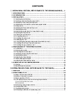
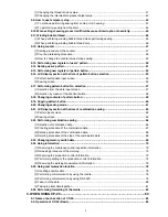
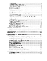
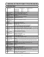
background image

* "CompactFlash(TM)" is the registered trademark of SanDisk Corporation, U.S.A.

ENGLISH

INStructIoN MaNuaL

aMS-210E / IP-410

aMS-210E / cP-20

Summary of Contents for AMS-210E/CP-20

Page 1: ... CompactFlash TM is the registered trademark of SanDisk Corporation U S A ENGLISH INStructIoN MaNuaL aMS 210E IP 410 aMS 210E cP 20 ...

Page 2: ...neumatic type only 16 3 16 Installing the eye protection cover 16 4 PREPARATION OF THE SEWING MACHINE 17 4 1 Lubrication 17 4 2 Attaching the needle 18 4 3 Threading the machine head 18 4 4 Installing and removing the bobbin case 19 4 5 Installing the bobbin 19 4 6 Adjusting the thread tension 20 4 7 Intermediate presser height 21 4 8 Adjusting the thread take up spring 22 5 OPERATION OF THE SEWIN...

Page 3: ...ction by means of the shortcut button 58 2 18 Changing contents of pattern button 59 2 19 Copying pattern button 60 2 20 Changing sewing mode 61 2 21 LCD display section at the time of combination sewing 62 1 Pattern input screen 62 2 Sewing screen 64 2 22 Performing combination sewing 66 1 Selection of combination data 66 2 Creating procedure of the combination data 67 3 Deleting procedure of the...

Page 4: ...nd change of the memory switch 100 3 11 Correspondence table of LED and 7 segment display 101 4 MEMORY SWITCH DATA LIST 104 4 1 Data list 104 4 2 Initial value list 110 5 ERROR CODE LIST 112 6 MESSAGE LIST 118 MAINTENANCE OF SAWING MACHINE 121 1 MAINTENANCE 121 1 1 Adjusting the height of the needle bar Changing the length of the needle 121 1 2 Adjusting the needle to shuttle relation 121 1 3 Adju...

Page 5: ...e by increasing decreasing either stitch length or the number of stitches Only increase decrease of stitch length when pattern button is selected and CP 20 is used 17 Max sewing speed limitation 200 to 2 700 rpm Scale 100 rpm steps 18 Pattern selection facility Pattern No selection method EEPROM 1 to 200 Media 1 to 999 CP 20 is the scroll type 19 Bobbin thread counter UP DOWN method 0 to 9 999 20 ...

Page 6: ...ATION 1 Machine head 2 Wiper switch 3 Temporary stop switch 4 Feeding frame 5 Intermediate presser 6 Thread stand 7 Operation panel IP 410 or CP 20 8 Power switch 9 Control box 0 Foot pedal 1 Manual pedal Excluding pneumatic type 1 2 3 4 6 7 8 9 0 5 1 ...

Page 7: ...nal indentation on the head 5 spring washer 6 and plain washer 7 supplied with the machine 1 Installing the power switch Fix power switch 1 under the machine table with wood screws 2 Fix the cable with staples 3 supplied with the machine as accessories in accordance with the forms of use Five staples 3 including the staple for fixing the operation panel cable are supplied as accessories 3 2 Instal...

Page 8: ...0V White Power source cord Power switch GND AC200 V AC220 V AC240 V Connecting three phase 200V 220V and 240V Red White Black Green Yellow Red Black White 1 Fit the holes of hinges A to the holes of table and fix as shown in the figure 3 3 Installation of the sewing machine head In case of the pneumatic type fix solenoid valve installing plate 1 as well WARNING To prevent possible accidents caused...

Page 9: ... pipe 5 until it will go no further so that it does not come off drain bin 4 when tilting the machine head 2 Remove the tape fixing drain pipe 5 1 2 4 6 6 6 6 3 6 5 7 6 8 3 5 Safety switch 1 Remove tape 2 fixing the lever section of safety switch 1 1 When using the safety switch without removing tape 1 it is very dangerous since the sewing machine works even in the state that it is tilted 2 In cas...

Page 10: ...ate auxiliary cover setscrews 5 and washers 4 When using areas 1510 and 2206 1 Temporarily fix throat plate auxiliary supports A 2 and B 3 to the machine bed with setscrews M5 6 and throat plate auxiliary support C 9 to the ma chine bed with setscrew M6 0 2 Move the cloth feed base to the rear and place throat plate auxiliary cover 1 from between lower plate 7 and throat plate 8 At this time be ca...

Page 11: ...ews 5 and nuts small 4 4 Temporarily fix throat plate auxiliary cover support 1 to the machine bed with setscrews M6 2 5 Temporarily fix throat plate auxiliary cover base 3 to throat plate auxiliary cover support 1 with setscrews 4 and nuts large 5 6 Fix throat plate auxiliary cover 1 with throat plate auxiliary cover setscrews 5 and nuts large 5 1 4 3 5 6 2 4 8 7 Area 2210 1 Be careful so as not ...

Page 12: ...n the table with wood screws 2 and pass the cable through table hole 4 Fix the operation panel on panel installing plate 1 with screws 3 supplied as accessories Fix the cable on the bottom surface of the table with the staples supplied with the machine as ac cessories 2 Installing the CP 20 3 7 Installing the panel 1 Installing the IP 410 4 3 1 2 1 Open cover 1 and remove cable 2 once Then connect...

Page 13: ...akage of the components will be caused 4 2 3 6 5 A 1 6 When using areas 2206 and 2210 1 Remove throat plate auxiliary cover 6 from the sewing machine 2 Hold inserting section A of the ma chine bed by hand and quietly raise it until bed support rubber 3 comes in contact with the table 3 After returning the sewing machine to its home position refer to 3 6 Installing the throat plate auxilia ry cover...

Page 14: ...t caught between the rear cover and the electrical box main body close the rear cover while pressing section A on the lower side of the rear cover and tighten four screws 1 2 Lower downward the cord located on the side of the control box and cord presser plate C in the push hole B press the cord and tighten screws 2 3 1 2 1 1 1 2 How to remove the cord clamp 2 A B 1 When fixing the cord with the c...

Page 15: ... 2P 2P 2P 2P 2P CN51 10P 10P 1 1 2 2 3 3 4 4 5 CN51 3P CN88 2P 2P 2P 2P 2P 10P 10P 1 1 2 2 3 3 4 4 5 1306 1510 IP 410 CP 20 Wiring diagram of circuit board Yellow Blue Red White White Gray Gray White Gray White White White Black White White Air SW Air solenoid valve White White White White White White White White White Sewing machine head Operation panel Foot switch SDC p c b MAIN p c b ...

Page 16: ...CN51 White CN52 White CN73 White CN84 Black CN74 White CN72 Blue CN31 White CN39 Yellow CN14 White CN16 White Ground wire 3 12 Installing the motor cover 1 Install motor cover 1 on the machine main unit with screws supplied with the machine as acces sories ...

Page 17: ...igure Slack 3 14 Connecting the pneumatic components Pneumatic type only 1 Install regulator 1 to installing plate 2 and install it to the stand with screw 3 washer 4 and nut 5 2 Connect the cord coming from the regulator with CN78 air relay cable Refer to 3 11 Wiring diagram of circuit board p 11 1 2 3 4 5 3 Install solenoid valve asm 8 to solenoid valve installing plate 6 using setscrew 7 suppli...

Page 18: ... control box to the position as shown in the figure At this time be careful of the number and alphabet of the air tubes and the cords Adjust the alphabet of the air tubes to the alphabet of the solenoid valve Also adjust the figures to the figures of the connector label 6 Connect solenoid valve asm 8 and the regu lator using long air tube supplied 1 as acces sories When the cable sags fix it to th...

Page 19: ...r tube 6 with label of 1B 2B Y type joint 8 connected with the label of 4 of mechanical valve unit 6 8 7 5 3 1 A 2A 4 1B 2B 8 9 Connector CN1 Connector CN2 A Stop plug Stop plug B 7 Install the air tube coming from mechanical valve unit 7 to A and that from 8 to B re spectively Install two stop plugs supplied as accessories and the cords coming from the control box to the places in the figure When...

Page 20: ... taching it on face plate cover 3 with screw 2 3 15 Installing the air hose Pneumatic type only 1 2 Close Open 1 Connecting the air hose Connect the air hose to the regulator 2 Adjustment of air pressure Open air cock 1 pull up and turn air adjust ment knob 2 and adjust so that air pressure indicates 0 35 to 0 4 MPa Max 0 55 MPa Then lower the knob and fix it Close air cock 1 to expel air ...

Page 21: ...ith oil is only for lubricating to the hook portion It is possible to reduce the oil amount when the number of rotation used is low and the oil amount in the hook portion is ex cessive Refer to 1 9 Amount of oil supplied to the hook p 126 1 Do not lubricate to the places other than the oil tank and the hook of Caution 2 below Trouble of components will be caused 2 When using the sewing machine for...

Page 22: ...sert it into the hole in the needle bar and tighten setscrew 1 When tightening setscrew 1 be sure to use the screwdriver Part No 40032763 supplied as accessories Do not use L shaped hexagon wrench key There is a danger of breaking setscrew 1 1 5mm 4 3 Threading the machine head WARNING Turn OFF the power before starting the work so as to prevent accidents caused by abrupt start of the sewing machi...

Page 23: ...5 cm WARNING Turn OFF the power before starting the work so as to prevent accidents caused by abrupt start of the sewing machine 1 Set the bobbin 1 into bobbin case 2 in the di rection shown in the figure 2 Pass the thread through thread slit 3 of bob bin case 2 and pull the thread as it is By so doing the thread will pass under the tension spring and be pulled out from thread hole 4 3 Pass the th...

Page 24: ...g screen 2 Set needle thread tension with TEN keys B There is a setting range of 0 to 200 When the set value is increased the tension becomes higher When the set value is 50 at the time of standard delivery the thread tension is adjusted so that H type is 2 35N and S type is 1 47N spun thread 50 When thread tension No 1 is released CP 20 1 Select thread tension with key 2 Set needle thread tension...

Page 25: ...ge of the intermediate presser is up to the standard of 3 5 mm However when using DP X 17 needle for H type or the like the setting range can be changed up to max 7 mm with memory switch U112 2 When increasing the height of intermediate presser or making the needle size thicker confirm the clearance between the wiper and the components Wiper cannot be used unless the clearance is secured In this c...

Page 26: ...ad take up spring Turning it counterclockwise will de crease the pressure In case of 2P pedal 1 Set a workpiece on the sewing machine 2 Depress the pedal switch A and the feeding frame will come down Depress it again and the feeding frame will go up 3 Depress the pedal switch B after the feeding frame has come down and the sewing machine will start sewing 4 After the sewing machine completes sewin...

Page 27: ...ESL AMS 210EHS AMS 210EHL Thread clamp unit type S type H type U70 0 Front standard 0 Front standard or 1 Rear Regarding H type thread clamp unit Change the set value of memory switch U69 in accordance with the thickness of needle thread The set value has been set to 1 H type thin thread at the time of delivery Commendable value is Set value 1 for thread count 50 to 8 and that is Set value 3 for t...

Page 28: ...th but cut the con nected needle thread with scissors or the like The seams cannot be broken because of the needle thread at the start of sewing 1 3 2 When the thread clamp is used and bobbin thread at the sewing start appears on the right side of material reduce thread tension at the sewing start 2 to 3 stitches and bobbin thread becomes less conspicuous Example of setting Tension of 1 to 2 stitc...

Page 29: ...g the data M3 data of AMS 210D series with AMS 210E There are two ways to use M3 data with AMS 210E 1 Reading by using IP 410 Use PC personal computer and copy file AMS AMS00xxx M3 of M3 from floppy disk of AMS D to AMS of media Insert the media to IP 410 and select Pattern No xxx from M3 data 2 Changing to vector format data using PM 1 Change to the vector format data with PM 1 For the details re...

Page 30: ...anel 1 When the inserting direction is wrong panel or media may be damaged 2 Do not insert any item other than the CompactFlash TM 3 IP 410 corresponds to the CompactFlash TM of 2GB or less 4 IP 410 corresponds to the format FAT16 of CompactFlash TM It does not correspond to FAT32 5 Be sure to use the CompactFlash TM which is formatted with IP 410 For the formatting procedure of the CompactFlash T...

Page 31: ... procedure of the media IP 410 Cautions when using the media Do not wet or touch it with wet hands Fire or electric shock will be caused Do not bend or apply strong force or shock to it Never perform disassembling or remodeling of it Do not put the metal to the contact part of it Data may be disappeared Avoid storing or using it in the places below Place of high temperature or humidity Place of de...

Page 32: ...n and the information screen can be performed 4 COMMUNICATION key Changeover of the data input screen and the communication screen can be performed 5 MODE key Changeover of the data input screen and the mode changeover screen which performs various detail settings can be performed 6 Media slot Close the cover for use 7 Connector for RS 232C communication 8 Variable resistor for color LCD screen co...

Page 33: ...utton This button scrolls the button or the display in the downward direction RESET button This button performs the release of error NUMERAL INPUT button This button displays ten keys and input of numerals can be performed CHARACTER INPUT button This button displays the character input screen Refer to 2 14 Naming users pattern p 51 RESSER LOWERING button Presser is lowered and the presser lowering...

Page 34: ...whenever the power is turned ON 2 Select the pattern No you desire to sew When the power is turned ON the data input screen is dis played Pattern No button A whichs selected at present is displayed in the center of the screen Press the button to se lect the sewing shape For selecting procedure of the sewing shape refer to 2 5 Performing sewing shape selection p 36 When READY key B is pressed the b...

Page 35: ...g frame needle interferes with the feeding frame during sewing and there is a danger of needle breakage or the like 2 When the presser is going up be careful that your fingers are caught with the presser since the presser moves after coming down 3 When turning OFF the power without pressing READY key the set value of Pattern No X enlargement reduction ratio Y enlargement reduction ratio Max sewing...

Page 36: ...n new register screen is displayed Refer to 2 13 Performing new register of users pattern p 50 Pattern button name input screen is displayed Refer to 2 14 Naming users pattern p 51 Effective ineffective of thread clamp is selected Thread clamp ineffective Thread clamp effective Intermediate presser is lowered and the intermediate presser reference value change screen is displayed Refer to 2 6 Chan...

Page 37: ...witch X actual size value setting button is displayed Refer to 2 6 Changing item data p 38 Scale rate in X direction of sewing shape being selected at present is displayed on this button When the scale input is set to non selection by setting memory switch the button goes out and the X scale is displayed Refer to 2 6 Changing item data p 38 Actual size value in Y direction of sewing shape being se...

Page 38: ...played Refer to 2 10 When setting of sewing product is difficult because of interruption of needle tip p 45 Effective ineffective of the thread clamp is selected Thread clamp ineffective Thread clamp effective Intermediate presser is lowered and the intermediate presser reference value change screen is displayed Refer to 2 6 Changing item data p 38 This button returns the presser to the start of s...

Page 39: ... selected at present is displayed Displayed only when the sewing shape being selected is the standard pattern Existing counter value is displayed on this button When the button is pressed the counter value change screen is displayed Refer to 2 12 Using counter p 47 Display of sewing counter No of pcs counter can be changed over Refer to 2 12 Using counter p 47 Step sewing screen is displayed Check...

Page 40: ...e kind of sewing shape There are 4 kinds below of the sewing shape Select the kind you desire from among them Pictograph Name Users pattern Vector format data M3 data Sewing standard format Maximum number of patterns 200 999 999 999 Select the sewing shape you desire from SEWING SHAPE SELECTION buttons E and press ENTER F button The sewing shape list screen corresponding to the kind of sewing shap...

Page 41: ...the sewing shape When ENTER button I is pressed the sewing shape is determined and the data input screen is displayed When the sewing shape is users pattern the screen as A is displayed PATTERN NO SELECTION button J that is registered to users pattern is displayed Press the button of PATTERN NO you desire to select A In addition when you desire to confirm the selected shape press VIEWER button K a...

Page 42: ...t under Enlargement and reduction function mode enlargement and reduction can be performed with in crease decrease of pitch When X Y scale rate is individually set in case of circle or arc or X Y enlargement and reduction are repeated the sewing is changed to point sewing and the shape may not be kept Enlargement and reduction can be performed by increase decrease of pitch In this case set and rea...

Page 43: ...ut performing sewing is not stored in memory 3 When operation processing cannot be performed since the reduction ratio is exces sively small E045 Pattern data error is displayed 4 When the scale rate is changed with increase decrease of number of stitches pitch is fixed mechanical control command inputted to the points other than the shape point is deleted H I When X Y enlargement reduction ratio ...

Page 44: ...e screen returns to the sewing screen When the checking of the shape is not in the position of the start of sewing or that of the end of sewing press the foot switch Then it is possible to sew from the midway of checking The sewing machine does not start even when the foot switch is depressed with this mode 2 Display the step sewing screen When STEP SEWING button B is pressed the step sewing scree...

Page 45: ... tension command in the front or rear When you desire to stop press STOP button H When RETURN TO ORIGIN button I is pressed the presser moves to the origin The value which is displayed is the absolute value thread tension value thread tension command value Input the value you desire with TEN keys and keys J When ENTER button K is pressed the data is deter mined Thread tension value and intermediat...

Page 46: ...ar When you desire to stop press STOP button H When RETURN TO ORIGIN button I is pressed the presser moves to the origin The value which is displayed is the absolute value intermediate presser height value inter mediate presser increase decrease value Input the value you desire with TEN keys and keys J When ENTER button K is pressed the data is deter mined 1 When checking the needle or performing ...

Page 47: ...DIATE PRESSER UP DOWN button C FEED BACKWARD button D FEED FORWARD button E and RETURN TO ORIGIN button F are displayed in the screen 1 When the presser is raised and the operation is stopped on the way because of the trouble of for getting to enter the bobbin case or the like press PRESSER UP button G and turn OFF the power 2 PRESSER UP button G is not displayed when the presser is of pneumatic t...

Page 48: ...M button B to perform thread trim ming When PRESSER UP button G is pressed the presser goes up Turn OFF the power since the operation afterwards cannot be performed When thread trimming is performed INTERMEDIATE PRESSER UP DOWN button C FEED BACKWARD button D FEED FORWARD button E and RETURN TO ORIGIN button F are displayed in the screen 1 When the presser is raised and the operation is stopped on...

Page 49: ...RN BUTTON MOVE button A is pressed the pattern button move screen is displayed 2 10 When setting of sewing product is difficult because of interruption of needle tip A 2 Move the pattern Lower the presser and input the move direction with DIREC TION key B B ...

Page 50: ...button B and the sewing machine stops and returns to the normal mode Or depress the start pedal again during winding bobbin and the sewing machine stops while the bobbin thread winding mode stays as it is Depress the start pedal again and the bobbin winding starts again Use this way when winding bobbin thread around plural bobbins Bobbin winder does not work immediately after turning ON the power ...

Page 51: ...ounter UP counter Every time the sewing of one shape is performed the existing value is counted up When the existing value is equal to the set value the count up screen is displayed DOWN counter Every time the sewing of one shape is performed the existing value is counted down When the existing value is reached to 0 the count up screen is displayed No of pcs Counter UP counter Every time one combi...

Page 52: ...nput screen is displayed 4 Change of counter existing value In case of the sewing counter press button F and in case of the No of pcs counter press button G and the existing value input screen is displayed Here input the existing value Here input the set value When 0 is inputted in the set value the display of count up screen is not performed D E F G ...

Page 53: ...unter value change screen When you desire to revise the counter value during sewing work due to the mistake or the like press COUNTER VALUE CHANGE button A on the sewing screen The counter value change screen is displayed 2 Count up releasing procedure When the count up condition is reached during sewing work the count up screen is displayed and the buzzer beeps Press CLEAR button A to reset the c...

Page 54: ...ng new register of users pattern 3 Input the users pattern No Input the users pattern No you desire to newly register with the ten keys B It is possible to retrieve the users pattern No which has not been registered with the or button C and D 4 Determine the users pattern No Press ENTER button E to determine the users pattern NO to be newly registered and the data input screen at the time of users...

Page 55: ...ou desire to input and the input of character can be performed As many as 14 characters of characters to and to and symbols and can be inputted The cursor can be moved with CURSOR LEFT TRAVEL button C and CURSOR RIGHT TRAVEL button D When you desire to delete the inputted character adjust the cursor to the position of the character you desire to delete and press DELETE button E 4 Finish the input ...

Page 56: ...ch has been already registered is prohibited It is possible to retrieve the pattern button No which has not been registered with the or button C and D 4 Select the folder to be stored It is possible for the pattern buttons to be stored in five folders As many as 10 pattern buttons can be stored for one folder The folder to store the button can be selected with FOLDER SELECTION button E 5 Determine...

Page 57: ...g users pattern p 51 Character which is registered to the pattern button No being selected is displayed Bobbin thread can be wound Refer to 2 11 Winding bobbin thread p 46 Pattern button No being selected at present is displayed on this button and when the button is pressed the pattern button No selection screen is displayed Refer to 2 17 Performing pattern button No selection p 57 Sewing shape wh...

Page 58: ... being selected is displayed Thread tension value which is registered to the pattern button No being selected is displayed Travel amount in X direction which is registered to the pattern button No being selected is displayed Travel amount in Y direction which is registered to the pattern button No being selected is displayed X actual size value which is registered to the pattern button No being se...

Page 59: ...ng sewing is displayed Character which is registered to the pattern button No being sewn is displayed Scale rate in X direction which is registered to the pattern button No being sewn is displayed Actual size value in X direction which is registered to the pattern button No being sewn is displayed Effective ineffective of thread clamp is selected Thread clamp ineffective Thread clamp effective W S...

Page 60: ...ed to the pattern button No being sewn is displayed Total number of stitches of sewing shape which is registered to the pattern button No being sewn is displayed Needle thread tension value which is set to the pattern data being selected at present is displayed on this button and when the button is pressed the item data change screen is displayed Refer to 2 6 Changing item data p 38 Travel amount ...

Page 61: ...d pattern button No buttons C which have been registered are changed over in order The contents of sewing data which have been inputted in the pattern button No are displayed in the button Here press the pattern button No button C you desire to select 4 Determine the pattern button No When ENTER button D is pressed the pattern button No selection screen is closed and the selection is finished Howe...

Page 62: ...splayed with every folder which is specified when the pattern is newly created When FOLDER SELECTION button B is pressed the pattern button to be displayed is changed Display and press the button of the pattern button No you desire to sew When it is pressed the pattern button No is selected WARNING Make sure without fail of the contour of the sewing pattern after selection of the sewing pattern If...

Page 63: ...direction can be changed to the actual size value input by selection of memory switch Max input range and initial value of max speed limitation D are determined with memory switch The input range of travel amount in X direction F and travel amount in Y direction G differs accord ing to the sewing range 3 Display the input screen of the item data you desire to change Data that can be changed are 11...

Page 64: ...the pattern copy screen When PATTERN BUTTON COPY button A is pressed the pattern button copy copy source selection screen is dis played 4 Determine the change of item data For example input X scale rate Press B to display the item data input screen Input the value you desire with the ten keys or or key K When ENTER button L is pressed the data is determined 5 Close the pattern button data change s...

Page 65: ...ton No in the selection state returns to the pattern button copy copy source selection screen after ap proximately two seconds Combination data can be copied in the same way 2 20 Changing sewing mode 1 Select the sewing mode When switch is pressed in the state that the pattern has been registered SEWING MODE SELECTION button A is displayed on the screen When this button is pressed the sewing mode ...

Page 66: ...ON DATA NEW REGISTER button COMBINATION DATA COPY button COMBINATION DATA NAME INPUT button COMBINATION DATA NAME display PRESSER DOWN button BOBBIN WINDING Description Combination data No new register screen is displayed Refer to 2 15 Performing new register of pattern button p 52 Combination pattern No copy screen is displayed Refer to 2 19 Copying pattern button p 60 Combination data name input...

Page 67: ... displayed Sewing order of the inputted pattern data is displayed When the screen is changed over to the sewing screen the pattern which is sewn first is displayed in blue color Pattern No shape number of stitches etc which are registered in H SEWING ORDER are displayed on the button When the button is pressed the pattern selection screen is displayed When the patterns which are registered to the ...

Page 68: ...elected Thread clamp ineffective Thread clamp effective Presser can be lowered and the presser down screen is displayed To raise the presser press the presser up button displayed in the presser down screen Presser can be returned to the start of sewing and is raised at the time of temporary stop Combination data No being selected is displayed Pattern button No being sewn is displayed Sewing shape ...

Page 69: ...nter value is displayed on this button When the button is pressed the counter value change screen is displayed Refer to 2 12 Using counter p 47 Display of sewing counter No of pcs counter can be changed over Refer to 2 12 Using counter p 47 X actual size value of the sewing shape which is registered to pattern button No being sewn is displayed X scale rate of the sewing shape which is registered t...

Page 70: ...ata No which is selected at present and the con tents are displayed in the upper part of the screen and other combination data No buttons which have been registered are displayed in the lower part of the screen 3 Select the combination data No When UP DOWN button B is pressed combination data No buttons C which have been registered are changed over in order Here press the combination data No butto...

Page 71: ... No selection screen is displayed 3 Select the pattern No When UP DOWN SCROLL button B is pressed pattern No buttons C which have been registered are changed over in order The contents of pattern data are dis played in the buttons Here press the pattern No buttons you desire to select 4 Determine the pattern No When ENTER button D is pressed the pattern No se lection screen is closed and the selec...

Page 72: ...tep of the combination data 1 Select the combination data No Perform steps 1 to 2 of 2 22 1 Selection of combina tion data p 66 to make the state that the combination data including the step you desire to delete has been selected 2 Display the pattern No selection screen When PATTERN SELECTION button A of the step you desire to delete is pressed the pattern No selection screen is displayed 3 Perfo...

Page 73: ... 4 MEMORY SWITCH DATA LIST p 104 D 2 23 Changing memory switch data 1 Display the memory switch data list screen When MODE key is pressed memory switch button A is displayed on the screen When this button is pressed the memory switch data list screen is displayed 2 Select the memory switch button you desire to change Press UP DOWN SCROOL button C and select the data item button B you desire to cha...

Page 74: ...fer to 2 24 3 Observing the production control information p 72 and 2 24 4 Performing setting of the production control information p 74 3 Information on machine working ratio pitch time machine time and machine speed can be displayed from the working state of the sewing machine Refer to 2 24 5 Observing the working measurement information p 76 1 Observing the maintenance and inspection informatio...

Page 75: ... at E In addition remaining time up to the replacement can be cleared 3 Perform clearing remaining time up to the replacement When button C of the item you desire to clear is pressed the time of replacement clear screen is displayed When CLEAR button F is pressed the remaining time up to the re placement is cleared D E C F 4 Display the threading diagram When threading button G displayed in the ma...

Page 76: ...tion refer to the item of 1 12 Replenishing the designated places with grease p 128 When displaying from the information screen 3 Observing the production control information It is possible to designate the start display the number of pieces of production from the start to the ex isting time display the number of pieces of production target etc in the production control screen There are two kinds ...

Page 77: ...er of pieces of the target of products at the present time is automatically displayed B Actual results value Number of pieces of the sewn products is automatically displayed C Final target value Number of pieces of the final target of products is dis played Input the number of pieces referring to 2 24 4 Performing setting of the production con trol information p 74 D Pitch time Time second require...

Page 78: ... thread trimming per pro cess When number of times of thread trimming button C in the previous page is pressed the number of times of thread trimming input screen is displayed Input the value you desire with ten keys or UP DOWN buttons After the input press ENTER button F When the input value is 0 count of the number of times of thread trimming is not performed Use this function by connecting the ...

Page 79: ...ton I is displayed at the position of STOP button When continuing the count press START button I again The counted value is not cleared until CLEAR button K is pressed 7 Clear the counted value When clearing the counted value set the count to the stop state and press CLEAR button L The value to be cleared is the present target value M and ac tual results value N only CLEAR button is displayed only...

Page 80: ...t of measuring the machine speed C The information is automatically displayed from the time of start of measuring the pitch time D The information is automatically displayed from the time of start of measuring the machine time E Number of times of thread trimming is Input the number of times referring to item 3 on the next page 3 Input the number of times of thread trimming Next input the number o...

Page 81: ...tart the measurement When START button D is pressed measurement of each data is started 5 Stop the count Display the working measurement screen referring to 1 and 2 of 2 24 5 Observing the working measurement infor mation p 76 STOP switch E is displayed when the measurement is being performed When STOP switch E is pressed the measurement is stopped After the stop START button D is displayed at the...

Page 82: ...sonal computer 1 Handling possible data Sewing data that can be handled are 4 kinds below and the respective data formats are as shown be low Data name Vector format data M3 data Sewing standard format data Simplified program data Extension VD00XXX VDT AMS0XXX M3 SD00XXX DAT AMS0XXX PRO Description of data It is the data of needle entry point created with PM 1 and the data format that can be opera...

Page 83: ... by hand and control so that dust oil or other foreign material does not adhere to it In addition the inside element is damaged by static electricity or the like So be very careful when handling When the lower part of the cover located on the side of the operation panel is opened there is the connector of 9 pin for RS 232C Connect the cable there When the screw for locking is attached to the conne...

Page 84: ...nication screen is displayed 2 Select the communication procedure There are four communication procedures as described below B Writing data from media to panel C Writing data from personal computer server to panel D Writing data from panel to media E Writing data from panel to personal computer server Select the button of communication procedure you desire 3 Select the data No When F is pressed th...

Page 85: ... selection screen When PLURAL SELECTION button A is pressed the data No plural selection screen is displayed 2 Perform the data No selection Since the list of existing data file numbers is displayed press FILE NO button B you desire to write It is possible to invert the selected state of the button with INVERSION button C 3 Determine the data No When ENTER button D is pressed the data No plural se...

Page 86: ... in the during communication screen When performing writing to the pattern No which already ex ists the overwriting confirmation screen is displayed before writing When performing overwriting press ENTER button F When performing overwriting all without displaying the over writing confirmation screen press OVERWRITING button G in all cases ...

Page 87: ...en re formatting the media be sure to perform it with IP 410 or IP 400 The media that is formatted with the personal computer cannot be read with IP 410 and the CP 20 B A 2 Start formatting of the media Set the media you desire to format to the media slot close the cover press ENTER button B and formatting starts Save necessary data in the media to the other media before formatting When formatting...

Page 88: ...elected item and the set value are displayed 7 Data indication LED This LED indicates the set values of the se lected items such as pattern No X Y scale etc 8 Item selection LED LED of the selected items light up 9 Needle thread clamp ON OFF key This key selects effective ineffective of needle thread clamp When it is effective needle thread clamp display LED lights up 0 Needle thread clamp display...

Page 89: ...tern No 1 Turn ON the power switch Pattern No of the item selection lights up and the pattern No is indicated on the data display 2 Setting of the pattern No Example when setting pattern No S 61 1 Press the key to indicate the item Pat tern NO 2 Press the or key to indicate S 61 on the display Be sure to use the smart media that has been formatted with IP 400 For the formatting procedure of the sm...

Page 90: ...n 0 to 3 5 Max 0 to 7 0 can be set 6 Setting the thread tension Example when setting thread tension 30 1 Press key to indicate the item THREAD TENSION 2 Press or key to indicate 30 0 to 200 can be set 4 Setting of the Y scale Example when setting 100 0 1 Press the key to indicate the item Y Scale 2 Press or key and set the ratio within the range of 1 0 to 400 0 Setting range can be changed with me...

Page 91: ...2 After the work clamp feet have moved and gone up the sewing LED lights up and the sewing is ready 1 When the data is changed press to confirm the change 2 When selecting the items of the height of the intermediate presser and the bobbin winder the machine cannot move to the sewing state Select other items 3 If key is pressed you can make sure of the respective setting items again How ever the it...

Page 92: ...flashes on and off 4 Set the thread tension reference value with key or key Changing the thread tension command value 1 Press key in the aforementioned refer ence value change state 2 Both the sewing LED and the thread tension LED flash on and off 3 Continue stitching with key or key 4 C is displayed when there is the thread tension command in the current needle entry point 5 Pressing key set the ...

Page 93: ... off 3 Continue stitching with key or key 4 C is displayed when there is the intermedi ate presser command in the current needle entry point 5 Pressing key set the intermediate presser command value with key or key 6 When ending the setting press key h h h 1 When checking the needle or performing the feed forward or backward the ma chine fails to work unless the presser is lowered Use the machine ...

Page 94: ...r to store the changed pattern see 3 3 Performing copying of pattern p 90 3 3 Performing copying of pattern Copying below can be performed under the pattern copy mode Copying from vector format data to users pattern Copying between vector format data Copying from users pattern to vector format data Copying between users patterns 1 Confirm that sewing LED went out and press key Display the copy mod...

Page 95: ...en registered When No can be selected determine it with key 4 When trying to copy to the registered pat tern No the overwriting confirming state is produced When performing the overwriting press key and when canceling press key 3 4 Performing deletion of pattern 1 Confirm that the sewing LED has gone out and press key Display the deletion mode and press key with key or key 2 Set the deletion No Se...

Page 96: ...he work clamp feet during sewing causing dangerous troubles including needle breakage 1 Make the Sewing LED go off with key 2 Press key and select the item of pattern No 3 Set the pattern No with key or key 4 Similarly setting of X Y scale speed etc is performed 5 When key is pressed the Sewing LED lights up and the sewing machine is in the sewing ready state 3 The deletion confirmation state is p...

Page 97: ...e pedal switch is depressed the sew ing machine rotates 5 When the pedal is depressed again or key or key is pressed the sewing machine stops When winding bobbin ends with key the winding bobbin mode is completed 6 When key is pressed the Sewing LED goes off the work clamp feet go up and key becomes effective WARNING Make sure without fail of the contour of the sewing pattern after selection of th...

Page 98: ...4 P5 P4 P4 P11 P2 P4 P18 P1 P2 P5 P25 P3 P4 P5 P5 P5 P12 P2 P5 P19 P1 P3 P4 P6 P1 P2 P13 P3 P4 P20 P1 P3 P5 P7 P1 P3 P14 P3 P5 P21 P1 P4 P5 4 Press key Select P No to be regis tered Selection can be performed with or key 5 Press key to indicate the Pattern No Set the Pattern No to 3 with or key 2 Register to the pattern key Setting example Register following setting to the P2 Pattern No 3 X scale ...

Page 99: ...s When key is pressed the set data is canceled 10 Press key Mode setting is finalized and the mode returns to the normal mode 8 Press key and Y Scale rate indication becomes 0 0 Traveling amount in Y direction can be set in 0 1 mm unit Set 1 0 with or key 6 Press key and set as follows with or key X Scale rate 50 0 Y Scale rate 80 0 Max speed limitation 2000 rpm Thread tension 50 Presser height 0 ...

Page 100: ...f a sewing pattern p 87 5 If the contour of the sewing pattern is accept able the sewing can be made 6 Press key after completion of sewing and the presser comes down The presser moves to the sewing start point after origin retrieval and goes up The P keys can operate the pattern change by one touch even when the sewing LED is lighting up 7 Perform the above items 4 and 5 The P1 to P50 can be indi...

Page 101: ... switch set ting 2 Indicate the combination mode with or key 3 Press key Sewing LED lights up to enter the combination mode C1 to C20 can be selected with or key When the space after C1 is blank the data is in the registered state When the space after C1 is the data is not in the registered state 4 Press key and then press key P1 is set to the first pattern of C1 5 Press key and then press key P2 ...

Page 102: ...wing the step returns to the first step The sewing can be made repeatedly 1 When you desire to return the pattern to the previous one or skip the next pattern after sewing press or key in a state that the sewing LED lights up The indication of the pattern will change and the work clamp feet will move to the sewing start point 2 If the contents of P1 to P25 are changed after registration of C1 to C...

Page 103: ...e does not start even if depressing the pedal 6 Replace the bobbin with a new one and press the key The value of the counter returns to the set value 7 Repeat the steps of procedure from the steps 4 to 6 The counter at the time of delivery is set to the production counter adding method If it is used as the bobbin thread counter it is necessary to change over memory switch Refer to the item 3 10 St...

Page 104: ... to the No you desire to change and press key The sewing LED lights up 4 Change the contents of the memory switch with or key 5 The value can be returned to the value at the time of delivery from the factory with key 6 Press key to register the contents of change Sewing LED goes off and the mode returns to the selective state of the memory switch No 7 Press key to finalize the memory switch settin...

Page 105: ... Cycle pattern Example Cycle pattern 1 X enlargement reduction ratio display Example 100 0 Y enlargement reduction ratio display Example 100 0 Max number of revolutions display Example 2 700 rpm Thread tension display Example 50 Intermediate presser height When presser goes up Example 1 5mm Intermediate presser height When presser comes down Example 1 5mm Pattern in the smart media is indicated Pa...

Page 106: ...tern the contents of which are changed display Example Smart media pattern 20 Confirmation display when changing No of smart media pattern the contents of which are changed Overwriting confirmation and deletion confirmation display Memory switch display Example Memory switch No 1 set value 2700 Direct pattern register and edit display Cycle pattern register and edit display Copy Deletion It is ind...

Page 107: ...ttern 200 Deletion No selection Example Users pattern 1 Number of revolutions in the sewing state display It is possible to change the number of revolutions during sewing with key or key Change is temporary Example Max number of revolutions 2 700 rpm Number of revolutions 2 000 rpm Counter value display Example Counter value 9999 Error No display Flash Example Error No 50 It is indicated when copy...

Page 108: ...read clamp 200 to 2700 100rpm Thread tension of 1st stitch In case of with thread clamp 0 to 200 1 Thread tension setting at the time of thread trimming 0 to 200 1 Thread tension changeover timing at the time of thread trimming 6 to 4 1 Sewing speed of 1st stitch In case of without thread clamp 200 to 1500 100rpm Sewing speed of 2nd stitch In case of without thread clamp 200 to 2700 100rpm Sewing ...

Page 109: ...e timing in direction when stitch is not well tightened 8 to 16 1 State of the presser after end of sewing is selected 0 Presser goes up after moving at start of sewing 1 Presser goes up immediately after end of sewing 2 Presser goes up by pedal operation after moving at start of sewing Presser lifting motion at the end of sewing can be set 0 With presser up 1 Without presser up Origin retrieval c...

Page 110: ...can be selected Function for IP 410 only 0 input 1 Actual size input Thread tension output time when setting thread tension can be set 0 to 20 1 Bend position of thread clamp is selected 0 0 S type 1 H type thin thread 50 to 8 2 H type intermediate 3 H type thick thread 5 to 2 Thread clamp and thread clamp position selection 0 Standard Front position 1 Rear position Thread breakage detection selec...

Page 111: ...8 to 99 Solid presser Feeding frame control midway stop time open close At the time of control by motor 0 1 step 0 to 99 1 1 2 step stroke Lowering again with presser switch 2 2 step stroke Starting re lowering with start switch 3 3 step stroke Intermediate re lowering lifting with presser switch 1 4 to 99 1 step At the time of control by air 0 Solid presser 1 Right left separated presser Without ...

Page 112: ...ic thread trimming 1 Manual Thread trimming by turning Stop SW ON again Main motor X Y feed synchronized control speed pitch 0 2700rpm 3 0mm 1 2200rpm 3 0mm 2 1800rpm 3 0mm 3 1400rpm 3 0mm Intermediate presser with without control 0 Without Lowering fixed 1 With Lowering with sewing data at the time of operation 2 With Lowering even at the time of feed forward backward Intermediate presser lowerin...

Page 113: ... 7 Intermediate presser height p 21 0 to 7 0mm 0 1 With without needle cooler control 0 Without 1 With Grease up error Clearing of number of stitches of grease up is performed Refer to 1 12 Replenishing the designated places with grease p 128 Language selection 0 Japanese 1 English 2 Chinese ...

Page 114: ...ewing speed of 4th stitch In case of without thread clamp 1500 Sewing speed of 5th stitch In case of without thread clamp 2000 Thread tension of 1st stitch In case of without thread clamp 0 Thread tension changeover timing at the time of sewing start In case of without thread clamp 5 Operation panel key lock mode CP 20 only 0 Counter motion selection CP 20 only 0 Height of eight of presser at the ...

Page 115: ...f thread breakage detection 3 Feeding frame control pedal open close 0 1 0 Feeding frame control midway stop time open close 0 1 0 Pedal SW1 with without latch 1 Pedal SW2 with without latch 1 Pedal SW3 with without latch 1 Pedal SW4 with without latch 1 Enlarging reducing function mode CP 20 increasing decreasing of pitch only 1 Jog move function mode 2 Retainer compensation motion selection of m...

Page 116: ...vious screen E011 External media not inserted External media is not inserted Possible to re enter after reset Previous screen E012 Read error Data read from external media cannot be performed Possible to re start after reset Previous screen E013 Write error Data write from external media cannot be performed Possible to re start after reset Previous screen E015 Format error Format cannot be perform...

Page 117: ...ous screen E028 Write error Data write from server cannot be performed Possible to re start after reset Previous screen E029 Media slot release error Lid of media slot is open Possible to re start after reset Previous screen E030 Needle bar position missing error Needle bar is not in the predetermined position Turn hand pulley to bring needle bar to its predetermined position Data input screen E03...

Page 118: ...broken or revision is old Turn OFF the power E220 Grease up warning At the time of operation of 100 million stitches Refer to 1 12 Replenishing the designated places with grease p 128 Possible to re start after reset Data input screen E221 Grease up error At the time of operation of 120 million stitches The sewing machine is put in the sewing impossible status It is possible to clear with memorysw...

Page 119: ...type code of system is not proper in the initial communication Possible to rewrite program after pressing down communication switch Communi cation screen E704 Inconsistency of system version System software version is inconsistent in the initial communication Possible to rewrite program after pressing down communication switch Communi cation screen E730 Main shaft motor encoder defectiveness When ...

Page 120: ... c b fluctuates more than 15 Turn OFF the power E905 Heat sink temperature for SERVO CONTROL p c b abnormality Turn ON the power again after taking overheat time of SERVO CONTROL p c b Turn OFF the power E907 X feed motor origin retrieval error When origin sensor signal is not inputted at the time of origin retrieval motion Turn OFF the power E908 Y feed motor origin retrieval error When origin se...

Page 121: ...ower E917 Communication failure between operation panel and personal computer When abnormality occurs in data communication Possible to re start after reset E918 MAIN p c b overheat Overheat of MAIN p c b Turn ON the power again after taking time Turn OFF the power E925 Intermediate presser motor origin retrieval error Origin sensor of intermediate presser motor does not change at the time of orig...

Page 122: ...iting confirmation of media Overwriting is performed OK M530 Overwriting confirmation of vector data of panel M3 data sewing standard format data simplified program data Overwriting is performed OK M531 Overwriting confirmation of vector data of media M3 data sewing standard format data simplified program data Overwriting is performed OK M532 Overwriting confirmation of vector data on personal com...

Page 123: ... OK M544 Data corresponding to panel does not exist Data does not exist M545 Data corresponding to media does not exist Data does not exist M546 Data corresponding to personal computer does not exist Data does not exist M547 Overwriting prohibition on pattern data Overwriting cannot be performed since data exists M548 Overwriting prohibition on media data Overwriting cannot be performed since data...

Page 124: ...lay Display message Description M653 During formatting Formatting is performed M669 During data reading Data is being read M670 During data writing Data is being written M671 During data converting Data is being converted ...

Page 125: ...on 2 3 2 3 2 3 4 6 3 4 Marker line for DP x 5 needle 5 Marker line for DP x 17 needle with needle count higher than 22 6 Marker line for DP x 17 needle with needle count lower than 22 5 1 Relation between the needle and the marker lines on the needle bar When a DP x 5 needle is used When DP x 17 needle of which needle count is lower than 22 is used When DP x 17 needle of which needle count is high...

Page 126: ...nt Then tighten setscrew 1 4 Loosen shuttle race screw 7 and adjust the longitudinal position of the shuttle race To do this adjustment turn shuttle race adjust ing shaft 8 clockwise or counterclockwise to provide a 0 05 to 0 1 mm clearance between needle 5 and the blade point of shuttle 4 5 After adjusting the longitudinal position of shuttle race further adjust to provide a 7 5 mm clearance betw...

Page 127: ...it becomes 7 mm The vertical stroke of the intermediate presser is factory set to 4 mm at the time of delivery By removing the rubber plug in the face plate cover adjustment can be performed with out removing the face plate cover 2 1 3 Adjusting the height of the feeding frame 1 3 2 1 Loosen screws 2 located on the right and left sides of feed bracket 1 Moving cloth presser stopper 3 to the direct...

Page 128: ... clearance of 18 5 mm is provided between the front end of the throat plate and the top end of thread trimmer lever small 3 To adjust move the moving knife in the direction of arrow 2 Loosen setscrew 5 so that a clearance of 1 0 mm is provided between needle hole guide 2 and counter knife 4 To adjust move the coun ter knife Throat plate 1 2 5 4 3 1 1 WARNING Turn OFF the power before starting the ...

Page 129: ...henever the stroke of thread take up spring 2 has been changed be sure to readjust thread breakage detector plate 1 To make this adjustment loosen screw 3 Adjust so that thread breakage de tector plate 1 does not touch any adjacent metallic parts other than thread take up spring 2 When polyethylene oiler 1 becomes filled with oil remove polyethylene oiler 1 and drain the oil 1 8 Draining waste oil...

Page 130: ... time lag fuse 3 For control power supply protection 2A fast blow type fuse 1 Loosen setscrew 1 and remove setscrew 1 2 When screwing in adjustment screw 2 the amount of oil of oil pipe left 4 can be reduced 3 After the adjustment screw in setscrew 1 and fix it 1 The state of standard delivery is the position where 3 is lightly screwed in and returned by 4 turns 2 When reducing the amount of oil d...

Page 131: ...imp style terminal of AC input cord to the power plug as shown in the figure Caution Securely perform the insulation treatment to the red terminal which is not used with insulation tape or the like When the insulation is insufficient there is a danger of electric shock or leakage current C In case of using with single phase 200V to 240V Changing the changeover connector Connect to 200V the 100 200...

Page 132: ...without replenishing the places with grease after the display of error No E220 error E221 Grease up error is dis played and the sewing machine fails to operate since the error can not be released even when the RESET key is pressed When error E221 Grease up error is displayed be sure to replen ish the designated places below with grease Then call the memory switch U245 press CLEAR button A and set ...

Page 133: ...s used further for a certain period of time without replenishing the designated places with grease after display of error No E220 error No E221 is displayed and the sew ing machine fails to operate since the error cannot be released even when the RESET key is pressed When the error No E221 is displayed be sure to replenish the designated places below with grease Then start up the memory switch and...

Page 134: ...ply grease to X guide shaft 1 and the rear of presser plate 2 1 Tilt the machine head and remove the grease cover 1 2 Fill joint 4 supplied as accessories with grease from the grease tube 3 Remove setscrew 3 in oscillator gear 2 and screw in joint 4 into the screw hole 4 Screw in screw 5 supplied as accessories to the joint and replenish there with the grease 5 Securely tighten setscrew 3 which ha...

Page 135: ...s scratches Buff or replace it 3 The needle strikes the work clamp foot Correct the position of the work clamp foot 21 4 Fibrous dust is in the groove of the shuttle race Take out the shuttle and remove the fibrous dust from the shuttle race 5 The needle thread tension is too high Reduce the needle thread tension 20 6 The tension of the thread take up spring is too high Reduce the tension 22 7 The...

Page 136: ...te presser is not properly positioned in terms of the needle Adjust the eccentricity between intermediate presser and needle so that needle enters in the center of intermediate presser 8 Threads break at time of thread trimming 1 The moving knife has been improperly position Correct the position of the moving knife 124 9 The thread clamp is entangled with needle thread 1 The needle thread at the s...

Page 137: ...s S type 14 to 18 2 B242621000B ø 2 0 For medium weight to heavy weight materials H type 18 to 21 B242621000D ø 2 4 For heavy weight materials OP B242621000F ø 3 0 22 to 25 B242621000G ø 3 0 with a counterbore For extra heavy weight materials OP 18 to 25 B242621000H ø 3 0 eccentric hole For heavy weight materials to prevent skip stitching OP Needle used Intermediate presser Size Part No Size øA øB...

Reviews: