background image

From the library of: Superior Sewing Machine & Supply LLC

Summary of Contents for DDL-552-2

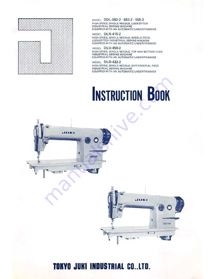
Page 1: ...NG MACHINE EQUIPPED WITH AN AUTOMATIC UNDERTRIMMER MODEL DLU 450 2 HIGH SPEED SINGLE NEEDLE TOP AND BOTTOM FEED INDUSTRIAL SEWING MACHINE EQUIPPED WITH AN AUTOMATIC UNDERTRIMMER MODEL DLD 432 2 HIGH SPEED SINGLE NEEDLE DIFFERENTIAL FEED INDUSTRIAL SEWING MACHINE EQUIPPED WITH AN AUTOMATIC UNDERTRIMMER Instruction Book Qt JUKI TSK TOKYO JOKI INDUSTRIAL CO LTO From the library of Superior Sewing Mac...

Page 2: ...When low speed sewing is not necessary 15 9 Carefully note the following points 15 10 How to select the presser foot throat plate sewing hook and feed dog 15 IV ADJUSTING THE MACHINE 16 1 Adjusting the timing of the thread trimming cam 16 2 Adjusting the position of the moving knife 17 3 How to install the fixed knife correctly 18 4 The floating range of the second thread tension disc 19 5 How to ...

Page 3: ...struction All the thread trimming mechanisms are built in inside the bed in rational order so that the sewing area is amply wide and all attachments can be used freely 2 Main specifications Sewing speed DLD 432 2 Up to 4 200 s p m Cotton Up to 4 000 s p m Synthetic Fiber DLU 450 2 Up to 4 200 s p m Cotton Up to 4 000 s p m Synthetic Fiber DLN 415 2 Up to 5 000 s p m Cotton Up to 4 000 s p m Synthe...

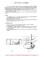
Page 4: ...ositions of the table legs motorandcontrolboxetc areclearly illustrated by the dimensional diagram which is enclosed within this book 2 Fig l shows the rear view of the set up The installed position of the control box is rather far away from the motor but thisisfor the purpose of removing the rear cover of the motor easier 2 Installing the motor 1 Stop motor automatic positioner stopping clutch mo...

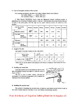
Page 5: ...0 3520 u o vo Low speed Hitachi NATIONAL 228 206 193 173 160 4 Length of the belt The length of the belt is shown in the table below Motor pulley Outer dia mm 125 5 116 5 95 5 90 5 81 0 76 0 Length of belt For Hitachi Motors 43 42 42 42 41 41 Note Put on the belt before connecting the cord which is coming out from behind the hand wheel 5 Installing the control box Install the control box to the po...

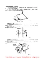
Page 6: ... by just changing the length of the connecting bar as in the case of previous lockstitch machines j Loosen the screw D of the coupling of the connecting bar and adjust by inserting and with drawing the connecting bar Fig 5 Fig 5 3 Installing the connecting bar Loosen the motor lever adjusting screw and adjust so that the motor lever and the connecting bar comes in straight line Also be sure to sec...

Page 7: ...me is increased In such a case return the thread trimming stroke adjusting screw within the area of l 3mm 3 64 l 8 At the sametime return the thread trimming switchadjusting screw and adjust so that T SW will activate at lmm 3 64 before the auxiliary lever hits the thread trimmingstroke adjusting screw and stops After the adjustment tightly tighten the locknut Do not adjust the low speed step in f...

Page 8: ...ing time If the thread trimming step in force adjustingscrewisscrewedin this force gets stronger and if returned it becomes weaker After adjustment tighten the locknut securely The reverse step in amount at the time of thread trimming is meaningless unless the installing position of the thread trimming switch must also be changed so do not make adjustment Do not adjust the step in pressure or the ...

Page 9: ... sewing to the control box and also to activate the safety device of the pedal The plugging color is blue and this is plugged in to the control box front motor side 9 pole plug 2 This is the cord for the wiper and for automatic reversesewing It transmits the signal from the reverse sewing switch and activates the wiper 6 pole plug 1 When HITACHI NATIONAL motor is used In case of motor lever switch...

Page 10: ... socket on the side of the control box and connect them to the terminals on the left side of the transformer inside the control box Connect the white and black cords to the terminals of 0 and 200V White or black cord can be connected either to the 0 or 200V terminals It cloesn t matter With the lOOV stop motor forsingle phase connect them to the 0 and lOOV terminals C How to connect the cord 6 fro...

Page 11: ...it should be short circuited if the fuse of 6A is used other electrical parts will not be damaged If over sized fuse is used the damage will be felt by other parts also and the repairing will be a tremendous job dL dl 3 Correct connection of the ground wire green There should be a ground terminal on the power sourcesocket for 3 phase 4 plugs can be inserted so be sure to connect this green ground ...

Page 12: ...at the in and out ofthe clutch by means ofthe motor lever and be careful to see that the brake friction disc does not lean to one side After the adjustment lightly push the lever toward the brake side and make the bolts M6x30 contact the brake Next firmly tighten the set screw M6xl0 again and at the same time firmly set the lock nut which is setting the bolt M6x30 If the brake friction disk is sla...

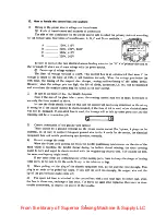
Page 13: ... transporting the machine do not touch the cover on the rear part of the hand wheel Sometimes when the power switch is turned on and the thread is trimmed but if you step on the pedal to the rear immediately after these actions the needle will not come down and trimming cannot be done In such a case just step on the pedal toward front once and the needle will come down and normal trimming can be r...

Page 14: ...tor 4 How to operate the pedal As shown in Fig 10 the pedal of this machine functions in 4 stages as follows CD The machine is stopping by just resting your foot lightly on the pedal D When the pedal is stepped on lightly to front it becomes low speed sewing D When the pedal is stepped on further strongly to front it becomes high speed sewing When the pedal is stepped on fully toward rear the mach...

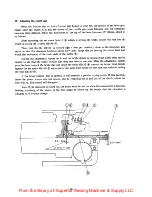
Page 15: ...n But if it is at the lowered position when thread ing the machine step on the pedal toward rear once and do the trimming action once Then the needle will go up and stops there Pass the needle thread in the order of D as shown in Fig 27 6 Adjusting the thread tension Fig 28 Adjusting the thread tension of this machine is exactly like a conventional lockstitching machine Please follow the procedure...

Page 16: ...ing might occur Be very careful As a rule this machine is used with a bobbin case in which a magnet is built in to prevent idle spinning of the bobbin Part number is D 1837555 BAO and sold separately 7 Adjusting the needle stop position after thread trimming Fig 13 After the thread is trimmed this machine can change the needle stop position To adjust to the standard needle stop position rotate the...

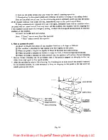
Page 17: ...g will become short and thread slipping out might result When skip stitching occurs the bobbin thread may break but the needle thread docs not break In such a case re adjust the timing of the needle with the sewing hook 10 How to selectthe presser foot throat plate sewing hook andfeed dog 1 Presser foot Select small a and b parts Fig 15 2 Throat plate Select small needle eye and A part 3 Needle Fi...

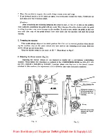
Page 18: ...ine of the arm Fig 18 D and the indicated line of the hand wheel Fig 18 D are matched together as shown in Fig 18 it becomes a cotton thread timing But if the indicating line Fig l8 D is matched with the indicating line Fig l8 D it becomes a timing for synthetic thread DLD 4322 Fig 16 Thread trimming cam Cam roller Cam roller shaft arm set screw Rotational direction Mil Rotate cam in this directio...

Page 19: ...e moving shaft adjusting nut Fig 20 D If this nut is screwed in deep the retreating range of th the knife becomes greater and if it s loosened the range gets less c Loosen both set screws of trimming cam 7 and the thrust collar 6 d Match the indicating line of the hand wheel with the indicating line of the arm In case of cotton thread match D with 2 of Fig 18 and for synthetic thread match D with ...

Page 20: ...ly The correct method of installing the fixed knife is shown in Fig 22 The standard distance from the center of the needle to the tip of the fixed knife is 4 2mm 5 32 The tip of the fixed knife should be 0 6mm above the installing surface Fig 23 When the angle of the installing fixed knife s tip is changed the cutting power changes When the cutting part of the fixed knife and the moving knife is p...

Page 21: ...ever to make the adjustment complete it is also necessaryto adjust the timing of the thread trimmer Chapt IV 1 4 The floating range of the second thread tension disc 1 How to verify the floating range At the position where the take up has come just before the upper dead point lower the presser foot and when the hook thread presser Fig 16 D is pushed hard to right verify that the floating range of ...

Page 22: ... fixed knife change the angle of the arrow mark of Fig 29 When the D side of Fig 28 does not cut well shorten the angle and when the C side does not cut well make the angle larger Shave off corners and sharpen well Sharpen this surface A surface Blade tip B surface Fig 27 Fixed knife Moving knife Fixed knife C Dparts of moving knife andfixed knife should contact each other at the same time Fig 28 ...

Page 23: ...ead presser at the trimming time shortening the thread remaining amount at the tip of the needle eye after the trimming and invites thread slipping out 1 The correct position of the bobbin thread presser When the thread trimming lever is pressed hard against the stopper side the bobbin thread should be pulled out easily At this position the clearance between the tip Bobbin presser of the bobbin th...

Page 24: ... almost touching the stopper adjust the position of the thread trimming magnet so that the snap ring which is attached to the thread trimming magnet plunger hits the rubber ring and stops and also when the magnet is pulling there should be no clearance between the two ends of the rubber ring E 20mm 13 5mm Fig 34 Fig 35 9 How to install and remove the knife installing base To remove the knife insta...

Page 25: ...ch to ON Match the black indicating lineof the pulley with the redindicating lineof the machine head D If the synchronizer is moved gently by the hand without moving the pulley the auxiliary motor will either rotate or stop So at the position where the auxiliary motor has started to stop tighten the screw D Replace the cover of the synchronizer to the original position Note When the above adjustme...

Page 26: ...r is over heated 1 Inadequate returning of the MB part 2 Inadequate lead relay contact point 3 One phase of 3 phases is disconnected Repair the clutch part with oil stone Exchange the lead relay Connector inside the motor end cover is disconnected 4 Enters into low speed running with the power source ON 1 Inadequate position of L SW switch 2 Defective L SW switch 3 12P connector of head is pulled ...

Page 27: ...and wheel toward the regular direction and as shown in Fig 37 bring the white point D of the hand wheel so that it will match with the red point D of the frame z 2inin 1mm Fig 37 Fig 38 2 Then as shown in Fig 38 insert the wiper into the driving shaft D and bring the tip of the wiper so that it will come to 2mm approx 1 16 under the point of the needle Make sure that the space between the flat sur...

Page 28: ...nd as shown in Fig 3 adjust so that the edge of the wiper comes to the position where it will be away from the needle center by 2mm approx 1 16 After this adjustment securely tighten the wiper magnet set screw 2min Fig 39 With the exception of above all operating instructions and adjustments are same as DDL 555 2 26 From the library of Superior Sewing Machine Supply LLC ...

Page 29: ...the proper height After adjustment securely tighten the screws Fig 40 Fig 41 3 Adjusting the pitch of reverse sewing Due to the adoption of push button system until the operator gets used to the system some times the length of the reverse sewing might become longer than necessary In case when the pitch of the reverse sewing may be lessened than the normal sewing do as follows and the pitch of the ...

Page 30: ...ll As long as the thread tightening is not defective use a finer needle Use 7 9 needles especially for tricot material 3 If pressing power is too weak adjust by the presser foot adjusting screw 3 Hook point does not scoop up the needle thread skip stitching Bad timing of needle with sewing hook too much clearance Blade point of hook is abraded Inadequate installation of needle f Run the machine at...

Page 31: ...wing 1 The needle tluead tension at start of sewing too weak Inadequate installation of bobbin presser Due to idle spinning of the bobbin the tension of the bobbin thread is weakened a Tlic tension of the bobbin thread loo weak Both needle thread and bobbin thread tensions arc too weak The prc vwr fool and the needle plate arc not suitable CO Adjustthe installedpositionof bobbin presser 2 Inspect ...

Page 32: ...hine head a If the resistance is 11 n it is normal If the resistance is oo inspect the wiring and if the magnet is di sconncctcd exchange it When the resistance is On inspect and sec if the circuit is shorted If its shorted inside the magnet exchange the magnet After that if the magnet is ON condition exchange the Tr23 At this point inspect the 033 2 Needle stops midway before reaching the upper s...

Page 33: ...e motor remove the end cover of the motor also and by removing the vinyl cover of the pin terminal 3 ea of 3 phase 2 ea of single phase of the cord which is connected to the auxiliary motor and measure the conductivity of respective pin terminals by a tester If the resistance is 0 or it means disconnection of the motor coil or shorting Be sure to measure the resistance within the rangeof R x 1 Als...

Page 34: ...ine runs at low speed 1 Inadequate adjustment of low speed sewing switch D When the pedal is lightly stepped on and if the moving sound of the motor lever part can not be heard adjust the position of L SW Release the plugged in cord of the motor lever and while lowering or separating the motor lever lightly inspect the continuity between the cords V3 red and Y7 grey which come out from the motor l...

Page 35: ...DICATING COOES R113 C91 R 15 V06E H M B RIOI V06E H M S 7r2t 034 Rt04 V06E w Tr24 D33 RU 3 V03E VW M D32 Vee R OZ V03e 1 No JICll 1Spmltesiiei N7 0Tt J fICIJ 7mfMi wndoil sN74on lC 3M4 iClB Fpwti i iiuiaiM sN7477ni TAIOKU Itosuiaa i ficic kytoldtC i fDMM troToiim i 2NS3BSnCA UiJUS 2SC Mmc TNIAC rri f iHITACMI jVni jCMiillxvilVBrMiNtMBn Ivn 1V noW mNlOf iTMIOkfPVl j 70UtAV24V fwM e 1 lA 1 TI n iiiw...

Page 36: ... POINT U LOW SPEED FUNCTION nm nn NOTEI FIGURES N THECIRCLES ARESHOWN IN THECIRCUIT DIAGRAM CPSHOWS ONESHOTPULSE CP 1 SHOV S 2 20 MSEC CP 2SHOWS 14 15 4MSEC CP 3 SHOWS APPROXIMATELY 34 MSEC CP 4 SHOWS APPROXIMATELY 72 MSEC 34 nnrnrmn nnrmmn From the library of Superior Sewing Machine Supply LLC ...

Page 37: ...71602 SE x2 WS 0861410 KR x2 SM 9082023 SE x2 88204 012 000 x2 SK 1211000 SC x4 D8203 555 B00 D7114 555 8A8 88126 552 OAE SM 9082023 SE WP 0871602 SE WS 086f410 KR NM 6080721 SE 88102 552 000 88104 552 000 x2 SK 3514000 SDX4 88105 552 000 D8112 555 B0E SM 9061203 SE x3 WP 0671016 SE x3 WS 062I210 KRX3 88111 552 000 88110 552 000 NM 6120003 SE 88107 552 000 88108 552 000 08113 555 8002x2 D8II4 555 ...

Page 38: ...ION CONTROL BOX INSTALLING POSITION LEG INSTALLING POSITION MOTOR A 8 C HITACHI 105 159 66 5 NATIONAL 57 159 eas QUICK 80 120 70 339 7 I 3 8 5 holes 100 016 depth 30 035 O 5 holes 80 POWER SOURCE SWITCH INSTALLING POSITION 70 80 018 holes LEG INSTALLING POSITION From the library of Superior Sewing Machine Supply LLC ...

Page 39: ...MEMO 37 From the library of Superior Sewing Machine Supply LLC ...

Page 40: ...RIAL CO LTO Head Office Plant 2 1 8 chome Kokuryo cho Chofu shi Tokyo Japan Business Office 23 Kabuki cho Shinjuku ku Tokyo Japan Cable Address JUKI TOKYO Telex 22967 JUKITK From the library of Superior Sewing Machine Supply LLC ...

Reviews: