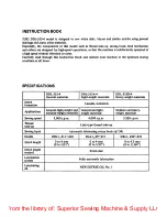
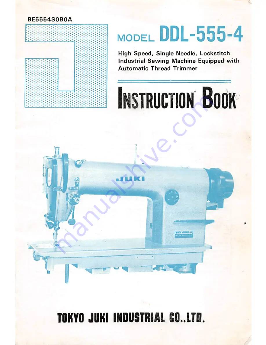
background image

From the library of: Superior Sewing Machine & Supply LLC

Summary of Contents for DDL-555-4

Page 1: ... DDL 555 4 High Speed Single Needle Lockstitch Industrial Sewing Machine Equipped with Automatic Thread Trimmer Instruction Book nJ U Kl TOKYO JUKI INDUSTRIAL CO LTO From the library of Superior Sewing Machine Supply LLC ...

Page 2: ...CATIONS DDL 555 4 General materials DDL 555A 4 Light weight materials DDL 555H 4 Heavy weight materials Stitch formation 1 needle lockstitch Applications General light weight and medium weight materials General and light weight materials Medium and heavy weight materials Sewing speed S 000 s p m 4 000 s p m 3 500 s p m Thread take up Link type thread take up Sewing hpok Automatic lubricating rotar...

Page 3: ... reverse feedcontrol lever 19 HI ADJUSTMENT 20 1 Feed mechanism 20 2 Replacingthe sewinghook 22 3 Sewinghook position related to the needle 23 4 Heightof the presserbar 24 5 Thread take upaction 25 6 Returningpressureof the reverse feed control lever 25 7 Adjusting the needle stop position after thread trimming 26 8 Sharpening the counter knife 27 IV HOWTO ADJUST THE WIPER 28 1 Adjusting the posit...

Page 4: ...eservoir oi Rubber cushion j vf r reservoir Operator side Hinge side Install the oil reservoir in such a manner that it is supported by the 4 corners of an opening in the table 1 Nail in the 2 felt pads of 4 mm 5 32 thick to the 2 corners near the operator 2 Nail in the 2 felt pads of 6 mm 15 64 thick to the remaining 2 corners hinged side 3 Place the oil reservoir on the felt pads 4 Insert the ru...

Page 5: ... 820 4 540 90 MTS P00850A0 3 610 4 320 85 MTS P00800A0 3 390 4 000 80 MTS P00750A0 3 160 3 790 42 MTJ VM004200 75 MTS P00700A0 2 950 3 520 70 MTS P00650A0 2 740 3 260 Note The center hole on the motor pulley is tapered and the normal pulleys commercially avail able in the market can not be used for these machines If the belt is too long the connecting rod may not work smoothly How to install the p...

Page 6: ...ting bar adjust the vertical position of the connect ing bar by sliding the connecting bar positioner Connecting bar posi tioner 2 How to adjust the pedal angle You can adjust the pedal angle by changing the effective length of the connecting bar Loosen the clamp screw and change the effec tive length of the connecting bar 3 From the library of Superior Sewing Machine Supply LLC ...

Page 7: ...he hand wheel side and fix it with a lock nut Fix the cord onto the support rod by means of the nylon clamper so that it does not contact with the V belt HITACHI motors Be careful not to allow the rotor and the stater to contact with each other The clearance between the printed circuit board cover and the rotor magnet is 0 S to 1 5 mm Pass the cord through the inside of the synchronizer cover and ...

Page 8: ... the selector switch for controlling the count back stitching with 3 pole con nector for HITACHI 6 pole connector for MATSUSHITA 5 is the cord to the wiperand the control lever for switch backstitching with 6 poleconnector Pass the cord through the opposite side of the motor pulley via the hook beneath the table and plug in 6 is the cord for driving the thread trimmer solenoid and the automatic re...

Page 9: ...US0 200 17 2e8C H n i034 60 200 Ij6 34S0 G imsusTO Eiicwic rcusTittL cajjo JUKI JUKB I Clieck your operating voltage with the rated voltage Hz and phase specified by the machine plate of each motor If the motor is operated with a different voltage not only the motor itself but also the control circuits may be broken please note 6 V From the library of Superior Sewing Machine Supply LLC ...

Page 10: ...ch belt coverframe A D to the arm One of the tappedholesisjointly usedfor attach ing a cord holder 4 Attach bobbin winder thread tension post assembly to belt cover frame B D and insert them intb belt cover frame A D 5 Put bobbin winder D into belt cover frame A 6 Attach belt cover panel 6 to belt cover frame A 7 Fix belt cover frame B to the table top by screwing2 wood screwsinto guide holes and ...

Page 11: ...ate the machine at a higher speed depending on the necessity of sewing works and operator s ability after the first 1 montli has passed o Keep away from the needle dropping place when you switch the machine on o Do not fail to switch off the machine before you tilt the machine head backwards for lubrica tion or cleaning or removing the V belt If you mistakenly tread on the pedal the motor puUeywil...

Page 12: ...ew the oil It can be drained by removing the oil drain cap screw 2 In order to thoroughly lubricate the machine provide it with an idle run for about 10 minutes at a sewing speed of 3 000 to 3 500 s p m before using a newly installed machine or a machine which has not been operated for a long period of time 2 Lubrication and amount of oil HIGH mark Oil reservoir LOW mark Before driving the machine...

Page 13: ... far side of the crank Note After this adjustment let the machine run and confirm the result of adjustment Oil regulating valve Adjustment of oil amount fed to the sewing hook Adjust it by means of the oil adjusting screw which is located on the hook driving shaft from bushing Amount of flowing oil is increased by turning clockwise and decreased by turning counterclockwise More 3 Checking the peda...

Page 14: ...ck the pedal to the neutral position immediately after the machine has started to perform the thread trimming action The thread trimming action is automatically completed and you do not needto keepthe pedal at the thread trimming position any longer o When the machinestops the needle will be held at the lower position o When you want to bringup the needle thread on the pedalfullybackwards heel dow...

Page 15: ...he left Adjustment of the backward pressure HITACHI motor The backward pressure can be adjusted by means of the adjustment nut of the backward pressure spring The pressure is increased by tightening the spring and reduced by loosening Adjustment of the pedal stroke The pedal stroke can be adjusted by changing the connection of the upper connecting rod with the motor regulating lever HITACHI motor ...

Page 16: ... to automatically trim off the thread immedi ately by treading on the pedal backwards before or after forming the count back stitch at the start of a seam line Even tiiough you tread on the pedal for thread trimming while the count back stitch is being formed the thread trimming action will not be performed prior to the forma tion of the said count back stitch When the selector switch for End is t...

Page 17: ...ead on the pedal backwards for performing an idle thread trimming before passing the needle thread Then the needle will go up and stay at the highest position o Pass the needle thread in the order from to as shown in the illustration I 14 From the library of Superior Sewing Machine Supply LLC ...

Page 18: ...belt 3 Adjust the winding adjustment screw so that the thread is wound round the bobbin for about 80 per cent of its capacity 4 When the bobbin is wound unevenly correct it by moving the thread tension post bracket Tighten the screw for increasing the thread length to be wound and loosen for reduce 5 As soon as the bobbin in filled the bobbin winder will automatically stop Note In order not to wou...

Page 19: ...hread tension nut No 2 so that the needle and bobbin threads are inter looped in the middle of the material Do not excessively reduce the thread tension when sewing with a synthetic thread or the thread may be broken at the start of sewing Thread take up spring Adjust the thread take up spring for the follow ing standard Thread Thread No Stroke Tension Cotton 40 or less 7 to 10 mm 9 32 to 25 64 20...

Page 20: ...ead tension can be adjusted by tightening or loosening the tension screw of the bobbin case Turn the screw clockwise for increasing and counterclockwise for reducing the bobbin thread tension Use a proper size of DB 1 or DAxl needle according to the material as listed below thickness and type of thread and Needle Thread Material Cotlon Synthetic DB X 1 9 80 80 Fine Georgette nylon tetron broadclot...

Page 21: ...sser spring regulator in the clockwise direction and vice versa It is advisable to set it to about 5 Kg when general cloth is sewn Tighten the lock nut after adjusting the presser spring regulator Presser lifter Turn the hand lifting lever located in the rear of the machine head either to left or right and the presser foot will go up for about 5 mm 13 64 from the throat plate surface Push down han...

Page 22: ... the machine arm The ma ximum stitch length is 4 mm 5 32 13 Reverse stitching by using the reverse feed control lever N I Feed control lever OOL SBS 4 Push down the reverse feed control lever as long as a desired reverse stitch is completed Release your hand from the lever and it will immediately go up to feed the material in the forward direction 19 From the library of Superior Sewing Machine Sup...

Page 23: ...ighten 2 setscrews Needle mm mm Throat plate Feed dog If it is preferable to provide the feed mecha nism with an earlier timing than the standard timing in order to prevent the work from slip ping during stitching move the feed drive eccentric cam in the direction shown by the arrow Needle Throat plate Feed dog If it is necessary to delay the timing of feed mechanism in order to improve the thread...

Page 24: ... the feed bar shaft and turn 90 in either direction The front top of the feed dog will be raised to the highest position when the shaft is turned 90 in the direction shown by an arrow and vice versa Note The height of the feed dog must be corrected every time after changing its inclination Adjusting the feed dog height The standard height of the feed dog is to Jut out its teeth 0 8 mm 1 32 above t...

Page 25: ... Remove the bobbin case and the needle 3 Loosen the setscrew of the bobbin case holder positioning finger and remove the positioning finger 4 Loosen 2 sewing hook screws 5 Manually rotate the handwheel until the feed bar reaches its highest position 6 Rotate the sewing hook by your finger and hold it in the position as illustrated 7 Pull out the sewing hook to the left When installing the sewing h...

Page 26: ...lign the upper engraved line of the needle bar with the bottom end of the needle bar lower bushing Tighten the needle bar connection screw Sewing hook position 5 Loosen 2 setscrews to release the sewing hook 6 Mold by hand the sewing hook in the thread taking up position 7 Rotate the handwheel until the lower engraved line of the needle bar reaches the bottom end of the needle bar lower bushing 8 ...

Page 27: ...ar height How to use the pressure reducer It is possible to sliglitly reduce the pressure applied by the presser foot when the pressure reducer is used This system is quite useful when a floating presser foot is used or a work has to be turned round at an end of a seam to continue to stitch in a different direction Loosen the lock nut g and properly tighten the adjusting screw g and the presser fo...

Page 28: ...the thread take up lever by positioning the thread guide A in the middle or higher place This adjustment can be made after loosening the setscrew of the thread guide A 6 Returning pressure of the reverse feed control lever In order to allow the reverse feed control lever to immediately return to its stanby position after being released in any sewing conditions the lever is forced back by a strong ...

Page 29: ...ing element of the synchronizer component Refer to the separate Instruction Book prepared for the motor assembly for the details of adjustment HITACHI motor Remove the cover from the synchronizer component and adjust the installation angle of the printed circuit board within the adjust able range of the oval holes on the stater flange White Red dot Printed circuit board cover Stater flange Magneti...

Page 30: ... the counter knife immediately Put the resharpened counter knife back to it s correct position shown by the following illustration If you move the installing position of the counter knife to the right from the standard position the length of thread remaining on the needle after trimming becomes longer and vice versa I omm Bottom face of the throat plate Stepped part of the bed Counter knife Longer...

Page 31: ... the parallel clearance between the needle center and the straight inside face of the wiper becomes 1 mm Fix the wiper at such a position by tightening the lock nut 3 2 Adjust the position of the wiper magnet Pull the plunger fully into the coil loosen the screw 0 which is clamping the wiper magnet and adjust the position of the wiper magnet so that the wiper tip is positioned with a clearance of ...

Page 32: ...uitable height for your operation Loosen the screw 2 move the switch lever ij f up and down and obtain a suitable height DK Tighten the screw firmlyafter adjustment 3 Adjusting the reverse stitch length An excessive length of reverse stitch is usually formed by the operator until he gets used to operate this new device In such a case it would be advisable to shorten the seam line with the reverse ...

Page 33: ... the knee switch to drive the solenoid 4 You can adjust the stroke of the presser foot by rotating the plunger on the far side of the solenoid the stroke is increased by a clockwise turn and is decreased by a counterlockwise turn The maximum stroke performed by the presser foot is about 8 mm 5 16 5 Raise stopper A until it hits the oil re servoir by activating the solenoid 6 Raise the stopper A by...

Page 34: ...ess does not o Insert the needle in the cor 17 face to the correct direction rect way 2 Stitch 1 Distance from the sewing o Correct the clearance and 23 skipping hook blade from the needle timing of the sewing hook is not correct related to the needle 2 Needle bar height is not o Align the engraved line of the 23 correct needle bar with the bottom end of the needle bar lower bushing 3 Needle is be...

Page 35: ...a smaller thread guide S Idle 1 Inclination of the feed dog o Raise the front part of the 21 stitching is not proper feed dog front up position 2 Presser foot is not suitable o Refer to the above 3 5 3 Position of the feed dog is o Move the feed dog closer to the not proper operator 4 Thread tensions are not o Reduce the thread tensions 16 proper 6 Loose 1 Needle thread tension is o Increase the n...

Page 36: ...too great a small needle slot 9 Tension of the thread take up o Reduce the tension of the 16 spring is too high thread take up spring 8 Slipping 1 Presser foot does not give a o Increase the pressure of the 18 of cloths sufficient pressure to the presser bar cloths 2 Inclination of the feed dog is o Raise up the front part of the 21 not suitable feed dog front up position 3 Feed timing is too late...

Page 37: ... guide A on the arm is not properly positioned 7 Bobbin docs not smoothly spin in the bobbin case o Reduce the stroke and increase the tension of the take up spring o Move the thread guide A up wards o Replace it with an aluminium bobbin 16 25 34 y From the library of Superior Sewing Machine Supply LLC ...

Page 38: ... WP 0871602 SE x2 WS 08614I0 KR x2 SM 9082023 SE x2 88102 552 000 D8203 555 B00 88104 552 000 x2 D7114 555 BAB 88126 552 SM 9082023 SE WP 0871602 SE WS 0861410 KR 1 NM 6080721 SE 08113 555 800 x2 D8II4 555 80E SM 9082023 SE WP 0871602 SE WS 0861410 KR MM 6080721 SE 35 08115 555 800 SK 3514000 SDx4 B8105 552 000 D8112 555 80E SM 9061203 SE x3 WP 0671016 SE x3 WS 0621210 KR x3 88111 552 000 88107 55...

Page 39: ... STOPPER INSTALLING POSITION LifU 525J LEG INSTALLING POSlTiON 2 t 80 il s 3 6 S holetl H 100 Cf t X 35 as Ihoio sLTzfoi is 1 POWER SOURCE SWITCH installing POSITION jiTTfTr 76 tl5 90 rSoH 18 Ihol il fzio LEG INSTALLING POSITION From the library of Superior Sewing Machine Supply LLC ...

Page 40: ...ead Office Plant 2 1 8 chome Kokuryo cho Chofu shi Tokyo Japan Business Office 23 3 Kabuki cho 1 chome Shinjuku ku Tokyo 16Q Japan Cable JUKI TOKYO Telex 22967 232 2301 ip I hfedinTapan T From the library of Superior Sewing Machine Supply LLC ...

Reviews: