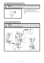
background image

ENGLISH

INStructIoN MaNuaL

DDL-8700a-7

Summary of Contents for DDL-8700A-7

Page 1: ... ENGLISH Instruction Manual DDL 8700A 7 ...

Page 2: ...chine head 13 17 Thread tension 14 18 Thread take up spring 14 19 Adjusting the thread take up stroke 14 20 Needle to hook relationship 15 21 Height of the feed dog 15 22 Tilt of the feed dog 16 23 Adjusting the feed timing 16 24 Cunter knife 17 25 Pedal pressure and pedal stroke 17 26 Adjustment of the pedal 18 FOR THE OPERATOR 19 1 Operating procedure of the sewing machine 19 2 Built in panel of...

Page 3: ...e rear cover 46 14 Connection of the pedal of standing work machine 48 15 External input output connector 48 16 Connection of the material end sensor 49 17 Initialization of the setting data 50 MAINTENANCE 51 1 Replacing the fuse 51 2 Adjusting the machine head 52 3 Connector layout drawing 53 4 Error codes 54 ...

Page 4: ...at the time of shipping AS 7 4 000sti min AH 7 3 500sti min 1 Needle used depends on the destination SPECIFICATIONS Supply voltage Single phase 100 to 120V 3 phase 200 to 240V Single phase 220 to 240V Frequency 50Hz 60Hz 50Hz 60Hz 50Hz 60Hz Operating environ ment Temperature 5 to 35 C Humidity 35 85 or less Temperature 5 to 35 C Humidity 35 85 or less Temperature 5 to 35 C Humidity 35 85 or less I...

Page 5: ... DRAWING OF TABLE bottom surface depth 20 2 ø3 4 bottom surface depth 10 depth 10 Hinge side only ...

Page 6: ... side B hinged side using a rubber based adhesive Then place under cover 4 on the fixed seats SET UP 1 1 3 3 8 1 2 4 3 A B 1 2 4 3 A B Needle bar side 0 7 8 7 6 9 2 1 5 Fit knee lifter pressing rod 6 Fit hinge 7 into the opening in the machine bed and fit the machine head to table rubber hinge 8 before placing the machine head on cushions 9 on the four corners 6 Securely attach head support rod 0 ...

Page 7: ... of the power switch Bundle the cord with cable clip band 3 to secure it Caution Do not insert the power plug into the plug receptacle 2 3 WARNING To protect against personal injury resulting from abrupt start of the sewing machine be sure to turn the power OFF unplug the machine and wait for five minutes or more before installing the pedal sensor To prevent damage of device caused by maloperation...

Page 8: ...ng the screws at the specified loca tions 4 Close the power switch cover Tighten screw 1 on the side face of the power switch cover 5 Firstly attach the staple supplied with the unit as accessories to the cable Then hammer them into the sewing machine table At this time attach the staples at the locations shown in the figure Staples large Cable draw out hole Pedal sensor Staples small Green Yellow...

Page 9: ...n and decreases as you turn the screw out Caution 1 If the screw is excessively loosened the spring will come off Loosen the screw to such an extent that the top of the screw can be ob served from the case 2 Whenever you have adjusted the screw be sure to secure the screw by tightening metal nut 5 to prevent the screw from loosening WARNING To protect against possible personal injury due to abrupt...

Page 10: ...rection of B Increase 5 Winding the bobbin thread 6 In case that the bobbin thread is not wound evenly on the bobbin remove the handwheel loosen screw 5 and adjust the height of bobbin thread tension 8 It is the standard that the center of the bobbin is as high as the center of thread tension disk 6 Adjust the position of thread tension disk 6 to the direction of D when the winding amount of the b...

Page 11: ...needle bar 2 in its lowest position does not hit presser foot 3 1 2 3 WARNING Be sure to turn the power OFF before the following work in order to prevent personal injury due to unintentional starting of the sewing machine 6 Adjusting the height of the knee lifter 7 Installing the thread stand 2 1 1 Assemble the thread stand unit and insert it in the hole in the machine table 2 Tighten nut 1 3 For ...

Page 12: ...parts of your body 3 If oil is mistakenly swallowed diarrhea or vomitting may occur Put oil in a place where children cannot reach 8 Lubrication 1 Amount of oil oil splashes confirmation paper 2 Position to confirm the amount of oil oil splashes Closely fit the paper against the wall surface of the bed Oil splashes confirmation paper 3 10 mm 25 mm 70 mm When carrying out the procedure described be...

Page 13: ...oximately 30 seconds to check the amount of oil in the hook A B 2 Adjusting the amount of oil oil spots in the hook 3 Sample showing the appropriate amount of oil in the hook mm Splashes of oil from the hook 1 Amount of oil oil splashes confirmation paper 2 Position to confirm the amount of oil oil splashes Oil splashes confirmation paper 25 mm 70 mm 4 Confirmation of the amount of oil supplied to...

Page 14: ...for the machine Use the proper needle in accordance with the thickness of thread used and the kinds of the materials 1 Turn the handwheel until the needle bar reaches the highest point of its stroke 2 Loosen screw 2 and hold needle 1 with its indented part A facing exactly to the right in direction B 3 Insert the needle fully into the hole in the needle bar in the direction of the arrow until the ...

Page 15: ...s in millimeters 1 Turn stitch length dial 1 in the direction of the arrow and align the desired number to marker dot A on the machine arm 1 Loosen nut 2 As you turn presser spring regu lator 1 clockwise in direction A the presser foot pressure will be increased 2 As you turn the presser spring regulator counter clockwise in direction B the pressure will be decreased 3 After adjustment tighten nut...

Page 16: ...e height of the presser bar 16 Threading the machine head WARNING Be sure to turn the power OFF before the following work in order to prevent personal injury due to unintentional starting of the sewing machine WARNING Be sure to turn the power OFF before the following work in order to prevent personal injury due to unintentional starting of the sewing machine ...

Page 17: ...ulled out by the thread take up 3 Normally thread guide 1 is positioned in a way that marker line C is aligned with the center of the screw 1 C B A 1 Adjusting the needle thread tension 1 The length of thread remaining at the needle tip after thread trimming is shortened by turn ing tension regulating nut No 1 1 clockwise in direction A 2 It is lengthened by turning the nut counterclock wise in di...

Page 18: ...e bar height 2 For a DB needle Align marker line A on needle bar 2 with the bottom end of needle bar lower bushing 3 then tighten setscrew 1 For a DA needle Align marker line C on needle bar 2 with the bottom end of needle bar lower bushing 3 then tighten setscrew 1 Adjusting position of the hook a 3 For a DB needle Loosen the three hook setscrews turn the handwheel and align marker line B on asce...

Page 19: ...he feed bar shaft is aligned with marker dot B on feed rocker 1 2 To tilt the feed dog with its front up in order to prevent puckering loosen the setscrew and turn the feed bar shaft 90 in the direction of the arrow using a screwdriver 3 To tilt the feed dog with its front down in order to prevent uneven material feed turn the feed bar shaft 90 in the opposite direction from the arrow Whenever the...

Page 20: ...the front part of the pedal When the pedal pressure spring 1 is hooked to the lower side the pedal pressure will decrease and when hooked to the upper side the pedal pressure will increase 2 Adjusting the pressure required to de press the back part of the pedal The pressure increases as you turn reverse de pressing regulator screw 2 in and decreases as you turn the screw out 3 Adjusting the pedal ...

Page 21: ...traightened 2 Adjusting the pedal angle 1 The pedal tilt can be freely adjusted by changing the length of the connecting rod 2 Loosen adjust screw 4 and adjust the length of connecting rod 2 26 Adjustment of the pedal WARNING Be sure to turn the power OFF before the following work in order to prevent personal injury due to unintentional starting of the sewing machine ...

Page 22: ...e machine stops with its needle up or down when you reset the pedal to its original position d The machine trims threads when you fully depress the back part of the pedal 5 When the auto lifer AK device is used one more operating switch is provided between the sewing machine stop switch and thread trimming switch The presser foot goes up when you lightly depress the back part of the pedal 4 and if...

Page 23: ...e case the machine is not used for a long time remove the power plug from the plug receptacle 5 For some types of the sewing machine heads reverse feed is performed by pressing touch back switch 7 4 Reverse feed stitching at the beginning of sew ing reverse feed stitching at the end of sewing and various sewing patterns can be set on built in panel 6 of the machine head ...

Page 24: ...and off 5 switch Used for changing the content of the selected display flashing section and for changing over effective ineffective of the reverse stitch at sewing end 6 switch Used for changing the content of the selected display flashing section 7 switch It is used to call the production support function and to call the one touch setting it should be held pressed for one second Indicators A and ...

Page 25: ...to be changed by using switch 4 The number which is flashing on and off repre sents the process which is being set Change the number of stitches for the selected process by using switch 5 and switch 6 Press switch 3 to confirm the change you have made The number of stitches that can be set is 0 to 15 Caution The sewing machine cannot perform sew ing when the display of the number of stitches for a...

Page 26: ...n can be changed over by pressing switch 2 When the overlapped stitching pattern is ren dered effective LED D lights up 2 Select a process A B C or D the number of stitches for which is to be changed by using switch 4 The number which is flashing on and off repre sents the process which is being set 3 Change the number of stitches for the selected process by using switch 5 and switch 6 4 Press swi...

Page 27: ...f revolution is the value which is set for setting No 38 4 Setting of the max speed of stitch The highest speed of stitch of the machine head is set The upper limit of the set value differs with the type of machine head to which the SC is connected Setting range 150 Max value sti min 5 Material end sensor function Material end sensor function is ineffective Once the material end is detected the se...

Page 28: ...ity rate display mode F300 Pitch time display mode F400 Average number of revolutions display mode F500 Sewing machine availability status is automatically measured and displayed on the control panel The data obtained can be used as basic data to perform process analyses line arrangement and equipment efficiency checkup Bobbin counter function Bobbin counter display mode In order to change bobbins...

Page 29: ...e table Mode resetting operation for the resetting procedure of data 7 To return to the normal sewing state press switch 7 Data to be displayed under the respective modes are as described in the table below Table 1 Display of modes Mode name Indicator A Indicator B Indicator B when switch 5 is pressed Target No of pcs display mode F100 Actual number of pieces Unit piece 1 Target number of pieces U...

Page 30: ...g machine Resets average availability rate of sewing machine Resets average pitch time Resets average number of revolutions of sewing machine Bobbin counter display mode Resets the bobbin counter value Note that only the bobbin counter is immediately reset by pressing switch 5 Detailed setting of production volume management function F101 F102 When switch 7 is held pressed for three sec onds under...

Page 31: ...g No is moved forward or backward the previous or subsequent content of the setting is confirmed Be careful when the content of a setting is changed when the switch is touched Example Changing the maximum number of revolu tions setting No 96 Press switch 3 or switch 4 to call set ting No 96 The current set value is displayed on indicator B Press switch 5 to change the setting to 2500 The content o...

Page 32: ... 3 7 0 8 Number of rotation of reverse feed stitching Sewing speed of reverse feed stitching 150 to 3 000 sti min 8 1 9 0 0 9 Thread trimming prohibiting function Thread trimming prohibiting function 0 Thread trimming is effective 1 Thread trimming is prohibited Output of solenoid is prohibited Thread trimmer and wiper 0 1 9 0 33 10 Setting of needle bar stop position when the sewing machine stops...

Page 33: ...y machine head 100 to MAX sti min 3 7 8 0 0 33 38 One shot speed One shot speed The max value depends on the number of ro tation of the sewing machine head 150 to MAX sti min 3 8 2 5 0 0 38 39 Pedal stroke at the start of rotation Position where the sewing machine starts rotating from pedal neutral position Pedal stroke 10 to 50 0 1 mm 3 9 3 0 40 Low speed section of pedal Position where the sewin...

Page 34: ...verse feed stitching at the start of sewing This function can specify the sewing speed of reverse feed stitching at the start of sewing 0 The speed will depend on the manual operation by pedal etc 1 The speed will depend on the specified reverse feed stitching speed No 8 0 1 5 9 1 40 60 Function of stop immediately after reverse feed stitching at the start of sewing Function at the time of complet...

Page 35: ...initial value of the machine head 9 5 8 7 A S 96 Max number of rotation setting Max number of rotation of the sewing machine head can be set The MAX value differs by machine head 150 to MAX sti min 9 6 4 0 0 0 42 100 Number of stitches sewn before thread clamp works at the beginning of sewing Sets the number of stitches to be sewn at the beginning of sew ing before the thread clamp solenoid CN36 7...

Page 36: ...ubtracts from the predetermined value and indicates the used amount of bobbin thread For the details refer to the instruction manual for the control panel 0 Bobbin thread counting function is not operative 1 Bobbin thread counting function is operative Caution If 0 is set the LCD indication on the control panel will go out and the bobbin thread count ing function will be invalid 5 Thread trimming ...

Page 37: ...le To assign the thread trimming function to the input function setting connector indication number i01 CN36 4 1 Select function setting No 12 with the operating procedure of function setting procedures 1 through 3 2 Select the item of in with keys 5 and 6 3 Select the port of the indication number i01 by means of key 4 4 Select the thread trimming function TSW with keys 5 and 6 5 Determine the th...

Page 38: ...ited 11 TinH Function of prohibiting thread trimming output Output of thread trimming is prohibited 12 LSSW Low speed command input This function works as low speed switch for standing sewing machine 13 HSSW High speed command input This function works as high speed switch for standing sewing machine 14 USW Needle lifting function UP stop motion is performed when switch is pressed dur ing DOWN sto...

Page 39: ...output Revolution demanding command state is output 13 TSWo Tsw command monitor output Thread trimming command status is output Input function setting connectors Output function setting connector Connector No Pin No Display No Initial value of function setting CN36 4 i01 noP No function setting CN54 3 i02 noP No function setting CN50 12 i03 SoFT Soft start speed limit input CN36 5 i04 bT Reverse f...

Page 40: ...at the second neutral position after it has come off the neutral position once 0 off Function of neutral automatic presser lifting is not operative 1 on Selection of function of neutral automatic presser lifting 1 Needle up down switch function changeover function Function setting No 22 The needle up down switch function can be changed over between the needle up down compensation and one stitch co...

Page 41: ...f depressing front part of the pedal automatic thread trimming is performed after reverse feed stitching as many as the number of stitches specified by the function setting No 31 has been performed 5 1 1 1 When operating touch back switch at the time of either stop of the sewing ma chine or depressing front part of the pedal automatic thread trimming is per formed after reverse feed stitching as m...

Page 42: ...e feed stitching at the start of sewing Function setting No 51 On timing of solenoid for reverse feed stitching at the start of sewing can be compensated by the unit of angle Adjusting range 36 to 36 1 10 2 Compensation of off timing of solenoid for reverse feed stitching at the start of sewing Function setting No 52 Off timing of solenoid for reverse feed stitching at the start of sewing can be c...

Page 43: ...is not provided Presser foot does not automatically go up after thread trimming 1 on Function of automatically lifting the presser foot is provided Presser foot automatically goes up after thread trimming 8 Reverse revolution to lift the needle after thread trimming Function setting No 56 This function is used to make the sewing machine rotate in the reverse direction after thread trimming to lift...

Page 44: ... at the time of completion of reverse feed stitching at the start of sewing Normal use depending on the pedal condition Speed is accelerated to the highest without a break This function is used when temporary stop is used properly Cuff and cuff attaching 0 Speed is not reduced 1 Speed is reduced Sew without stopping without a break Temporary stop 4 9 4 1 0 7 0 0 9 2 0 7 3 1 6 Function of pedal cur...

Page 45: ...Setting range 60 to 60 1 3 UP position starting angle compensation Function setting No 121 Angle to detect UP position starting is compensated Setting range 15 to 15 1 4 DOWN position starting angle compensation Function setting No 122 Angle to detect DOWN position starting is compensated Setting range 15 to 15 1 9 Continuous stitching one shot stitching nonstop function Function setting No 94 Thi...

Page 46: ... displayed 2 If any display 0 or 8 other than a numeric value appears on indicator B refer to the Engineer s Manual 3 Turn OFF the power switch and turn ON the power switch again to return to the normal mode Caution Be sure to re turn ON the power switch when one or more seconds have passed after turning it OFF If the ON OFF oper ation is carried out faster than the above the setting may not chang...

Page 47: ...resser foot is not automatically lifted when pro grammed stitching is completed Solenoid drive display 33V Air drive display 24V Caution 1 To perform re turning ON of the power be sure to perform after the time of one second or more has passed If ON OFF operation of the power is performed quickly setting may be not changed over well 2 Auto lifter is not actuated unless this function is properly se...

Page 48: ...played when turning the power ON and the key lock function is rendered ineffective KEY LOCK display when turning the power ON Display appears The key lock function is effective Display does not appear The key lock function is ineffective In the case the operation is disabled Setting of the number of stitches for a pattern 4 Functions that are operated in the same pro cedure as in the case of norma...

Page 49: ... blown out of the fuse 1 Press the OFF button of the power switch to turn OFF the power after confirming that the sewing machine has stopped 2 Draw out the power cord coming from the power plug socket after confirming that the power switch is turned OFF Perform the work of step 3 after confirming that the power has been cut and it has passed for 5 minutes or more 1 1 Panel PWB Front cover 2 3 Remo...

Page 50: ... 47 5 Remove two screws 3 from the lower part of the rear cover 6 Remove screw 4 from the rear face of the rear cover 7 Move the rear cover backward and carefully tilt it 3 4 ...

Page 51: ... name Input output Description Electric spec 1 5V Power source 2 MA Output Rotation signal 360 pulses rotation DC5V 3 MB Output DC5V 4 UDET N Output L is output when needle bar is at LOW position DC5V 5 DDET N Output L is output when needle bar is at UP position DC5V 6 HS N Output Rotation signal 45 pulses rotation DC5V 7 BTD N Output L is output when the back tack solenoid works DC5V 8 TRMD N Out...

Page 52: ...etection of the material end 0 Automatic thread trimming is not carried out 1 Automatic thread trimming is carried out The number of stitches after the activation of the material end sensor function setting No 4 The number of stitches to be sewn until the sew ing machine stops after the material end sensor has detected the material end can be specified Data setting range 0 19 1 stitch One shot fun...

Page 53: ...ont cover The machine returns to the normal motion Caution 1 When you carry out the aforementioned operation the neutral position correction value for the pedal sensor is also initialized It is therefore necessary to carry out automatic correc tion of the pedal sensor neutral position before using the sewing machine Refer 9 Au tomatic compensation of neutral point of the pedal sensor p 43 2 When y...

Page 54: ...rom the plug receptacle 3 Open the cover refer ring to 13 Remov ing the rear cover p 46 4 Remove fuses 1 and 2 by holding their glass section Caution This work poses a risk of electric shock Be sure to remove the fuses after LED 3 has com pletely gone out 5 Use the fuse which has the specified fuse capacity 1 3 15 A 250 V Time lag fuse 2 6 3 A 250 V Time lag fuse Part number KF000000080 Part numbe...

Page 55: ... in the indicator and the mode is changed over to the adjustment mode 3 Turn the pulley of the machine head by hand until the main shaft reference signal is detected At this time the degree of an angle from the main shaft reference signal is displayed on the indicator B The value is the reference value 4 In this state align the white dot 7 of the hand wheel with the concave 8 of the pulley cover a...

Page 56: ...e 8 Panel cable 9 Power cord WARNING To protect against personal injury resulting from abrupt start of the sewing machine be sure to turn the power OFF unplug the machine and wait for five minutes or more before connecting the connectors To prevent damage of device caused by maloperation and wrong specifications be sure to connect all the corresponding connectors to the specified places If any of ...

Page 57: ...d Neutral position may be shifted when changing spring pressure of the pedal or the like Execute the automatic neutral correc tion function of the pedal sensor The sewing machine does not stop even when the pedal is returned to its neutral position Presser foot does not go up even when auto lifter device is attached Auto lifter function is OFF Select FL ON by auto lifter function selection Pedal s...

Page 58: ... belt tension E071 Disconnection of motor out put connector Disconnection of motor connector Check the motor output connector for loose connection and disconnection E072 Overload of motor at the time of thread trimming motion Same as E007 Same as E007 E079 Automatic operation over load error Not used Not used E220 Grease up warning When the predetermined number of stitches has been reached Repleni...

Page 59: ...ing to the default values referring to Initializing the function setting data in the Engineer s Man ual E704 Data fault The stored data have broken Reset all data on the function setting to the default values referring to Initializing the function setting data in the Engineer s Man ual E730 Encoder failure When the motor signal is not properly in putted Check the motor signal connector CN30 for lo...

Page 60: ...broken E815 Regeneration resistor is not connected CN11 Not connected Check whether the generation resister is connected to CN11 E906 Operation panel transmis sion failure Disconnection of operation panel cord Operation panel has broken Check the operation panel connector CN38 for loose connection and disconnection Check whether the operation panel cord has broken since the cord is caught in the m...

Reviews: