


Copyright © 2012-2013 JUKI CORPORATION
• All rights reserved throughout the world.
Please do not hesitate to contact our distributors or agents in your area for further information when necessary.
*
The description covered in this instruction manual is subject to change for improvement of the
commodity without notice.
13 · 09 Printed in Japan
SEWING MACHINERY BUSINESS UNIT
2-11-1, TSURUMAKI, TAMA-SHI,
TOKYO, 206-8551, JAPAN
PHONE : (81)42-357-2371
FAX : (81)42-357-2274
http://www.juki.com
No.02
40092228
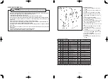
INSTRUCTION MANUAL
DSC-245,-4,-7
DSC-245V,-4,-7
NOTE :
Read safety instructions carefully and understand them before using.
Retain this Instruction Manual for future reference.
Summary of Contents for DSC-245
Page 2: ...日本語 ...
Page 31: ...日本語 日本語 ...


