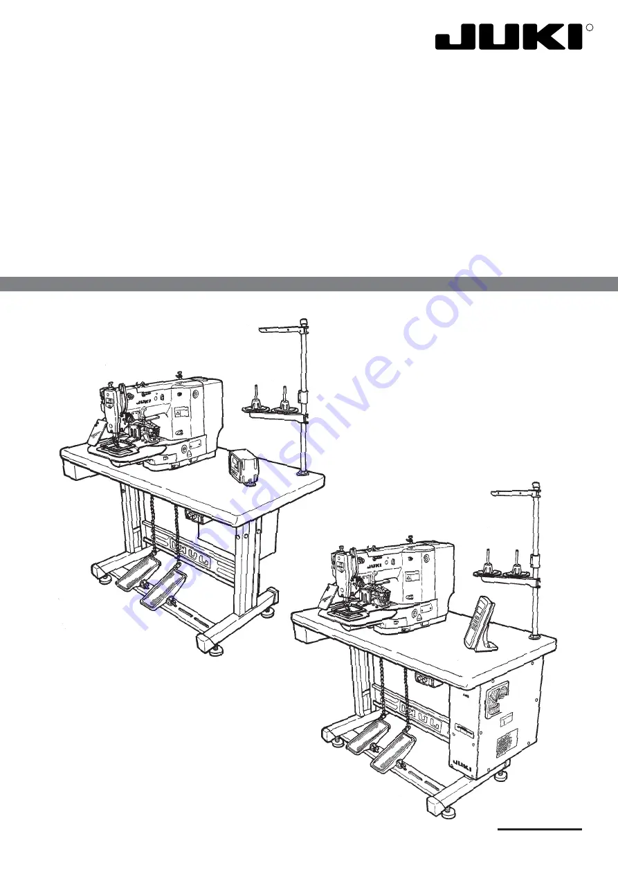
background image

29326600

No.E329-03

R

ENGINEER’S MANUAL

Computer-controlled High Speed
Bar Tacking Industrial Sewing Machine

LK-1910 / LK-1920

Computer-controlled High Speed Bar Tacking
Industrial Sewing Machine with Input Function

LK-1930

Summary of Contents for LK-1910

Page 1: ...o E329 03 R ENGINEER S MANUAL Computer controlled High Speed Bar Tacking Industrial Sewing Machine LK 1910 LK 1920 Computer controlled High Speed Bar Tacking Industrial Sewing Machine with Input Function LK 1930 ...

Page 2: ...edures Results of Improper Adjustment and other important information which are not covered in the Instruction Manual It is advisable to use the relevant Instruction Manual and Parts List together with this Engineer s Manual when carrying out the maintenance of these machines This manual gives the Standard Adjustment on the former page under which the most basic adjustment value is described and o...

Page 3: ...ustment of the thread trimmer mechanism components 17 1 Adjusting the thread trimmer cam 17 2 Adjusting the thread trimmer link stopper screw 17 3 Position of the thread trimmer shaft 19 4 Position of the cam installing link stopper 19 5 Position of the thread trimmer magnet arm 21 6 Position of the moving and counter knives 23 7 Height of the moving and counter knives 23 8 Inclination of the blad...

Page 4: ... the contents of the memory switches onto the floppy disk 59 7 DESCRIPTION OF THE MEMORY SWITCHES LK 1930 60 8 INITIALIZATION OF THE MEMORY SWITCH LK 1930 85 1 How to initialize 85 2 Table of the initial setting 86 9 COMPLEMENTARY EXPLANATION OF FUNCTION NOS LK 1930 90 1 Fixed retracted position setting Function No 003 90 2 How to use the bank function Function No 021 and 075 91 3 Combination func...

Page 5: ...40 V 147 2 Change of the voltage from 220 to 415 V 147 20 MAINTENANCE AND INSPECTION 148 1 Replacing the printed circuit boards 148 1 MAIN circuit board 148 2 SERVO circuit board 148 3 PMDC circuit board 148 4 POWER circuit board 149 21 TROUBLES AND CORRECTIVE MEASURES 150 1 Mechanical parts 150 2 With regard to sewing 152 3 Electrical parts Also refer to Block diagram 159 22 CURCUIT DIAGRAM 166 1...

Page 6: ... byte Allows a pattern to be enlarged or reduced on the X axis and Y axis independently when sewing a pattern Used to stop machine operation during a stitching cycle Used to detect needle thread breakage to automatically stop machine 1 to 99 patterns can be selected by specifying the desired pattern Nos In case of EEP ROM Tells the time to replace the bobbin by the bobbin thread counter Max 9 999 ...

Page 7: ...foot switch 2nd step Start switch Needle thread breakage detecting plate Wiper switch Temporary stop switch Intermediate presser for LK 1920 30 only Work clamp feet Manual pedal Not provided with pneumatic type Thread stand Operation box for LK 1930 only Control box for LK 1930 only Power switch Operation box for LK 1910 20 only Control box for LK 1910 20 only ...

Page 8: ...ding Set No Set value Set No Set value Set No Set value CP 1 CP 2 CP 3 CP 4 CP 5 Stop of bobbin thread winding Forward Backward key Addition or subtraction of the set value Addition or subtraction of the set value Addition or subtraction of the set value Addition or subtraction of the set value Addition or subtraction of the set value Feed forward or feed backward Addition or subtraction of the se...

Page 9: ... pattern X scale key Sets the value of the lateral direction Speed volume Y scale key Sets the value of the longitudinal direction Bobbin thread setting key Sets the value on the bobbin thread counter Error LED Lights up when an error occurs Thread winding key Used for the bobbin thread winding Needle threading key Makes easy to thread the needle Contrast volume Adjusts the light and shade of indi...

Page 10: ...arance provided between the counter weight and the main shaft front bushing is 0 5 mm 2 Installing the main motor 2 5 mm 0 1 0 5 mm 0 5mm 1 2 3 4 5 1 2 3 4 3 ADJUSTMENTS 1 Adjustment of the main shaft components Standard Adjustment Thread trimmer cam Machine arm Flat section ...

Page 11: ...otor 1 and the coupling 0 5 mm fit screw No 1 4 to the flat section Then install the motor 2 Insert rubber ring 3 RO1524240100 between main shaft rear bearing 2 and the coupling making the clearance between the main shaft rear bearing and the coupling 2 5 mm fit screws No 1 4 to the flat section Then install the motor Caution When engaging the respective couplings be sure to align the two position...

Page 12: ...Clearance provided between section C of the intermediate presser driving arm and section D of the machine arm boss is 0 5 0 2 mm in the state that the clearance becomes narrowest lower dead point of intermediate presser 3 Fit closely intermediate presser cam 1 and intermediate presser cam stopper 2 0 5 0 2 mm A B C D E F 1 2 3 1 2 3 Standard Adjustment Standard Adjustment 3 Adjusting the main shaf...

Page 13: ... presser is increased As a result maloperation or trouble will be caused If the main shaft sensor is not properly installed the sensor may be damaged or error may ocur 1 Turn the main shaft engraved dot A of the main shaft comes just above 2 Insert a thickness gauge of 0 5 mm between section C of the intermediate presser driving arm and section D of machine arm boss and make a state that section C...

Page 14: ...bracket support plate comes in close contact with the bottom face of intermediate presser guide bracket 2 3 Adjusting the position of the intermediate presser bar guide bracket 1 Protruding amount of intermediate presser bar 3 from intermediate presser bar guide bracket 2 is 12 5 mm 2 Needle passes the center of the intermediate presser 12 5 mm 1 2 1 2 3 4 5 A Standard Adjustment Close contact Clo...

Page 15: ...er bar guide bracket 2 is 12 5 mm and needle 4 passes the center of intermediate presser 5 Caution Keep the tightening torque of setscrew 1 at 390 to 490 N cm 40 to 50 kgf cm If section A does not come in close contact the intermediate presser bar guide bracket support plate is likely to be broken If the protruding amount of the intermediate presser bar is excessively large breakage of the interme...

Page 16: ... 11 24 5 mm 1 2 Standard Adjustment 4 Height of the intermediate presser adjusting screw Height of the intermediate presser adjusting screw is 24 5 mm for the standard adjustment value ...

Page 17: ...ermediate presser adjusting nut 2 2 When the height is increased the pressing pressure is decreased Caution 1 Adjust the height within the range of 24 5 to 40 mm 2 When using the intermediate presser stroke with the value larger than the standard adjustment value 4 mm be sure to set the height of the intermediate presser to the minimum 24 5 mm ...

Page 18: ... 8 mm A 1 2 3 4 5 6 A B 1 2 3 4 A B Align Parallel 1 m m o r m o r e Standard Adjustment Standard Adjustment 5 Adjusting the position of the intermediate presser solenoid 3 Adjusting the wiper components 1 Adjusting the position of the wiper ...

Page 19: ...pring retainer 1 protruding amount of plunger 3 from solenoid frame 4 becomes 15 to 16 mm 1 Determine the height of the wiper when the needle bar is at its upper stop position Loosen setscrew 1 in the wiper shaft cap and turn the wiper shaft cap so that the wiper comes almost below the needle Then temporarily tighten setscrew 1 2 Loosen setscrew 2 and adjust so that clearance provided between the ...

Page 20: ...onents 1 2 3 4 1 2 1 1 1 Standard Adjustment 1 Adjusting the longitudinal position of the oscillator 2 Adjusting the backlash of the oscillator gear 3 Removing the play of the shuttle driving shaft Shuttle drive shaft gear Face A 0 1 mm or less Face A ...

Page 21: ...ttle driver smoothly rotates 3 Tighten setscrews 1 Caution Be sure to keep the rotating direction shown in the figure when removing the backlash 1 Play in the axial direction of the shuttle driver shaft Loosen two thrust collar setscrews 1 and tighten them while pressing the shuttle driver shaft in the direction of arrow If the longitudinal position of the oscillator is not correct it will cause t...

Page 22: ... screw 1 Make sure that thread trimmer roller 2 has a clearance against the both end faces of the slit of thread trimmer cam 6 and smoothly enters the slt when pushing cam installing link 1 in the direction of arrow b in the approach run section in the range of A of the thread trimmer cam 1 2 3 1 2 3 4 5 6 A 3 Clearance0 5 mm 2 4 B 5 Adjustment of the thread trimmer mechanism components Standard A...

Page 23: ...nnecting bar 5 4 Pressing cam installing link 1 in the direction of arrow lightly fit thread trimmer roller 2 to the thread trimmer cam It does not enter the slit of the cam 5 Start tightening thread trimmer link stopper screw 4 The top end of thread trimmer link stopper screw 4 comes in contact with section B of thread trimmer connecting bar 5 and when tightening further cam installing link 1 tur...

Page 24: ... arm 1 is separated from tension release notch 3 thread trimmer stopper support comes in contact with the section B of the sewing machine arm stopper 4 Position of the cam installing link stopper 1 Clearances between notch A of the cam installing link and the cam installing link are 0 3 mm each in the state that the thread trimmer is separated thread trimmer stopper support comes in contact with t...

Page 25: ...installing link in the direction of arrow a Then removing the play tighten setscrew 6 in the cam installing link 1 In the state that the thread trimmer is separated loosen two setscrews 1 in the cam installing link stopper and adjust the respective clearances to 0 3 mm each Then tighten the setscrews 1 If thread trimmer shaft 4 is mitakenly adjusted the receiving amount of thread trimmer shaft4 be...

Page 26: ... Standard Adjustment 5 Position of the thread trimmer magnet arm 1 When thread trimmer magnet 3 draws the clearance between the roller attaching face of cam installing link 4 and the cam face of thread trimmer cam 2 is 1 mm ...

Page 27: ...osition of thread trimmer magnet arm 5 so that a clearance of 1 mm is provided between the cam face of thread trimmer cam 2 and the roller attaching face of cam installing link 4 Then tighten screw 1 Thread trimmer roller enters the slit of thread trimmer cam causing thread trimmer failure or sewing machine lock Returning to the initial position of the thread trimmer is delayed and release of the ...

Page 28: ...knife Engagement amount of the needle hole guide with the blade section of the moving knife is 0 15 mm Counter knife Level difference between the needle hole guide and the blade section of the counter knife is 0 1 mm to 0 15 mm 8 Inclination of the blade point of the counter knife In order to cut two threads needle thread and bobbin thread in uniformity the blade face of the counter knife is slant...

Page 29: ...crewdriver or the like When the clearance is 0 5 mm or less When the moving knife pulls threads blade point of the counter knife cuts the threads and needle bobbin threads are cut short When the clearance is 0 5 mm or more Length of the remaining thread under the cloth after thread trimming is lengthened If the level difference 0 25 to 0 3 mm between the moving knife and counter knife is small it ...

Page 30: ... 7 comes in contact with tension release link 8 adjust the clearance between the periphery of thread trimmer cam 6 and tension release arm pin 5 to 1 2 mm 3 Floating amount of the thread tension disk 2 3 4 1 2 3 4 5 6 Adjustment of the tension release components Standard Adjustment Thread tension disk Return spring Widen Tension release link Narrow Floating amount A Thread trimmer cam 1 2 To come ...

Page 31: ...e next item 3 1 Remove the arm cover and make sure that tension release pin 3 rides on tension release notch 4 2 If the pin does not ride on the notch push cam installing link 5 by hand in the e direction and rotate the main shaft in the normal direction to make the state shown in the figure 3 Under the state shown in the figure loosen setscrew 2 in the tension release adjusting arm Floating amoun...

Page 32: ... 27 1 Mechanical origin 2 Adjusting the Y origin sensor 195 mm 63 1 2 3 7 Adjusting the sensor components Standard Adjustment Needle hole X feed support shaft Y feed support shaft Feed plate ...

Page 33: ...cannot be secured Distortion of stitching shape will occur 1 Select Test mode No 2 Origin retrieval For LK 1910 20 only 2 Simultaneously pressing and in the operation panel turn ON the power For LK 1930 only 3 Press in the operation panel For LK 1930 only 4 Every time depressing the pedal the origin is retrieved Loosen sensor slit setscrew 1 and shift the position of Y sensor slit 2 to set the fee...

Page 34: ... 29 1 2 3 Standard Adjustment 3 Adjusting the X origin sensor ...

Page 35: ... ON the power For LK 1930 only 3 Press in the operation panel For LK 1930 only 4 Every time depressing the pedal the origin is retrieved Loosen sensor installing base setscrew 1 and shift the position of X sensor 2 to set the feed plate to the position of origin Caution After the adjustment make sure that X sensor slit 3 does not interfere with X sensor 2 Selection of model ...

Page 36: ...ed mechanism components 1 Adjusting the position of the X motor base 2 Adjusting the positions of the X motor and the Y motor adjusting the backlash of the driving gear Standard Adjustment Center of the hook driving shaft Center of the motor base ...

Page 37: ...enter of the hook driving shaft 1 Remove felt presser 3 and loosen four setscrews 1 Lightly push Y motor 4 in the direction of arrow a and tighten again setscrews 1 2 Loosen four setscrews 2 and lightly push X motor 5 in the direction of arrow a Then tighten again setscrews 2 If the pushing is not sufficient the backlash of the gear will become large and the accuracy of the needle entry will be lo...

Page 38: ... 33 1 2 3 4 5 1 2 3 4 5 6 7 8 9 45 45 Standard Adjustment 3 Installing the feed plate support plate 4 Installing the feed plate Flat section End face A Fig 1 ba f 0 ...

Page 39: ...curely tighten Y feed arm setscrews 1 1 Insert feed plate 1 into Y feed support shaft 2 2 Enter thrust collar 3 to Y feed support shaft 2 push feed plate 1 to feed plate support plate 4 and remove the thrust Then tighten two setscrews 5 Caution When tightening setscrews 5 move feed plate 1 in the direction of arrow and tighten the setscrews so that the position of the setscrews becomes as shown in...

Page 40: ... 35 Standard Adjustment 1 1 71 mm 50 mm 30 mm 30 mm 1 37 mm 37 mm 1 80 8 5 Installing the feed bracket Sewing area Center of needle 1 2 3 4 5 6 71 mm 50 mm ...

Page 41: ...operation panel For LK 1930 only 4 Depress the pedal to retrieve the origin 5 Tighten two setscrews 1 to install feed bracket 2 Perform the same for the pneumatic type For the magnet type push outer frame 3 in the direction of arrow a and feed bracket upper link 4 turns in the direction of arrow e which makes it easy to install the feed bracket Caution 1 When installing place feed plate pin 5 in t...

Page 42: ...stment 9 Adjusting the bobbin thread winder components 10 Adjusting the presser components 1 Adjusting the position of the bobbing winder driving wheel 1 Joining of the presser plate and the presser shaft Solenoid type Hand pulley gear Intermediate presser cam stopper Intermediate presser cam ...

Page 43: ...r 1 Adjust the position of bobbin winder driving wheel 1 so that the clearance provided between bobbin winder driving wheel 1 and arm cover installing face 2 should be 10 5 mm and tighten setscrews 3 2 places 1 When joining presser plate 1 to presser shaft 2 put washer 4 between the presser plate and oval counter sunk screw 3 Adjust the number of pieces of washer 4 so that there is no difference i...

Page 44: ... 39 87 mm 1 2 3 1 5 6 Standard Adjustment 2 Adjusting the position of the presser shaft guide Solenoid type 3 Adjusting the presser cylinder Pneumatic type only Presser cylinder 4 ...

Page 45: ...wo setscrews 1 and remove feed bracket 6 2 Remove E rings 2 and remove knuckle pins 3 3 Loosen nuts 4 and turn cylinder knuckle 5 to adjust 4 After the adjustment tighten nuts 4 place knuckle pins 3 and attach E rings 2 5 Install feed bracket 6 For installing refer to 8 5 Installing the feed bracket If the adjustment is not correct the presser shaft guide interferes with the presser shaft and the ...

Page 46: ... top end of slider 2 to presser plate sheet 3 5 Adjusting the speed controller 1 Lowering speed of the presser is properly adjusted 2 When using as 2 step presser lowering speed of the left and right can be adjusted Nut 3 2 3 1 2 3 Knob 2 Standard Adjustment Left Right ...

Page 47: ...of speed controller 1 which is located on the way of the air tube as follows Presser down side Loosen nut 3 turn knob 2 counterclockwise until it goes to the end turn it clockwise four times and tighten nut 3 2 To increase the speed of lowering the presser turn knob 2 counterclockwise 3 To decrease the speed of lowering the presser turn knob 2 clockwise 1 2 3 Adjustment Procedures Results of Impro...

Page 48: ...position Align the rear end of the needle with angle section A for the longitudinal position Caution If there is a scratch on section B polish there with buff or the like as it will cause thread breakage hangnail of thread stain on thread etc Especially pay attention to the rear side 11 Adjustment of the sewing components Standard Adjustment ...

Page 49: ... after performing the standard adjustment of the shuttle without fail Adjustment Procedures Results of Improper Adjustment If the shuttle upper spring is slid laterally or longitudinally needle thread will be caught in the shuttle If the spring is excessively placed in the rear the moving knife may fail to catch needle thread If the spring moves excessively to the left the moving knife may fail to...

Page 50: ... shuttle race ring and make sure that the dimension of the slanting section on the reverse side is 0 3 x 8 mm 2 Shuttle felt Three pieces of shuttle felt 1 are inserted into the hole of the shuttle race When setting the inner hook and rotating it along with the shutle race make sure whether the felt is applying a load Race Shuttle Dimension a ...

Page 51: ... the inner hook causing stitch failure If the shuttle felt is lacking or is excessively pushed into the hole shuttle lubrication will be insufficient causing shuttle heating or worn out of the shuttle 1 If the dimension of 0 3 x 8 mm is not set right readjust with oilstone Dimension A mm 0 8 1 3 1 7 1 9 Name of part Shuttle race ring A Shuttle race ring B Shuttle race ring C Shuttle race ring D Re...

Page 52: ...D00 14218002 B23022800A0 DPx17 18 B1406210000 14109607 ø2 3 B1818210D0B B23022050A0 No 1 2 3 4 5 6 7 8 9 10 11 12 13 14 15 16 17 18 19 Needle Needle bar Needle bar thread guide Needle hole guide Hole diameter Shuttle driver Bobbin Bobbin case Inner hook Inner hook presser asm Level difference Link type thread take up lever asm Counterweight Shuttle upper spring Moving knife Counter knife Needle cl...

Page 53: ...ate and register the pattern with the input device for use 2 Specifications Available pattern No 1 to 99 Available number of patterns 64 excluding service pattern Max number of stitches 10 000 stitches When using No 50 51 and 52 contents of DATA_ROM are preceded When removing DATA_ROM service pattern is read out 3 Input device PGM 20 Settings when creating patterns of LK 1910 20 are as follows For...

Page 54: ...on MAIN circuit board is required Change the jumper post of 3 from S to Setting of standard 58C256 Setting of 58C65 for AMS 205 206 Caution 1 When changing DATA_ROM make sure of setting of jumper post of 3 If it is mistaken correct data cannot be read 2 When desiring to use data of LK 1900 write the data in the standard DATA_ROM by means of input device PGM 20 DATA ROM EP ROM 27C256 of LK 1900 can...

Page 55: ...t Prevention of maloperation Selection of counter action Production counter adding counter Bobbin thread counter subtracting counter Selection of needle bar stop position Upper dead point stop After up position stop needle bar rotates reversely and stops near its upper dead point Stop position is higher Selection of reference point of enlargement reduction Whether to execute origin retrieval after...

Page 56: ...ting timing after completion of sewing Selection of action of return to sewing start point Ifitismadeeffective themachinetracessewingpattern and returns to sewing start point only when inversion presser is used Selection of output of needle cooler Selection of thermal protect detection Normally use 0 Selection of control of thread trimming command of pattern data Even when it is ineffective it is ...

Page 57: ...nation Step Operation method Indication Press down FORWARD and BACK keys to select the indication No desired to change Press down READY key to light up the sewing LED Press down FORWARD and BACK keys to change and check the contents The setting returns to the initial setting by pressing down RESET R key After setting press down READY key and put out the sewing LED Then register the contents SEWING...

Page 58: ...ewing LED When the step is 2 2 if READY key is pressed twice Sewing LED is put out and the indication returns to No 03 Pressdown FORWARD or BACK key tochangewhetherornottocall the standard pattern data Thesettingreturnstotheinitial value by pressing down RESET R key Every time SELECT key is pressed the pattern No increases by one Pattern Nos 1 to 64 When the pattern No is changed to the No desired...

Page 59: ...the latter second digit is and first digit is Numeral Ex When the indication No is No 04 Press down FORWARD or BACK key to select the indication No 04 Press down READY key to light up Sewing LED Press down FORWARD or BACK key to change the set value The setting returns to the initial value by pressing down RESET R key After setting press down READY key to put out Sewing LED and register ...

Page 60: ...is No 99 Press down FORWARD or BACK key to select the indication No 99 Press down READY key to light up Sewing LED Press down FORWARD or BACK key to change the set value The setting returns to the initial value by pressing down RESET R key After setting press down READY key to put out Sewing LED and register Explanation Step Operation method Indication OFF ON 2 How to finish the memory switches Tu...

Page 61: ...diate presser operation mode bobbin thread counter mode etc Level 2 The function that allows setting of special performances at the time of modification or more detailed operation is actuated Also level 2 actuates while including the function that actuates on the level 1 2 Explanation of the operation panel to be used The functions of the operation panel to be used are as described below Names of ...

Page 62: ... Start setting of the memory switch following the starting way of the memory switch 1 The displays on the operation panel give the indications as shown below MEMORY SW MENU 1 INITIALIZE 2 SET UP 3 EXIT Fig 4 Step 2 Press the indication of changing function No key and select the function No to be changed with or key Step 3 Press the set item change indication keys or key and select the item desired...

Page 63: ... the change to the memory Fig 5 The display on the operation panel will be indicated as follows Press the key and the display returns to the set diaplay Press the key And write in the contents of the change to the memory WRITE EDITTED OK ENTER NO CLEAR NO 010 XS 1000 YS 1000 BC 000 PC 0000 MEMORY SW MENU 1 INITIALIZE 2 SETUP 3 EXIT In case of start level 1 In case of start level 2 The display retu...

Page 64: ... Write Over Write Y C In the case where the memory switch has already been written onto the FD the display gives the indication as shown below In the case where it is new the contens are written as they are Step 3 In the case where the overwriting is acceptable YES press the key and write the contents of the memory switch onto the FD In the case where the overwriting is canceled press the key on t...

Page 65: ...e specification Set level 2 JPN Katakana Contents Japanese Katakana indication ENG English Contents English Initial setteing 2 Setting of the enlargement reduction function Function No 002 Function Pattern enlargement reduction mode setting Item 1 Selection of increase decrease method Set level 1 OFF Contents Prohibition of enlargement reduction STITCH Contents Increase decrease of the number of s...

Page 66: ...he 2nd origin is set in the sewing pattern the machine does not stop at the 2nd origin in the sewing pattern If pressing the key two times or reading another sewing pattern this function is released Initial setting Example Item 2 Use of the fixed turn out position Set level 2 Complementary explanation P90 OFF Contents The fixed turn out position is not used Initial setting ON Contents Based on the...

Page 67: ...t the upper dead point Initial setting ON Contents With stopping at the upper dead point Inversion specification initial Indication Indication Indication Indication 6 Counter indication setting Function NO 009 Function Counter indication setting Item 1 Bobbin thread counter indication setting Set level 1 UP Contents UP counter setting When one cycle stitching completes the value shown on the bobbi...

Page 68: ...R Contents Retrieval is made in the order of sewing machine data Satra data Initial setting STR FD Contents Retrieval is made in the order of Satra data sewing machine data Item 2 Read in media setting Set level 2 FD Contents This function retrieves the data of floppy PROM Contents This function retrieves the data of PROM FD PROM Contents This function performs retrieval in the order of data of fl...

Page 69: ...e for the sewing machine to be in the temporary stop state by operating the temporary stop switch Initial setting 0 to 655 Contents Setting of length of time to wait for input the input is being waited for the time of this set value x 100 mse If there is no input the sewing machine is in the temporary stop state Indication 13 Stop control at the time of the sewing end Function No 019 Function The ...

Page 70: ...0 Contents Bank function is ineffective Bank function does not work Initial setting 1 to 16 Contents This function sets the number of banks to be used Item 2 Pattern data read in method setting Set level 2 SEQ Contents Consecutive number reading From the specified pattern No as many as patterns specified in the item 1 are read in bank consecutively Initial setting PANEL Contents Specified number r...

Page 71: ...n Indication 17 Setting of the stopping position of main shaft Function No 027 Function This function selects whether the main shaft is stopped at the upper dead point of the needle UP in the reverse rotation or the upper position Item 2 Setting of the upper position or the upper dead point stop Set level 1 UDET Contents Main shaft stops at the upper position Initial setting AUDET Contents Main sh...

Page 72: ...e basis of the basic signal of feed and the tachometer generator signal TG In case of the feed pulse the feed finishes feeding earlier by 2 pulses of TG signal of the next feed base pulse By this set value the finish of the feed can be set so as to finish earlier Accordingly the feed can finish the feeding when the needle is in a higher position than the standard state However when the time of the...

Page 73: ...rame The right side is prior Feeding frame can be lowered in the order of right to left side 3 Separate type feeding frame The left side is prior Feeding frame can be lowered from left to right side 4 to 99 Monolithic feeding frame Indication Indication Indication 20 Feeding frame control 2 Complementary explanation P 101 Function No 031 Function Feeding frame setting Item 1 Setting of the order o...

Page 74: ...1 Contents No latch operation The feeding frame is lowered while depressing the pedal Solenoid type initial setting LATCH 2 Contents Latch operation is made The feeding frame comes down by the first depress of the pedal and it goes up by the second depress of the pedal Pneumatic type initial setting Item 2 Setting of the latch operation of the pedal 2 Set level 1 Setting of the operation mode of t...

Page 75: ...dard setting Set level 2 OFF Contents Wiper operation is rendered ineffective Mg Contents Signal of the magnet type wiper is rendered effective Initial setting AIR Contents Signal of the pneumatic type wiper is rendered effective Item 2 Sweeping position setting Set level 2 UNDER Contents Below sweeping Wiper sweeps below the intermediate presser This function is operative when the optional side s...

Page 76: ...FF Contents The tension controller No 3 control is rendered ineffective ON Contents The tension controller No 3 control is rendered effective Initial setting Indication Indication Indication 27 Thread breakage detector control Function No 038 Function Thread breakage detector operation mode setting Item 1 Device control Set level 1 OFF Contents The thread breakage detecting device is ineffective O...

Page 77: ...ctive thread trimming Initial setting OFF Contents Feed operation is not performed at the time of thread trimming Item 3 Needle hole guide diameter setting Set level 2 16 to 40 mm Contents By setting the inner diameter of needle hole guide used feed amount at the time of thread trimming is set to proper amount Initial setting 16 Indication x 0 1 mm 33 Bobbin thread replacing device control It is e...

Page 78: ...ressed key reads in repeatedly Item 1 First interval time Normally use this function without changing the standard setting Set level 2 1 to 99 x 100 ms Contents Setting of the interval time between the time when the first key is ON and the second one Initial setting 4 Item 2 Second interval time Normally use this function without changiing the standard setting Set value 2 1 to 99 x 100 ms Contents...

Page 79: ...letion of the wiper operation and the operation of the next device Initial setting 100 Wiper signal Wiper signal T 1 Setting of the item 1 T 2 Setting of the item 2 Other device actuates Indication Indication 40 Intermediate presser operation time function Use this function without changing the standard setting Function No 056 Function Time setting of the intermediate presser operation Item 1 Sett...

Page 80: ...ut When the power is ON the feeding frame goes up when the feeding signal is in the high level Indication Indication Indication 41 Feeding frame connection setting 1 This function is not used with the standard machine Function No 063 Function Setting of the output device of the drive signal of feeding frame Item 1 Setting of the feeding frame 1 Set level 2 0 Contents No connection 1 to 16 Contents...

Page 81: ...ng HIGH Contents Active HIGH output When the power is ON the presser goes up when the presser signal is in the high level Indication Indication Indication 44 Wiper and thread clamp connection setting This function is not used with the standard machine Function No 066 Function Setting of the output device of the drive signal of wiper and thread clamp Item 2 Wiper setting Set level 2 0 Contents No c...

Page 82: ...n device can be freely changed Indication Indication Indication 46 Bobbin thread replacing device connection setting Not used Function No 072 Function Setting of the output input devices of the bobbin thread replacing device Item 1 Setting of the signal output of the start of replacement Set level 2 0 Contents No connection Initital setting 1 to 16 Contents Output device of the signal of the start...

Page 83: ...nal output terminal connection setting 1 This function is not used with the standard machine Function No 076 Function Setting of the output device of the external output terminal Item 1 Output terminal 0 setting Set level 2 0 Contents No connection Initial setting 1 to 16 Contents The output device of the external output 0 is set to the terminal number By this setting the signal output device of t...

Page 84: ...e signal output device of the external output 5 can be freely changed 52 External output terminal connection setting 3 This function is not used with the standard machine Function No 078 Function Setting of the output device of the external output terminal Item 1 Output terminal 6 setting Set level 2 0 Contents No connection Initial setting 1 to 16 Contents The output device of the external output...

Page 85: ...ternal output terminal Item 1 Output terminal 12 setting Set level 2 0 Contents No connection Initial setting 1 to 16 Contents The output device of the external output 12 is set to the terminal number By this setting the signal output device of the external output 12 can be freely changed Item 2 Output terminal 13 setting Set level 2 0 Contents No connection Initial setting 1 to 16 Contents The ou...

Page 86: ...s setting the signal input device of the external input 2 can be freely changed 57 External input terminal connection setting 2 This function is not used with the standard machine Function No 083 Function Setting of the external input terminal Item 1 Input terminal 3 setting Set level 2 0 Contents No connection Initial setting 1 to 16 Contents The input device of the external input 3 is set to the...

Page 87: ... signal input device of the external input 8 can be freely changed 59 External input terminal connection setting 4 This function is not used with the standard machine Function No 085 Function Setting of the input device of the external input terminal Item 1 Input terminal 9 setting Set level 2 0 Contents No connection Initial setting 1 to 16 Contents The input device of the external input 9 is set...

Page 88: ...ing 6 This function is not used with the standard machine Function No 087 Function Setting of the input device of the external input terminal Item 1 Input terminal 15 setting Set level 2 0 Contents No connection Initial setting 1 to 16 Contents The input device of the external input 15 is set to the terminal number By this setting the signal input device of the external input 15 can be freely chan...

Page 89: ...No 111 Function Timing after the feeding frame has come down is set Item 1 Delay time after output of feeding frame lowering signal is set Set level 2 0 to 999 X 1 mS Contents Delay time from output of feeding frame lowering signal to lowering of intermediate presser is set Initial setting 170 mS If the setting is 170 mS or less the intermediate presser may come in contact with the feeding frame I...

Page 90: ...MEMORY SW MENU 1 INITIALIZE 2 SETUP 3 EXIT INITIALIZE 1930SS HS Please turn on power switch after turn off Step 1 Pressing the key on the operation panel turn ON the power switch Step 2 The panel indication will be as follows Press Initialize key Step 3 The panel indication will be as follows Press the or key to indicate the model name used Then press the key Step 4 The panel indication will be as...

Page 91: ...f sewing 2 Opening control at the completion of sewing 3 Constant holding 1 Pedal 1 2 Pedal 2 3 Pedal 3 1 Pedal 4 2 2 LATCH 2 TABLE OF THE INITIAL SETTING The initial value of the memory switch is as shown in the following table Indicating language setting Scale function setting Jog function setting Mechanical origin retrieval Return to origin operation Counter indication setting Pattern read in o...

Page 92: ...4 2 Input terminal number of chuck sensor 3 Output when the power is ON 1 Output terminal number of intermediate presser device 2 Output terminal number of height adjusting device 3 Output when the power is ON 2 Output terminal number of pneumatic type wiper 3 Output terminal number of thread clamp device 1 Output terminal number of inverting device Chuck error detection Intermediate presser contr...

Page 93: ...l number of external output 7 3 Output terminal number of external output 8 1 Output terminal number of external output 9 2 Output terminal number of external output 10 3 Output external number of external output 11 1 Output terminal number of external output 12 2 Output terminal number of external output 13 3 Output terminal number of external output 14 1 Output terminal number of external output...

Page 94: ... pedal 3 operation active 1 Setting of pedal 4 operation active 2 Setting of start switch operation active 1 Whether needle cooler control is provided or not is set 2 Setting of output destination of needle cooler 1 Whether heat wire thread trimming control is provided or not is set 2 Setting of input terminal of thread trimming completion signal 1 Delay time after signal output of lowering of fee...

Page 95: ...n Setting of the fixed retracted position Write in the memory the contents of the change Pressing the and keys turn ON the power switch Perform the same operation as when starting the level 2 of the memory switch to indicate Function No 92 The panel indication will be as follows Press or key to specify the coordinate X Press or key to specify the coordinate Y 092 FIXED POS X 0 Y 0 Lateral retracte...

Page 96: ... or operation panel and that plural patterns can be sewn Refer to the right figure Setting to use the bank function To use the bank function it is necessary to set some of the contents of the memory switch The necessary contents to be set are described as follows Setting item when using the bank function When using the bank function following setting of the memory switch is necessary As for the wa...

Page 97: ...nel PANEL Specify the desired bank number from the operation panel and the sewing can be made In a state that the sewing LED is lit up select using the key Numeric keys from 0 to 9 In this case 10 bank selections can be made as the numeric keys are from 0 to 9 Automatic update ROT Specify the desired bank number from the operation panel and the sewing can be made Also the bank number is automatica...

Page 98: ...the machine always moves to the position of X and Y coordinates set by the memory switch function No 92 after completion of the sewing and enters in a standby state Setting of the memory switch function No 92 will be explained in the next item Normally the memory switch of No 92 is set to X 0 and Y 0 And the machine stops at the origin Function No 092 Jog function Coordinate of the fixed retracted...

Page 99: ...l is 5V signal Logic is the positive logic Effective Active when the input signal is OFF OV Low level The input signal is pulled up in the inside of circuit board and becomes ON 5V state when released Relation between the combination of input signal and bank numbers The relation between input terminal and bank number is shown by the binary as shown in the table below Form of connector for signal i...

Page 100: ...mode According to the contents of the setting of the item 3 of Function No 21 of the memory switch following indications are given When EXT is set EXT When PANEL is set PANEL When ROT is set ROT No 000 BNK BLK XS 000 EXT YS 000 BC 000 PC 0000 No 000 BNK BLK XS 000 EXT YS 000 BC 000 PC 0000 Flow chart until the bank function is set is as shown in the figure left Start the memory switch Change the c...

Page 101: ...emporary stop and combine the two patterns Example 3 Correspond the sewing start with the sewing end and combine the two patterns Caution Jump feed to the sewing start after the second pattern is neglected Caution Jump feed to the 2nd origin after the second pattern is neglected Also the machine does not stop at the 2nd origin Example 4 Correspond the sewing start and the sewing end including inse...

Page 102: ...Specify the pattern No using the to keys Press the key Press the key Start sewing of the combined patterns Press the key Refer to P57 Refer to P65 When the item 1 is changed to APPEND When turning ON the power CMB APND will be indicated on the panel Combination of example 3 is always possible When the item 1 is changed to A PAUSE When turning ON the power CMB APND PAUSE will be indicated on the pa...

Page 103: ...urn OFF the power Sew the same pattern YES YES NO NO Pressing the and keys on the panel turn ON the power CMB ORGN will be indicated on the panel and combination of example 1 is possible Pressing the and keys on the panel turn ON the power CMB APND will be indicated on the panel and combination of example 2 is possible Pressing the and keys on the panel turn ON the power CMB ORGN will be indicated...

Page 104: ...ng closing by means of the pedal Refer to the table 1 Memory switch setting level table 1 Setting Description Priority order Contents 0 1 2 3 Separate type feeding frame Separate type feeding frame Separate type feeding frame 4 to 99 Monolithic feeding frame None Coming down either from the right or left side is possible Comes down from the right side Comes down from the left side The feeding fram...

Page 105: ... the right side pedal and left comes down by the left side pedal However the feeding frame left does not come down if the feeding frame right has not come down When temporary stopping the feeding frame left comes down by the right side pedal and right comes down by the left side pedal However the feeding frame right does not come down if the feeding frame left has not come down Same as the setting...

Page 106: ...able 3 Item 3 Constant lowering function This function can constantly keep the feeding frame held lowered Setting OFF Standard set value Up down of the feeding frame is possible Setting ON At the time of the origin retrieval after moving to the point of the sewing start or in other cases the feeding frame is kept lowered Opening closing by pedal is not possible Description After completing the sew...

Page 107: ...eration of the pedal 2 feeding frame left Set value FLIP or LATCH Refer to the table 4 Initial setting LATCH Solenoid type Not used Item 3 Sets the pedal operation of the pedal 3 stroke presser 1 Set value FLIP or LATCH Refer to the table 4 Initial setting LATCH However this function is not used with the LK 1930 Function No 33 Pedal input control 2 This function sets the way of pedal operation Thi...

Page 108: ...ue LOW HIGH Initial setting LOW Not used with LK 1930 Function No 99 Pedal input control 4 Pedal operating method is set Continuation of the function No 99 is set Item 1 Pedal operation active of the pedal 4 stroke presser 2 is set Set value LOW HIGH Initial setting LOW Not used with LK 1930 Item 2 Pedal operation active of the pedal 5 start is set Set value LOW HIGH Initial setting LOW Descriptio...

Page 109: ... and solenoid valve output check State of input of the switch and the sensor will be indicated by 8 LEDs For origin adjustment return to origin operation feeding operation and origin sensor will be indicated Initial setting of the operation conditions will be performed and the mode will move to the continuous aging mode Output of the specified number of revolutions will be made and the actual numb...

Page 110: ... will be immediately started P 3 P 1 P 2 When P 1 key and P 3 key are simultaneously pressed down the step will return to the step 5 However when test No CP 3 is selected it cannot be returned to the step 5 At this time turn OFF the power switch Test program No will be decided by pressing down SELECT key Test program No will be changed by pressing down FORWARD or BACK keys By operation of either k...

Page 111: ... 106 Indicating output test Order of the indicating output test after moving to the test mode is shown as follows SEWING Sewing LED Lights up SEWING Sewing LED Lights up ...

Page 112: ...ding 3 FEED REFERENCE signal is 125 to 155 at main shaft angle 4 TG tachometer generator outputs 45 pulses by one rotation of main shaft 360 45 8 5 NEEDLE UP position is 46 to 62 at main shaft angle 6 NEEDLE DOWN position is 80 to 123 at main shaft angle 7 UP DEAD POINT is 340 to 10 at main shaft angle TEMPORARY STOP SW THREAD BREAKAGE DETECTION Indicating section input line No Checking measure Ex...

Page 113: ...ewing machine head A Update of the input line No 5 to 1 Turn the hand pulley A in the left figure by one revolution in the direction of arrow Feed start 1 time TG 45 times Needle upper position 1 time Needle lower position 1 time Upper dead point 1 time Update of the input line No 4 to 5 Update of the input line No 3 to 4 Refer to the adjustment of the sensor components Check the start switch Chec...

Page 114: ...ot executed even when the pedal switch is depressed At this time return the position to the upper position using the hand pulley Step Indicating section Checking measure Explanation JOG movement of the X Y axes can be changed by pressing down the SELECT key Or or will be indicated according to the state of the sensor 1 2 Depress the pedal switch and the sensor will execute the origin retrieval JOG...

Page 115: ... BACK or 4 5 6 7 Continuous operation can be stopped at the time of pause by depressing the pedal switch Pattern No will be set by pressing down FORWARD or BACK key Setting moves to automatic origin retrieval setting by pressing down FORWARD or BACK key Setting range A0 Ineffective initial setting A1 Every100times A2 Every time Automatic origin retrieval is updated and setting moves to pattern No ...

Page 116: ...s up Flashes The sewing machine stops by pressing down RESET R key The sewing machine rotates and the actual value of the number of revolutions is indicated by pressing down READY key SPEED LED of the setting item is kept flashing The indication is changed to the indication of the actual value by pressing down SELECT key SPEED LED of the setting item flashes on and off Set value of the number of r...

Page 117: ...evolutions Even while the sewing machine is rotating the number of revolutions is changed by pressing down FORWARD or BACK key Indicating section Checking measure Explanation SELECT Flashes The output is changed to the output of the specified number of revolutions by pressing down SELECT key SPEED LED of the setting item lights up Indicating section Checking measure Explanation The specified numbe...

Page 118: ...ptional 06 Thread trimmer solenoid 07 Wiper solenoid 08 Disk floating solenoid optional 09 10 11 12 Indicating section Checking measure Explanation FORWARD BACK or Step 1 2 Output No is increased or decreased by pressing down FORWARD or BACK key Output is ON while READY key is being pressed down However output is automatically turned OFF when the key is continuously being pressed for 1 to 7 second...

Page 119: ...be sure to adjust As for the adjustment refer to P101 to P104 2 2 Function No 2 Input check function Signal of the respective switches and sensor can be confirmed 1 When the test mode is selected on the display select the key The indication will be shown as follows Indication on the display 1 Key code from operation panel 2 Value of variable registor 3 Input of switch 4 X Y sensors and external in...

Page 120: ...y when the 1 switch is ON 0 is shown For the temporary stop switch and the feeding frame 1 switch when the 0 switch is ON 1 is shown Code 25 26 27 28 29 30 31 32 33 34 Feeding frame 1 right Feeding frame 2 left Feeding frame 3 Feeding frame 4 Start switch Air switch Temporary stop Thread breakage detection Switch name Bobbin thread winder Threading Clear Advance Retract Return to origin Test Code ...

Page 121: ...nal when the option is attached is shown When the optional circuit board is not attached always 1 is shown Main shaft rotating signal Stop signal Signal is output just before stop Error signal Up position 0 will be indicated at UP position Down position 0 will be indicated at DOWN position Upper dead point position 0 will be indicated at UPPER DEAD POINT The siganl cannot be changed from outside a...

Page 122: ... step indication of indication 1 is updated By pressing the keys from to the keys output signals to the respective output terminals Indication on the dispaly Step 0 Output check of air system No output with the magnet type machine head Step 1 Output signal of magnet components is output Step 2 Step 3 Output when the optional is attached Standard type machine does not work Wiper Output by key Feedi...

Page 123: ...tion Make sure that there is nothing to interfere since the needle bar gose up and comes down Speed of the main shaft is set with the operation panel and actually measured value is displayed Adjusting function is not provided 1 Input key when the mode selection screen is displayed 2 Set the speed variable resistor Max 3 Set the speed 200 to 2 500 rpm with and keys 4 Operate the pedal in the order ...

Page 124: ...wn in the figure Be sure to apply grease to each sliding parts not shown in the figure when overhauling or re assembling THREAD TRIMMING COMPONENTS LOCK TITE 601 LOCK TITE 601 LOCK TITE 601 FEED MECHANISM COMPONENTS MAIN SHAFT COMPONENTS FEED BRACKET COMPONENTS LOCK TITE 601 LOCK TITE 601 Grease Grease Grease Grease ...

Page 125: ... 120 INTERMEDIATE PRESSER COMPONENTS LOCK TITE 241 PRESSER COMPONENTS LOCK TITE 638 Grease LOCK TITE 241 Grease Bottom face Grease Bottom face LOCK TITE 241 ...

Page 126: ... 121 13 PRESSER DIMENSIONS LK 1910 20 Sewing area 66 44 ø4 10 8 30 30 12 25 25 20 20 50 50 43 5 44 132 5 73 5 67 2 1 2 4 8 7 AMS 206 sewing area Feed plate Origin ...

Page 127: ... 122 MEMO ...

Page 128: ...ooler Pneumatic type only Fig 1 1 When synthetic thread is used and thread breakage or stitch skipping due to needle heat occurs use the needle cooler to cool needle 1 Installing procedure of the needle cooler 1 Installing the needle cooler compl Standard Adjustment ...

Page 129: ...stall needle cooler compl 1 to tap A of eye guard installing plate 5 through washer 3 with setscrew 4 3 Install hand valve 6 to air tube 2 and install air tube 7 4 Install air tubes 2 and 7 to wiper cord 8 with three wire clip bands 9 Caution 1 2 3 4 6 7 and 9 and 3 4 5 6 and 7 described on the next page are included in needle cooler asm 14225056 ...

Page 130: ... needle cooler Needle cooler blows air while the main shaft is rotating 7 8 P79 1 2 3 4 5 6 B 6 7 Standard Adjustment Connector marker J79 Caution 7 Caution In case of LK 1930 the connector connecting No varies in accordance with the memory switch setting ...

Page 131: ...5 Insert solenoid valve connector asm 6 into solenoid valve 3 6 Insert pin contact 7 of solenoid valve connector asm 6 into the connector connector marker J79 of the solenoid valve cable asm Caution 1 In case of LK 1910 and LK 1920 when inserting pin contact 7 into the connector insert side red of solenoid valve connector asm 6 into No 7 and side black into No 8 as shown in the figure on the left ...

Page 132: ... 127 1 2 3 4 5 6 2 Inverting clamp device FU 02S FU 02L 1 Installing the inverting clamp device Standard Adjustment ...

Page 133: ...or inversion 5 and feeding frame for inversion 6 after applying enough grease to the respective sliding parts 3 Install the cloth presser slide plate lid 3 using setscrews 1 and oval counter sunk screws 2 4 Perform air piping and wiring Refer to the instruction manual for FU 02S and FU 02L Caution Wiper installed as standard comes in contact with the inverting clamp device Be sure to remove it If ...

Page 134: ... as shown in the table 5 D431421WJ0B 6 7 D430121XB00 D431421WZ00 8 D431421WK00 9 10 D431421YF00 B4314210000 Dimension A mm Installing base B 20 mm B 24 mm Installing base A B 3 Thickness of cloth including label should be 4 6 mm or less If the thickness is 4 6 mm or more it is dangerous since crank shaft coms in contact with needle when jump feed is performed 4 When using wiper use the lateral swe...

Page 135: ...hen creating a pattern and performing input by the optional inverting make sure that the number of inverting rotations of the crank shaft is the odd number 3 It is possible for the inverting clamp device to correspond with cloth thickness up to 10 1 mm by setting the needle upper dead point mode with the memory switch When the number of optional inverting rotations is the even number the crank sha...

Page 136: ...hread tightness is partially not good due to difference in cloth thickness hitch stitch etc needle thread tension can be increased at desired position by using the tension controller No 3 1 Installing the tension controller No 3 B50192220B0 Fig 1 Standard Adjustment 2 ...

Page 137: ...ontroller No 3 4 and install the controller almost horizontally to the machine arm with setscrew 5 Refer to Fig 1 for threading Caution 3 4 and 5 only are included in tension controller No 3 asm B50192220B0 Prepare separately 3 solenoid valve PV150209000 5 plug PX500014000 and 6 solenoid valve connector asm 14204754 described on the next page ...

Page 138: ... P79 1 2 3 4 5 6 A 6 7 Standard Adjustment 1 Installing the solenoid valve Connector marker J79 Caution 7 Caution In case of LK 1930 the connector conecting No varies in accordance with the memory switch setting ...

Page 139: ...ce 4 Insert plug 5 into the lower joint of solenoid valve 3 and insert air tube 3 described on p 131 of the needle cooler to the upper joint A 5 Insert solenoid valve connector asm 6 into solenoid valve 3 6 Insert pin contact 7 of solenoid valve connector asm 6 into connector connector marker J79 of the solenoid valve cable asm Caution 1 In case of LK 1910 and LK 1920 when inserting pin contact 7 ...

Page 140: ...and sewing end and there is no limit of number of inverting points 3 Creation of the pattern LK 1930 To drive the tension controller No 3 it is necessary to input the tension controller No 3 command in the sewing pattern Tension controller No 3 command can be inputted in the floppy disk only with main unit input or input device PGM20 Inverting point Drive section of tension controller No 3 Tension...

Page 141: ...and tension controller No 3 of memory switch to 1 0 inverting clamp 1 tension controller No 3 Set value is 1 at the time of delivery Refer to Instruction Manual for setting of the memory switch Caution In case of LK 1910 and 1920 the tension controller No 3 and the inverting clamp cannot be used simultaneously 2 Refer to Instruction Manual for the PGM20 for input change etc of the pattern ...

Page 142: ... 137 1 2 3 4 5 4 Disk floating device for basting stitch 1 Installing disk floating device 2 How to use disk floating device Standard Adjustment ...

Page 143: ...n performing jump feed the disk floating device is actuated and the needle thread tension is released In case of LK 1910 and LK 1920 If memory switch function selection of basting No 27 is set 0 1 pattern sewing data is read for jump feed and curved point for sewing and they are operated respectively In case of LK 1930 If memory switch function setting of needle thread disk floating control No 112...

Page 144: ...rd Turn OFF the power switch and check whether the fan filter is clogged and the power source voltage Turn ON the power after the temperature has dropped properly Description The specified pattern No has not been registered in the data ROM The sewing pitch is beyond 10 mm The needle bar is shifted from the upper position The sewing area is beyond the limit Stop on the way while the sewing machine ...

Page 145: ... loaded Error has occurred due to some reasons when reading from the floppy disk Error has occurred due to some reasons when writing in the floppy disk The write protect tab of the floppy disk is locked Initializing of the floppy disk cannot be made The floppy disk is full Data ROM is one piece Data ROM is a different type Processing is impossible since the pattern data size is too large Scaling r...

Page 146: ...computation in case of offset 2 line sewing etc this occurs when the travel limit is over External input signal is not input within the set time The temperature inside the electrical box has risen The temperature rise error has been reset When a pattern is input feed forward backwardkeyisoperatedwhilethefeeding frame is lifted Indicated when operation on the program is not operative In case of cir...

Page 147: ...e 200 220 and 240V 2 For single phase 100V 110V and 120V 200V 220V and 240V White Red Table Plug side Green Black Light blue Brown Green Yellow Control box side Table Plug side Light blue Brown Green Yellow Control box side Light blue Green Yellow Brown ...

Page 148: ... 143 3 For 3 phase 220V 240V 380V 400V and 415V Table Plug side Black Light blue Brown Green Yellow Control box side Green Yellow Black Light blue Cord supplied with switch ...

Page 149: ... 144 4 For single phase 220V 240V 380V 400V and 415V Table Plug side Black Light blue Brown Green Yellow Control box side Black Black Green Yellow Black Green Yellow ...

Page 150: ...rd and connecting disconnecting of the voltage change over cord Refer to voltage change over of 100 to 240V P 147 1 3 φ 200V 3 phase 200V 3 φ 220V 3 phase 220V 3 φ 240V 3 phase 240V 1 φ 100V Single phase 100V 1 φ 200V Single phase 200V 1 φ 110V Single phase 110V 1 φ 220V Single phase 220V 1 φ 120V Single phase 120V 1 φ 240V Single phase 240V 2 AC 100 V AC 110 V AC 120 V AC 200 V AC 220 V AC 240 V ...

Page 151: ...hase 1 φ 220V Single phase 220V 1 φ 240V Single phase 240V 1 φ 380V Single phase 380V 1 φ 400V Single phase 400V 1 φ 415V Single phase 415V 3 φ 220V 3 phase 220V 3 φ 240V 3 phase 240V 3 φ 380V 3 phase 380V 3 φ 400V 3 phase 400V 3 φ 415V 3 phase 415V AC 220 V AC 240 V AC 380 V AC 400 V AC 415 V GND Brown Black Black Green Yellow Note The light blue line for the neutral line is cut AC 220 V AC 240 V...

Page 152: ...for 200V 220V or 240V be sure to disconnect the voltage change cord of J32 on the POWER circuit board Green White Green Blue Terminal No 1 2 100 Refer to Note 1 1 3 110 Refer to Note 1 1 4 120 Refer to Note 1 1 5 200 Refer to Note 2 1 6 220 Refer to Note 2 1 7 240 Refer to Note 2 Input voltage Remarks 2 Change of the voltage from 220 to 415 V Caution White and black lines connected to 1 and 2 on t...

Page 153: ...t board with a sheet of aluminum foil 2 SERVO circuit board The SERVO circuit board receives the control signals from the MAIN circuit board and actuates the servo motor for main shaft of the sewing machine 1 Turn OFF the power switch and open the control box cover 2 Remove all connectors J1 to J5 from the SERVO circuit board 3 Remove four fixing screws fixed from outside of the control box from r...

Page 154: ...OWER circuit board 3 Remove four nuts from the underside of the control box and remove the circuit board as shown in the figure below To remove the POWER circuit board remove the nuts located underside of the control box and remove the circuit board as shown in the figure below Power transformer SERVO circuit board POWER circuit board Remove these four nuts from the direction of arrow Terminal bas...

Page 155: ...excessive Motor base is excessively pressed to the X feed arm X stepping motor is excessively pressed to the motor base Friction between the X slide plate and the feed plate Stepping motor is excessively pressed to the Y feed shaft Friction between the Y feed arm and the feed plate support plate Regulator is not properly adjusted Supply air pressure is low Correct the position of the wiper Correct...

Page 156: ... presser cam Whole part of the feeding frame is not pressing the material to be sewn Trouble of the presser lifter solenoid Defective connection of the presser lifter solenoid Trouble of the solenoid valve Defective connection of the solenoid valve Trouble of the intermediate presser solenoid Defective connection of the intermediate presser solenoid Properly adjust the position of the X sensor Pro...

Page 157: ... spreading section of the moving knife has scratches Shuttle upper spring has scratches Bobbin thread tension is too high Bobbin or bobbin case has scratches Clearance between the intermediate presser and the material to be sewn is large Decrease the sewing speed at the start of sewing Lower the needle count to be used Properly adjust the tension controller No 1 Properly adjust the position of the...

Page 158: ...knife Feed timing against cloth pressure is retarded Needle thread tension is too high Clearance between the intermediate presser and the material to be sewn is large Perform threading again Strengthen the idle prevention spring Properly adjust the initial position of the moving knife Properly adjust the clearance between the needle and the shuttle driver Properly adjust the clearance between the ...

Page 159: ...e needle with the long groove orienting slightly to the right by approximately 20 Change the feed timing using the memory switch After polishing the blade point of the inner hook with oil stone polish it with polishing powder Properly adjust the clearance between the needle and the inner hook After polishing the blade point of the inner hook with oil stone polish it with polishing powder After pol...

Page 160: ...read waste Oil amount is insufficient Thread release timing is delayed Rising amount of the tension disk No 2 is small Thread is cut before trimming with the blade section of the moving knife Thread is cut before trimming with the blade section of the moving knife Thread is cut with the needle hole guide Replace the needle Properly adjust the thread take up spring Properly adjust the thread take u...

Page 161: ...shuttle upper spring is defective Clearance between the needle and the inner hook and timing of the needle to the inner hook are defective Height of the intermediate presser is too high Needle thread loop falls down Bobbin thread tension is too low Needle hole of the needle hole guide is too large Replace the moving and counter knives Properly adjust the height and position of the moving and count...

Page 162: ...he thread Material to be sewn is highly elastic and closely comes in contact with the throat plate and there is no clearance between them to pass the thread Feed timing is too fast Sewing speed is too fast Needle is too thick Thread path is defective Finish of needle eyelet is defective Needle thread loop falls down Properly adjust the tension of tension controller No 2 Properly adjust the thread ...

Page 163: ...ainst the cloth is too small Sewing speed is too fast Needle is too thin Needle thread loop falls down Sewing speed is too fast Tension of the tension controller No 2 is too high Use a thinner needle Change the maximum speed Use a thicker needle Attach the needle with the long groove orienting slightly to the right by approximately 20 Use the needle cooler Change the maximum speed Decrease the ten...

Page 164: ...ector POWER circuit board 2 B Disconnected J10 connector MAIN circuit board J10 for LK 1930 J16 for LK 1910 20 2 C Fuse F3 has blown 3 A Disconnected J14 connector MAIN circuit board J14 for LK 1930 J23 for LK 1910 20 2 A Disconnected J14 connector MAIN circuit board 2 B Failure with MAIN circuit board 1 1 The power is not supplied to POWER circuit board 1 2 Voltage of 5 is not supplied to MAIN ci...

Page 165: ...connected J62 connector For LK 1930 only PMDC circuit board 3 B Disconnected J14 connector 5 A Disconnected J62 connector For LK 1930 only PMDC circuit board 5 B Disconnected J15 connector Inside the table stand 4 1 Voltage of 85 V is not supplied to PMDC circuit board LK 1930 MAIN circuit board for LK 1910 20 4 2 MAIN PMDC circuit board have not been connected For LK 1930 only 4 3 PMDC circuit bo...

Page 166: ...ot been connected 7 3 Defective circuit board 8 1 Pattern No has not been registered 8 2 Defective DATA ROM U21 8 3 Defective circuit board 5 Feeding frame fails to work 6 Err has occurred When reading appears on the display For LK 1930 only 7 The FD has not been loaded appears on the display For LK 1930 only 8 E1 error appears on the display For LK 1910 20 only Securely connect the connector Repl...

Page 167: ...J11 connector MAIN circuit board 9 1 The power for driving is not supplied to the motor 9 2 The power for driving is not supplied 9 3 The power for the control is not supplied 9 4 Encoder signal from the motor is not supplied 9 5 MAIN and SERVO circuit boards have not been connected For LK 1930 only 10 1 MAIN and SERVO circuit board have not been connected 11 1 Signal from the main shaft sensor is...

Page 168: ...e not been connected 16 1 Presser magnet MAIN circuit board have not been connected 16 2 Defective circuit board 13 StopKey Accepted Not trimmed yet cannot be released LK 1930 E5 Temporary stop cannot be released LK 1910 20 14 Thread breakage detection fails to work E9 Detection within 8 stitches at the sewing start and 3 stitches during sewing cannot be detected 15 AirPressure Drop cannot be rele...

Page 169: ...fective 18 2 Defective circuit board 18 3 Thread trimming solenoid fails to work LK 1910 20 19 1 Wiper mode is not correct 19 2 Wiper magnet MAIN circuit board are not connected 19 3 Defective circuit board 17 Origin retrieval is made but the presser does not come down Feeding frame Pneumatic type only 18 Thread trimmer fails to work 19 Wiper fails to work Securely connect the connector Securely c...

Page 170: ...heck the connection of the connectors Return the memory switch to the initial condition Replace the blown fuse after removing the cause 10A Replace the MAIN POWER or PMDC circuit board Return the memory switch to the initial condition Replace the PMDC MAIN POWER or SERVO circuit board Set the memory switch to the magnet type by initializing the memory switch Securely connect the connector Securely...

Page 171: ... 10P MAIN power cord asm 3P 6P J99 2P P99 FAN asm DC24V J23 26P J11 30P J16 8P J20 RED 3P J21 YELLOW 3P J22 4P J27 2P J17 12P J19 BLACK 3P J13 WHITE 2P J53 RED 2P J12 BLACK 2P J55 BLUE 2P J59 YELLOW 2P J26 PEDAL J19 10P J18 9P J25 OP INPUT 6P J14 WHITE 6P J15 BLUE 6P MAIN circuit board A asm 1A UDET P58 U DET P57 X ORG Y ORG TH BRK EM STP THM Solenoid valve relay cable asm Solenoid valve cable asm...

Page 172: ...99 FAN asm MP power cord asm J61 J60 J62 12P PMDC circuit board asm PMDC signal cord asm J14 J13 J12 J11 30P J10 J24 J16 24P J18 8P J59 2P J17 20P J19 10P J20 PEDAL J18 9P MAIN circuit board asm 2P P27 J27 THM J4 J20 J21 J22 P4 P58 P20 P21 P57 P22 DIR X ORG Y ORG TH BRK EM STP Machine head sensor relay cable asm U DET 1_B J13 J53 J12 J55 P13 P53 P12 P55 Solenoid cable asm OUT P SOL IN P SOL TRM SO...

Page 173: ... 1 2 MARKING LIGHT P38 J38 P32 100Vonly J32 1 2 1 2 WHITE POWER PCB P37 J37 5 4 3 6 7 10 1 2 8 9 5 4 3 6 7 10 1 2 8 9 RED 5V YELLOW 24V ORANGE 36V BLACK GND BLACK GND BLUE GND WHITE 85V WHITE 85V P16 J16 4 3 5 6 7 8 1 2 4 3 5 6 7 8 1 2 P33 J33 P9 J9 1 2 1 2 1 2 1 2 ORANGE VH BLACK VH_G P36 J36 P6 J6 1 2 3 4 1 2 3 4 1 2 3 4 1 2 3 4 YELLOW 24V BLACK GND WHITE OVC BLACK GND P34 J34 1 2 3 1 2 3 FAN RE...

Page 174: ...E 36V BLACK GND BLACK GND P10 J10 1 2 3 4 5 P33 J33 P9 J9 1 2 1 2 1 2 1 2 ORANGE VH BLACK VH_G P36 J36 P6 J6 1 2 3 4 1 2 3 4 1 2 3 4 1 2 3 4 YELLOW 24V BLACK GND WHITE OVC BLACK GND P34 J34 1 2 3 FAN RED 24V BLACK GND MAIN PCB P11 J11 27 28 7 14 29 30 P1 J1 5V 5V GND GND GND GND SERVO PCB 1 2 9 10 5V GND GND GND P14 J14 J73 PANEL 1 2 P32 3 4 5 9 10 1 2 8 6 7 3 4 5 9 10 WHITE 85V WHITE 85V YELLOW 2...

Page 175: ... J37 5 4 3 6 7 10 1 2 8 9 5 4 3 6 7 10 1 2 8 9 RED 5V YELLOW 24V ORANGE 36V BLACK GND BLACK GND BLUE GND WHITE 85V WHITE 85V P16 J16 4 3 5 6 7 8 1 2 4 3 5 6 7 8 1 2 P33 J33 P9 J9 1 2 1 2 1 2 1 2 ORANGE VH BLACK VH_G P36 J36 P6 J6 1 2 3 4 1 2 3 4 1 2 3 4 1 2 3 4 YELLOW 24V BLACK GND WHITE OVC BLACK GND P34 J34 1 2 3 1 2 3 FAN RED 24V BLACK GND MAIN PCB P11 J11 27 28 7 14 29 30 P1 J1 5V 5V GND GND G...

Page 176: ... 2 1 2 1 2 1 2 ORANGE VH BLACK VH_G P36 J36 P6 J6 1 2 3 4 1 2 3 4 1 2 3 4 1 2 3 4 YELLOW 24V BLACK GND WHITE OVC BLACK GND P34 J34 1 3 FAN RED 24V BLACK GND MAIN PCB P11 J11 27 28 7 14 29 30 P1 J1 5V 5V GND GND GND GND SERVO PCB 1 2 9 10 5V GND GND GND P14 J14 J73 PANEL 1 2 3 4 5 9 10 1 2 8 6 7 3 4 5 9 10 WHITE 85V WHITE 85V YELLOW 24V BLACK GND BLACK GND 1 2 3 4 5 1 2 6 5 4 3 1 2 6 5 4 3 P61 J61 ...

Page 177: ... 5V DIR GND BLACK WHITE RED GREEN YELLOW BROWN WHITE BLACK ORANGE BLUE GRAY PINK LIGHT BLUE PURPLE J20 1 2 3 1 2 3 J21 1 2 J27 P27 BLACK WHITE BLACK 1 2 THM NC 4 3 1 2 J22 J4 1 2 3 P20 RED 1 2 3 RED WHITE BLACK L OUT P21 YELLOW 1 2 3 RED WHITE BLACK P57 3 2 1 5V Y ORG GND 4 3 1 2 P22 WHITE BLACK WHITE BLACK SW NC SW COM TH BREAK N P4 WHITE 1 2 3 RED WHITE BLACK J58 1 2 3 5V DIR GND Common to LK 19...

Page 178: ...UT 4 24V OUT 5 AIR SW GND P17 P79 1 2 3 4 5 6 7 8 9 10 11 12 13 14 15 16 17 18 19 20 J79 1 2 3 4 5 6 7 8 9 10 11 12 13 14 15 16 17 18 19 20 P91 RED BLACK RED BLACK WHITE BLACK 24V AIR OPRE R N P92 24V AIR OPRE L N P78 1 4 1 4 J78 AIR SW 1 2 3 4 5 6 7 8 9 10 11 12 13 14 15 16 17 18 19 20 LK 1910 1920 LK 1930 RED BLACK RED BLACK Needle cooler OPTION FU 02S L or Tension controller No 3 OPTION Needle ...

Page 179: ...36V WIP SOL N 36V TRM SOL N 1 2 3 4 5 6 7 8 WHITE BLACK RED GREEN YELLOW BLUE BROWN GRAY P18 J13 J53 J55 P12 1 2 1 2 1 2 1 2 1 2 1 2 1 2 1 2 P13 WHITE P53 RED P55 BLUE P12 BLACK OUT SOL 2 9Ω IN SOL 4 2Ω WIP SOL 8 7Ω WIP SW TRM SOL 8 7Ω Common to LK 1910 1920 and 1930 36V TEN REL SOL N 1 2 P59 YELLOW OPTION WHITE BLACK TEN REL SOL 8 7Ω LK 1930 ...

Page 180: ...COM Y ø4 1 8 3 2 9 7 4 11 6 5 12 10 P62 RED BLACK YELLOW BLUE WHITE ORANGE GREEN YELLOW GREEN PINK LIGHT BLUE GRAY BROWN J14 1 5 3 2 6 4 P14 1 5 3 2 6 4 ORANGE WHITE BLUE RED BLACK YELLOW X PULSE MOTOR 1 5 3 2 6 4 J15 1 5 3 2 6 4 P15 ORANGE WHITE BLUE RED BLACK YELLOW Y PULSE MOTOR For LK 1930 only ...

Page 181: ... GND START SW GND 1 6 2 7 3 8 4 9 5 10 1 6 2 7 3 8 4 9 5 10 WHITE BLACK WHITE BLACK WHITE BLACK PRESS_R SW NO PRESS_L SW NO START SW NO 1PEDAL J20 J26 P18 5V PRESS SW GND 5V START SW GND 5V OP SW GND 1 2 3 4 5 6 7 8 9 1 2 3 4 5 6 7 8 9 RED WHITE BLACK GREEN YELLOW BROWN NC NC NC P60 3 2 1 3 2 1 P61 PRESS SW NC START SW NO Caution 1 Caution 1 ...

Page 182: ...ESS_R SW GND PRESS_L SW GND OPTION R SW GND OPTION L SW GND START SW GND 1 6 2 7 3 8 4 9 5 10 1 6 2 7 3 8 4 9 5 10 BROWN BLUE RED PINK ORANGE GRAY YELLOW WHITE GREEN BLACK 1 2 1 2 1 2 1 2 1 2 1 2 1 2 1 2 1 2 P101 P102 P103 P104 P105 P1 P2 P3 P4 3 PEDAL PK 47 PRESS_R SW NO PRESS_L SW NO OP SW NO START SW NO Caution 1 ...

Page 183: ...HITE RED GREEN BLUE GRAY 3 1 5 7 9 11 13 14 2 4 6 8 10 12 15 3 1 5 7 9 11 13 14 2 4 6 8 10 12 15 P29 J29 LIGHT GREEN RED YELLOW ORANGE GREEN LIGHT BLUE WHITE BLACK BLACK 1 2 3 U V W RED WHITE BLACK 1 2 3 4 YELLOW GREEN FG 1 2 3 4 P28 J28 RED YELLOW BLACK YELLOW GREEN FG FG ENCODER U W V SERVO MOTOR P8 ...

Page 184: ...noid valve F ø4 air tube G Manifold H Filter regulator I Pressure gauge J Quick coupling joint plug Quick coupling jypint socket K Air cock L ø6 air tube M Regulator 1 Hose elbow 2 Hose nipple 3 Reducer elbow 4 Double ported T 5 Plug 6 Barrel nipple 1 2 3 4 5 6 A B C D E F G H I J K L M 1 1 1 1 1 2 F FU 02 Optional FU 02 Optional J92 J91 Air source ...

Page 185: ... Oil drain funnel installing hole Drill at the time of set up 286 257 139 5 R 1 0 R 1 0 ø38 230 313 5 Pedal switch installing hole 2 places on the reverse side Drill at the time of set up 14 5 250 5 197 5 3 drilled hole 2 10 deep 146 9 133 4 13 5 115 133 5 Power switch installing position 2 places on the rear side Drill at the time of set up R 3 0 4 drilled hole 2 10 deep Drilled hole 28 23 4 53 6...

Page 186: ...at the time of set up Drawer stopper installing position One place on the rear side 5 drilled hole 8 Drilled hole 16 JUKI logotype Manual pedal chain inserting hole Drilled hole 30 51 spot face 16 deep Oil drain funnel installing hole Drill at the time of set up Pedal switch installing hole 2 places on the reverse side Drill at the time of set up 3 drilled hole 2 10 deep Power switch installing po...

Page 187: ...overed in this engineer s manual is subject to change for improvement of the commodity without notice 04 09 Printed in Japan E R INTERNATIONAL SALES H Q 8 2 1 KOKURYO CHO CHOFU SHI TOKYO 182 8655 JAPAN PHONE 81 3 3480 2357 2358 FAX 81 3 3430 4909 4914 Copyright C 1998 2004 JUKI CORPORATION All rights reserved throughout the world ...

Reviews: