background image

06.13 -

11.14

51314819

ESC 316/316z

Operating instructions

G

ESC 316z

ESC 316

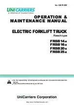
Summary of Contents for ESC 316

Page 1: ...06 13 11 14 51314819 ESC 316 316z Operating instructions G ESC 316z ESC 316 ...

Page 2: ...G KHUHE GHFODUH WKDW WKH SRZHUHG LQGXVWULDO WUXFN GHVFULEHG EHORZ LQ GHWDLO FRPSOLHV ZLWK WKH XURSHDQ LUHFWLYHV 0DFKLQHU LUHFWLYH DQG 8 OHFWURPDJQHWLF RPSDWLELOLW 0 LQFOXGLQJ DPHQGPHQWV DV ZHOO DV WKH OHJLVODWLYH GHFUHH WR LQFRUSRUDWH WKH GLUHFWLYHV LQ QDWLRQDO ODZ 7KH VLJQDWRULHV DUH LQ HDFK FDVH LQGLYLGXDOO DXWKRULVHG WR FRPSLOH WKH WHFKQLFDO GRFXPHQWV 0RGHO 2SWLRQ 6HULDO QR HDU RI PDQXIDFWXUH ...

Page 3: ...11 14 EN 2 ...

Page 4: ...guarantee of particular features of the truck should therefore be assumed from the present operating instructions Safety notices and text mark ups Safety instructions and important explanations are indicated by the following graphics DANGER Indicates an extremely hazardous situation Failure to comply with this instruction will result in severe irreparable injury and even death WARNING Indicates an...

Page 5: ...11 14 EN 4 Copyright Copyright of these operating instructions remains with JUNGHEINRICH AG Jungheinrich Aktiengesellschaft Am Stadtrand 35 22047 Hamburg Germany Tel 49 0 40 6948 0 www jungheinrich com ...

Page 6: ... 16 4 Technical Specifications 18 4 1 Performance data 18 4 2 Dimensions 19 4 3 Weights 22 4 4 Tyre type 22 4 5 Mast versions 23 4 6 EN norms 24 4 7 Conditions of use 25 4 8 Electrical requirements 25 5 Identification points and data plates 26 5 1 Data plate 27 5 2 Truck capacity plate 28 C Transport and Commissioning 29 1 Lifting by crane 29 2 Transport 30 3 Using the Truck for the First Time 31 ...

Page 7: ...Lifting transporting and depositing loads 72 5 Troubleshooting 75 5 1 Truck does not start 76 5 2 Load cannot be lifted 76 6 Operating the truck without its own drive system 77 7 Load handler emergency lowering 79 8 Optional equipment 81 8 1 Display and control unit 81 8 2 Setting the time 82 8 3 Keypad CanCode o 83 8 4 ISM access module o 101 F Industrial Truck Maintenance 103 1 Operational Safet...

Page 8: ... 1 Correct Use and Application 135 2 Data plate 135 3 Safety Instructions Warning Indications and other Notes 136 4 Lead acid batteries with armour plated cells and liquid electrolyte 137 4 1 Description 137 4 2 Operation 138 4 3 Servicing lead acid batteries with armour plated cells 141 5 PzV and PzV BS lead acid batteries with sealed armour plated cells 142 5 1 Description 142 5 2 Operation 143 ...

Page 9: ...11 14 EN 8 ...

Page 10: ...d distance are indicated on the capacity plate and must not be exceeded The load must rest on the load handler or be lifted by an attachment approved by the manufacturer The load must be fully raised see Lifting transporting and depositing loads on page 72 The following operations are in accordance with regulations and are permitted Lifting and lowering loads Transporting lowered loads The followi...

Page 11: ...to a maximum of 12 Do not travel across or at an angle on inclines Travel with the load facing uphill Operation in partially public traffic WARNING Use under extreme conditions Using the truck under extreme conditions can result in malfunctions and accidents XSpecial equipment and authorisation are required if the truck is to be constantly used in extreme conditions especially in dusty or corrosiv...

Page 12: ...ties are excluded Furthermore accident prevention regulations safety regulations and operating servicing and repair guidelines must be followed The operating company must ensure that all users have read and understood these operating instructions NOTE Failure to comply with the operating instructions invalidates the warranty The same applies if improper work is carried out on the truck by the cust...

Page 13: ...11 14 EN 12 ...

Page 14: ...uneven ground The truck can lift open bottom or diagonal board pallets beyond the area of the load wheels as well as roll cages Loads can be stacked unstacked and transported over long distances up to 5 25 m depending on the mast type 1 1 Truck models and rated capacity The rated capacity depends on the model The rated capacity can be derived from the model name The rated capacity is not generally...

Page 15: ...11 14 EN 14 2 Travel direction definition The following determinations have been made for travel direction specification Item Travel direction 1 Left 2 Drive direction 3 Load direction 4 Right 1 2 3 4 ...

Page 16: ...oor plate height adjuster 7 o Control display unit 16 t Steering wheel 8 o CanCode code lock 17 t Battery 9 o ISM access module 18 t Load wheels 10 t Overhead guard 19 t Load handler 11 t Mast 20 t Deadman switch 12 t Multi Pilot 21 t Seat cover 13 t Emergency Disconnect switch t Standard equipment o Optional equipment 5 6 7 8 7 9 10 11 12 14 15 17 16 20 21 18 19 13 ...

Page 17: ...ignal fails to appear or a fault is identified the truck automatically brakes to a halt Control displays on the control and display unit o indicate the emergency stop Deadman switch The deadman switch ensures that the driver s feet do not extend outside the truck during travel The deadman switch in the foot compartment must be depressed to enable the driver to operate the truck Lifting and travel ...

Page 18: ...ed reduction as a function of the steer angle Curve Control o is optionally available Hydraulic system Infinitely variable lifting and lowering operations are performed by moving the Multi Pilot forward and back When lifting is activated the pump unit starts to operate supplying hydraulic oil from the oil reservoir to the lift cylinder If the truck is fitted with the z auxiliary lift the wheel arm...

Page 19: ...dditions reserved 4 1 Performance data ESC316 ESC316z Q Rated capacity 1600 kg Travel speed with without rated load 9 1 9 1 km h Lift speed with without rated load 0 13 0 24 0 14 0 23 m s Lower speed with without rated load 0 42 0 42 0 42 0 38 m s Max gradeability with without rated load 7 12 Drive motor Output S2 60 min 2 8 kW Lift motor Output S3 15 3 0 8 kW ...

Page 20: ...19 11 14 EN 4 2 Dimensions b11 b5 b2 x Wa e a 2 Ast a 2 h13 h2 h3 h1 h4 l2 y l1 l c m2 s 187 1278 h6 Q ...

Page 21: ...t 950 mm h13 Lowered height 90 mm l1 Length 2125 2155 mm l2 Headlength 975 1005 mm b2 Overall width drive 930 mm b5 Overall width of the load handler 570 mm s e l Load handler dimensions 60 185 1150 mm b10 Track width drive direction 645 mm b11 Track width load direction 385 mm m1 Ground clearance laden below mast 30 m2 Ground clearance centre wheelbase 30 25 mm Ast Working aisle width pallet 1000...

Page 22: ...21 11 14 EN b11 b5 b2 x Wa e a 2 Ast a 2 h13 h2 h3 h1 h4 l2 y l1 l c m2 s 187 1278 h6 Q ...

Page 23: ...attery 1459 1228 1432 1857 kg Axle loading unladen Drive direction load direction battery 1891 518 1190 495 kg Battery weight 380 kg ESC316 ESC316z Tyres Vulkollan Wheel size drive direction 230 x 77 mm Wheel size load direction 85 x 85 mm Caster wheel twin roller 140 x 54 mm Wheels no Drive direction x driven 2 1x Wheels no Load direction 4 ...

Page 24: ...995 100 2800 3372 2093 mm 2145 100 3100 3672 2243 mm 2345 100 3500 4072 2288 mm 2595 100 4000 4572 2288 mm 2695 100 4200 4772 2288 mm ZZ 1945 1373 2800 3372 2093 mm 2095 1523 3100 3672 2243 mm 2295 1723 3500 4072 2288 mm 2545 1973 4000 4572 2288 mm 2645 2073 4200 4772 2288 mm DZ 1945 1376 4200 4770 2093 mm 2295 1726 5250 5820 2288 mm ...

Page 25: ...n vibrations of the 2002 44 EC Vibrations operator directive The manufacturer offers a special service to measure these human vibrations see Human vibration measurement on page 123 Electromagnetic compatibility EMC The manufacturer confirms that the truck adheres to the limits for electromagnetic emissions and resistance as well as the static electricity discharge test in accordance with EN 12895 ...

Page 26: ...ed continually in conditions of extreme temperature or condensing air humidity fluctuations 4 8 Electrical requirements The manufacturer certifies compliance with the requirements for the design and manufacture of electrical equipment according to EN 1175 Industrial Truck Safety Electrical Requirements provided the truck is used according to its purpose ...

Page 27: ... the load handler 23 Warning Do not reach through the mast 24 Raise lower wheel arms 25 Capacity plate 26 Multi Pilot 27 Floor plate adjustment 28 Data plate 29 Test plaque 30 Attachment points for lifting by crane 31 Serial number 32 Model description X XXXX XX XX 22 23 24 25 26 27 28 30 31 29 32 ...

Page 28: ...erial number 34 33 34 36 35 37 44 40 43 42 41 39 38 Item Description Item Description 33 Type 39 Year of manufacture 34 Serial number 40 Load centre mm 35 Rated capacity kg 41 Output 36 Battery voltage V 42 Min max battery weight kg 37 Net weight w o battery kg 43 Manufacturer 38 Option 44 Manufacturer s logo ...

Page 29: ...g for a given load centre C in mm and corresponding lift height H in mm for the truck with a horizontal load Example of how to calculate the maximum capacity With a load centre distance C of 600 mm and a maximum lift height H of 3600 mm the max capacity Q is 1105 kg 600 X XXXX XX XX 1105 3600 45 ...

Page 30: ... when loading by crane XDo not stand under suspended loads XDo not enter or stand in a hazardous area XAlways use lifting gear with sufficient capacity for truck weight see truck rating plate XAlways attach the crane lifting gear to the prescribed strap points and prevent them from slipping XUse the lifting slings only in the prescribed loading direction XCrane slings should be fastened in such a ...

Page 31: ...ed XThe truck must be securely fastened when transported on a lorry or a trailer XThe lorry or trailer must have fastening rings XUse wedges to prevent the truck from moving XUse only fastening belts with sufficient strength XUse non slip materials to securing the load aids pallet wedges e g non slip mats Securing the industrial truck for transport Requirements Load the truck Park the truck secure...

Page 32: ...ia a tow lead with an external battery NOTE Cold store trucks XTrucks designed for use in cold stores have a cold store hydraulic oil and a protective frame instead of a mast guard on the mast XIf a truck with cold store oil is used outside the cold store the lowering speeds may increase Procedure Check the equipment is complete If necessary install the battery see Battery removal and installation...

Page 33: ...e truck has been parked for a long period the wheel surfaces may tend to flatten This flattening has a negative effect on the safety and stability of the truck Once the truck has covered a certain distance the flattening will disappear ...

Page 34: ...equipment must be available CAUTION The use of unsuitable fire protection equipment can result in scalding Extinguishing fires with water can cause a reaction with the battery acid This can result in scalding from the acid XUse powder extinguishers XNever extinguish a burning battery with water Battery maintenance The battery cell covers must be kept dry and clean The terminals and cable shoes mus...

Page 35: ...ruck can be hazardous The design weight and dimensions of the battery have a considerable effect on the operational safety of the truck in particular its stability and capacity The use of unsuitable batteries that have not been approved by Jungheinrich for the truck can lead to a deterioration of the braking system during energy recovery operations and also cause considerable damage to the electri...

Page 36: ... The following table shows which combinations are included as standard The battery weights can be taken from the battery data plate Batteries with non insulated terminals must be covered with a non slip insulating mat Battery type Capacity Weight 24 volt battery 796 x 210 x 782 mm LXWXH 3 PzS 465 Ah 380 kg ...

Page 37: ...vel surface In special cases the truck may need to be secured with wedges XFully lower the load handler XSelect a place to park where no other people are at risk of injury from the lowered load handler XIf the brakes are not working place wedges underneath the wheels of the truck to prevent it from moving Requirements Park the truck on a horizontal surface Park the truck securely see Parking the t...

Page 38: ...voltage and charge capacity XBefore charging check all cables and plug connections for visible signs of damage XVentilate the room in which the truck is being charged XThe battery cover must be open and the battery cell surfaces must be exposed during charging to ensure adequate ventilation XDo not smoke and avoid naked flames when handling batteries XWherever an industrial truck is parked for cha...

Page 39: ... charger operating instructions Switch on the charger charging begins automatically The battery is now charged Completing battery charging restoring the truck to operation NOTE If charging has been interrupted the full battery capacity will not be available Requirements The battery is fully charged Procedure Complete charging in accordance with the charger operating instructions Disconnect the bat...

Page 40: ...e slings have sufficient capacity to replace the battery XUse only approved battery replacement devices battery roller stand replacement trolley etc XMake sure the battery is securely located in the truck s battery compartment CAUTION Unsecured battery An unsecured battery can result in trapping and injury XWear safety shoes when removing and installing the battery XDo not reach between the batter...

Page 41: ...ry on page 36 Tools and Material Required Battery replacement trolley o Procedure Remove the battery connector 48 from the truck Place the battery connector on the battery Turn the battery lock 52 over and pull it up Flip the battery retainer 47 over Pull the battery 51 off the truck Z Observe the battery replacement trolley operating instructions The battery has now been removed 51 52 47 48 ...

Page 42: ...truck Z Place the battery cable on the tray so that it cannot be severed when the battery is inserted Push the battery 51 into the battery compartment Flip the battery retainer 47 back Insert the battery lock 52 in the truck chassis and flip it over Attach the battery connector 48 to the truck connector Z Observe the battery replacement trolley operating instructions The battery is now installed 5...

Page 43: ...at the wider side is over the battery Flip the battery lock 52 over and pull it up Keep pulling the battery 51 out of the truck until the battery is resting against the battery retainer Check the battery acid level All indicators should show sufficient acid level if necessary add battery water see Traction Battery Appendix on page 135 Push the battery 51 into the truck Flip the battery retainer 47...

Page 44: ...s duties and responsibilities and be instructed in the operation of the truck and shall be familiar with the operating instructions Safety shoes must be worn on pedestrian operated trucks Unauthorised use of truck The operator is responsible for the truck during the time it is in use The operator must prevent unauthorised persons from driving or operating the truck Do not carry passengers or lift ...

Page 45: ... or lowering falling operating equipment XInstruct unauthorised persons to leave the hazardous area XIn case of danger to third parties give a warning signal in good time XIf unauthorised persons are still within the hazardous area stop the truck immediately WARNING Falling objects can cause accidents Falling objects can injure the operator while the truck is being operated XThe operator must rema...

Page 46: ...45 11 14 EN 2 Displays and Controls 7 12 53 54 55 6 56 13 16 15 57 58 59 20 ...

Page 47: ...ator 12 Multi Pilot t Controls Travel in drive direction load direction Load handler lift lower 13 Emergency Disconnect switch t Disconnects the battery supply All electric functions are cut out and the industrial truck decelerates 15 Floor plate height adjuster t Button for releasing and adjusting the floor plate height 16 Steering wheel t Steers the truck 20 Deadman switch t Deadman switch press...

Page 48: ...47 11 14 EN 59 Backrest adjustment lever t Adjusts the backrest tilt Item Control Display Function 7 12 53 54 55 6 56 13 16 15 57 58 59 20 ...

Page 49: ...LED is red the load can no longer be lifted Lifting is only enabled when the battery connected is at least 70 charged If the LED flashes red and the truck is not ready for operation inform the manufacturer s service department Red flashing is a truck controller code The flashing sequence indicates the type of fault LED colour Charge status Green 40 100 Orange 30 40 Green orange flashes at 1 Hz 20 ...

Page 50: ...is adjustment is not made the battery may become damaged due to deep discharge NOTE Full discharge can damage the battery Self discharge can cause the battery to fully discharge Full discharge shortens the useful life of the battery XCharge the battery at least every 2 months Z Charge the battery see Charging the battery on page 37 If the residual capacity falls below the required level lifting is...

Page 51: ...ntified and rectified the fault Inspection before daily operation Procedure Check the whole of the outside of the truck for signs of damage and leaks Damaged hoses must be replaced immediately Check the battery attachment and wire connections for damage and make sure they are secure Check the battery connectors are secure Check the overhead guard for damage Check the load handler for visible signs...

Page 52: ...cedure Enter the operator position see Entry and exit on page 55 Pull the Emergency Disconnect switch 13 to unlock it Switch on the truck to do this Insert the key in the key switch 6 and turn it as far to the right as it will go Enter the code in the code lock 8 o Hold the card or transponder in front of the ISM access module and depending on the setting press the green button on the ISM access m...

Page 53: ...d rectified the fault Procedure Test warning indicators and safety devices Test the Emergency Disconnect function by pressing the Emergency Disconnect switch The main circuit is disconnected and no truck operations can be performed Now pull the Emergency Disconnect switch to unlock it Test the horn by pressing the warning signal button Test the effectiveness of the brakes see Brakes on page 66 Tes...

Page 54: ...d handler is dangerous and is strictly prohibited XPark the truck on a level surface In special cases the truck may need to be secured with wedges XFully lower the load handler XSelect a place to park where no other people are at risk of injury from the lowered load handler XIf the brakes are not working place wedges underneath the wheels of the truck to prevent it from moving ...

Page 55: ...lti Pilot 12 in the arrow direction Set the drive wheel to Straight ahead Switch off the truck to do this Turn the key in the key switch 6 anti clockwise as far as it will go Remove the key from the key switch 6 For CanCode 8 press the O key o Press the red key on the ISM access module o Press the Emergency Disconnect switch 13 The truck is parked 55 6 8 13 12 61 ...

Page 56: ...rements Load handler fully lowered Procedure Z Always enter and exit the truck facing the load direction To enter and exit hold onto the handle 62 Enter or leave the truck CAUTION No more than one person may operate the truck at a time 62 ...

Page 57: ...nd hold down on the floor plate height adjustment button 15 The floor plate can now be adjusted Set the floor plate 63 to the correct height by standing on it discharging it Release the floor plate height adjustment button 15 The floor plate is now adjusted and locked at the required height 63 15 ...

Page 58: ...while travelling Adjusting the driver s seat Procedure Sit down on the driver s seat Loosen the seat lock 57 and push it forward or backward to the desired position Lock the seat in position again Undo the backrest lock 59 and bring the backrest into its required position Lock the backrest in position again Set the seat cushioning to the required level by turning the adjusting wheel 58 The driver ...

Page 59: ...urface and point loading on the travel lanes At blind spots get a second person to assist The driver must ensure that the loading dock dock leveller cannot be removed or come loose during loading unloading Travel conduct The operator must adapt the travel speed to local conditions The truck must be driven at slow speed when negotiating bends or narrow passageways when passing through swing doors a...

Page 60: ... if it tips over XIf the truck tips over on the right side of the load direction hold onto the option bar with both hands XIf the truck tips over on the left side in the load direction hold onto the steering wheel or the display panel with both hands XNever hold onto the side where the truck is about to tip over XTilt your body in the opposite direction of fall Negotiating slopes and inclines Nego...

Page 61: ...rest and must leave the lift before the truck The driver must ensure that the loading ramp dock cannot move or come loose during loading unloading Type of loads to be carried The operator must make sure that the load is in a satisfactory condition Loads must always be positioned safely and carefully Use suitable precautions to prevent parts of the load from tipping or falling down Prevent liquid l...

Page 62: ...ly in emergencies CAUTION Faulty or non accessible Emergency Disconnect switches can cause accidents A faulty or non accessible Emergency Disconnect switch can cause accidents In dangerous situations the operator cannot bring the truck to a halt in time by applying the Emergency Disconnect switch XThe operation of the Emergency Disconnect switch must not be affected by any objects placed in its wa...

Page 63: ...gency Disconnect switch on in emergencies Releasing the Emergency Disconnect switch Procedure Pull the Emergency Disconnect switch 13 to unlock it All electrical functions are enabled and the truck is operational again provided the truck was operational before the Emergency Disconnect was pressed Z Trucks with CanCode and ISM access module remain switched off 6 8 13 20 12 3 2 7 ...

Page 64: ...20 Set the Multi Pilot 12 to the required travel direction Move the Multi Pilot 12 in the load direction 3 Travel in the load direction Move the Multi Pilot 12 in the drive direction 2 Travel in the drive direction Control the travel speed by moving the Multi Pilot 12 The further the Multi Pilot 12 is moved the greater the travel speed Z When the Multi Pilot 12 is released it automatically returns...

Page 65: ...ection unless the Multi Pilot is released in time XAfter setting off in the opposite direction apply the Multi Pilot gently or not at all XDo not perform any sudden steering operations XAlways face the direction of travel XMaintain an adequate overview of the route you are travelling Changing direction during travel Procedure Set the Multi Pilot 12 to the opposite direction while travelling The tr...

Page 66: ...ts Start up the truck see Preparing the truck for operation on page 51 Procedure Turn the steering wheel 16 to the left or right Z The wheel position is indicated on the display 7 o The truck is steered in the required direction 12 16 7 ...

Page 67: ...he service brake deadman switch By regenerative braking coasting brake CAUTION XUse the service brake in emergencies Braking with the service brake Procedure During travel take your foot off the deadman switch 20 The truck decelerates regeneratively at the maximum rate until it comes to a halt The parking brake then applies Regenerative braking Procedure While travelling release the Multi Pilot 12...

Page 68: ...must be pressed to lift lower or travel If the deadman switch is released during travel the truck decelerates at the maximum rate until it stops If the deadman switch is released during lifting or lowering the respective function cuts out immediately 20 12 ...

Page 69: ...rea XInstruct other people to move out of the hazardous area of the truck Stop working with the truck if people do not leave the hazardous area XIf people do not leave the hazardous area despite the warning prevent the truck from being used by unauthorised people XOnly carry loads that have been secured and positioned in accordance with regulations Use suitable precautions to prevent parts of the ...

Page 70: ...e Multi Pilot Short movement slow lift lower Large movement fast lift lower The load handler is raised 4 6 2 Lowering the load handler Requirements Prepare the truck for operation see Preparing the truck for operation on page 51 Deadman switch pressed see page 67 Procedure Push the Multi Pilot 12 in the arrow direction until you reach the required lift height Z The lift and lower speeds can be inf...

Page 71: ...porting goods on uneven surfaces Requirements Prepare the truck for operation see Preparing the truck for operation on page 51 Deadman switch pressed see page 67 Procedure Press the wheel arm lift button 54 on the Multi Pilot Z Press down on the button until the wheel arms have reached their maximum height The wheel arms are raised 12 54 55 ...

Page 72: ...the wheel arm lower button 55 on the Multi Pilot Z Press down on the button until the wheel arms are fully lowered The wheel arms are lowered Safety height on the ESC 316z Z To ensure the operational stability of the truck the wheel arms must first be lowered beyond a load handler lift height of approx 1 80 m before you can continue lifting Beyond this height wheel arm lift is inhibited ...

Page 73: ...ruck Stop working with the truck if people do not leave the hazardous area XOnly carry loads that have been correctly secured and positioned Use suitable precautions to prevent parts of the load from tipping over or falling off the truck XDamaged loads must not be transported XNever exceed the maximum loads specified on the load diagram XNever stand underneath a raised load handler XDo not stand o...

Page 74: ...til the pallet is against the back of the load handler see graphic to the right Z The load must not extend by more than 50 mm beyond the load handler tips Raise the load handler until the desired height is reached see page 69 The load is being raised NOTE Risk of material damage to the hydraulic unit When the mechanical stops of the load handler have been reached release the raise load handler but...

Page 75: ... at blind spots Do not travel across or at an angle on inclines Do not turn on slopes and inclines and always drive with the load facing uphill see graphic 4 7 3 Depositing a load CAUTION Loads must not be set down on transport or escape routes in front of safety installations or factory equipment that must be accessible at all times Requirements Storage location suitable for storing the load Proc...

Page 76: ... if a fault in the electronics system is displayed with a corresponding error code contact the manufacturer s service department Troubleshooting must only be performed by the manufacturer s customer service department The manufacturer has a service department specially trained for these tasks In order for customer services to react quickly and specifically to the fault the following information is...

Page 77: ...NCode PIN entered Enter correct PIN see page 85 Possible Cause Remedy Truck not operational Carry out all measures listed under Truck does not start Hydraulic oil level too low Check the hydraulic oil level see page 117 Battery discharge monitor has switched off Charge the battery see page 37 Faulty fuse Check fuses see page 119 Excessive load Note maximum capacity see data plate Switch in mast im...

Page 78: ...Required Two M5x45 screws Spanner wrench Procedure Switch off the truck to do this Turn the key in the key switch 6 anti clockwise as far as it will go Remove the key from the key switch 6 For CanCode 8 o press the O key Press the red button on the ISM access module o Press the Emergency Disconnect switch 13 Disconnect the battery Use wedges to prevent the truck from moving Remove the drive compar...

Page 79: ...accidents XThe covers battery cover side panels drive compartment cover etc must be closed during operation Fit the drive compartment cover see Drive compartment cover disassembly assembly on page 116 The brakes are now applied again The brake is now be applied without current WARNING Only return the truck to service when you have identified and rectified the fault ...

Page 80: ...o move out of the hazardous area of the truck during emergency lowering XDo not stand underneath a raised load handler XIf the load handler is lowered with the emergency lowering device below it the operator must be in a safe area to avoid any danger XDo not activate emergency lowering of the load handler when the load handler is in the rack XReport any defects immediately to your supervisor XMark...

Page 81: ...ameter pin tool etc Procedure Fully lower the floor plate 63 see Adjusting the floor plate height on page 56 Remove the screws 65 from the seat cover 66 Remove the seat cover 66 Using a suitable object push in and hold down on the emergency lowering valve 67 The load handler is lowered 65 66 63 67 ...

Page 82: ...75 Set travel speed for current profile max 5 bars 76 Slow travel activated reduced travel speed 77 Profile number travel profile 1 2 or 3 78 Deadman button not pressed 79 Information display 80 Service mode active icon illuminated service interval expired symbol flashes 81 Overtemperature 82 Slow travel button when illuminated the 76 icon illuminates 83 Parking brake button void 84 Shift key to s...

Page 83: ...for 8 secs until the Set Clock Time menu is displayed Set the time with the Up 82 and Down 86 keys Confirm with the Shift key 84 Set the minutes with the Up 82 and Down 86 keys Confirm with the Shift 84 or profile 85 keys to return to normal operating mode The time is now set 85 84 82 86 ...

Page 84: ...ters the settings in the code lock can be changed Newly supplied trucks have the code indicated on a sticker When using the truck for the first time change the master and user codes and remove the sticker User code factory setting 2 5 8 0 Master code factory setting 7 2 9 5 Z When allocating the codes ensure the rider trucks are given a different code than pedestrian trucks Parameter Description 0...

Page 85: ... key Pressing the o key switches the truck off and sets it to non operational status The o key indicates the follow operating conditions via a red green LED 91 Code lock function commissioning the truck Error display configuring the user code Adjusting the travel program depending on the setting and truck Setting and changing parameters SET key When you change the parameters the SET key 90 acts as...

Page 86: ...ed on Z If the LED 91 flashes red this means the wrong code has been entered Enter the code again The Set key 90 has no function in operating mode 8 3 3 Switching off the truck with the keypad CanCode Switching off the truck Procedure Press the O key 92 The truck is switched off and the LED 91 is lit red Z The truck can cut out automatically after a specified time If no travel steering or hydrauli...

Page 87: ...0 0 with the digit keys Confirm with the SET key 90 The LEDs 87 91 flash green Enter the valid master code again with the digit keys Confirm with the SET key 90 The LEDs 88 91 flash green Enter the valid master code with the digit keys Z The new master code must be different from existing user codes Confirm with the SET key 90 The LEDs 89 91 flash green Enter the new master code again with the dig...

Page 88: ...d see Change operator code on page 90 Delete the user code so that the required master code can be used see Delete individual user codes on page 92 The master codes to be changed do not match Switch off the truck see Switching off the truck with the keypad CanCode on page 85 Enter the master code again see Changing the master code on page 86 The master code entered is not the same length as the us...

Page 89: ...user code must also be different from the existing master code Confirm with the SET key 90 The LEDs 89 91 flash green Enter the new user code again with the digit keys Confirm with the SET key 90 Wait until the LED 91 flashes green The setting is saved Press the O key 92 The truck is switched off and the LED 91 is lit red Check the new user code Switch on the truck with the new user code see Prepa...

Page 90: ... by a master code Switch off the truck see Switching off the truck with the keypad CanCode on page 85 Choose a different user code see Add operator code on page 88 The newly entered user codes do not match Switch off the truck see Switching off the truck with the keypad CanCode on page 85 Add the user code again see Add operator code on page 88 Code log full Switch off the truck see Switching off ...

Page 91: ...e as that of the previously entered master code The new user code must also be different from the existing master code Confirm with the SET key 90 The LEDs 89 91 flash green Enter the new user code again with the digit keys Confirm with the SET key 90 Wait until the LED 91 flashes green The setting is saved Press the O key 92 The truck is switched off and the LED 91 is lit red Check the new user c...

Page 92: ...de to be changed does not exist Switch off the truck see Switching off the truck with the keypad CanCode on page 85 Check the user code entered The user codes to be changed do not match Switch off the truck see Switching off the truck with the keypad CanCode on page 85 Change the user code again see Change operator code on page 90 Tried to change the operator code to another user code that already...

Page 93: ...t keys Confirm with the SET key 90 The LEDs 89 91 flash green Enter the user code to be deleted again with the digit keys Confirm with the SET key 90 Wait until the LED 91 flashes green The user code is now deleted Press the O key 92 The truck is switched off and the LED 91 is lit red Check that the user code has been deleted Switch the truck on with the user code to be deleted see Preparing the t...

Page 94: ...on page 85 Repeat the entry making sure that the master code is the same length as the user code Tried to delete an operator code that does not exist Switch off the truck see Switching off the truck with the keypad CanCode on page 85 Check the user code entered The user codes to be changed do not match Switch off the truck see Switching off the truck with the keypad CanCode on page 85 Delete the u...

Page 95: ... 91 flash green Enter the code 3 2 6 5 with the digit keys Confirm with the SET key 90 Wait until the LED 91 flashes green All user codes are deleted Press the O key 92 The truck is switched off and the LED 91 is lit red Check that the user codes have been deleted Switch on the truck with a previous user code see Preparing the truck for operation with the keypad CanCode on page 85 After entering t...

Page 96: ...e user code 4 6 digit is always determined by the length of the master code Requirements To prepare the truck for operation see Preparing the truck for operation with the keypad CanCode on page 85 Procedure Delete all user codes see Delete all user codes on page 94 Enter the new master code 4 6 digit see Changing the master code on page 86 Add user codes again see Add operator code on page 88 The ...

Page 97: ...e is 1 minute maximum cutout time is 30 minutes 31 After 10 seconds the truck cuts out automatically Confirm with the SET key 90 Wait until the LED 91 flashes green The setting is saved Press the O key 92 The truck is switched off and the LED 91 lights up red Checking the truck s automatic cutout Switch on the truck with a valid operator code see Preparing the truck for operation with the keypad C...

Page 98: ...period of the truck For the following events the LED 91 flashes red Cause Remedy Cutout time entered is out of range Switch off the truck see Switching off the truck with the keypad CanCode on page 85 Enter the time again while making sure it is within range ...

Page 99: ...is displayed by the 87 88 89 LEDs LED 87 lit travel program 1 activated LED 88 lit travel program 2 activated LED 89 lit travel program 3 activated The configuration code is four digit and is comprised as follows 1st digit Specifies the authorisation for travel program 1 2nd digit Specifies the authorisation for travel program 2 3rd digit Specifies the authorisation for travel program 3 4 digit Sp...

Page 100: ...program 2 is blocked for the user code selected 1 Travel program 2 is enabled for the user code selected 3rd digit 0 Travel program 3 is blocked for the user code selected 1 Travel program 3 is enabled for the user code selected 4th digit 0 When the truck has been switched on with the selected user code no travel program is activated 1 When the truck has been switched on with the selected user cod...

Page 101: ...t for the travel programs again using the digit keys Confirm with the SET key 90 Wait until the LED 91 flashes green The travel programs are now assigned to the user code Press the O key 92 The truck is switched off and the LED 91 is lit red Checking the travel program configuration to the user code Switch on the truck with the configured user code see Preparing the truck for operation with the ke...

Page 102: ...o Z If the truck is equipped with an ISM access module or Can Code refer to the ISM Access Module operator manual Cause Remedy Blocked travel program defined as start travel program Switch off the truck see Switching off the truck with the keypad CanCode on page 85 Try again making sure the configuration code is entered correctly ...

Page 103: ...11 14 EN 102 ...

Page 104: ...y a specialist engineer in industrial trucks taking safety into account Keep permanent graphic records of the plans tests and completion of the changes Carry out and have authorised the respective changes to the capacity data plates decals and stickers as well as the operator and service manuals Attach permanent and clearly visible marking to the truck indicating the types of changes made the date...

Page 105: ...oups Customer Services Customer Services are specially trained in the use of the truck and are able to carry out maintenance and repairs independently Customer Services are aware of the relevant standards guidelines and safety regulations as well as potential risks Operating company The maintenance personal of the operating company has the technical expertise and experience to perform the activiti...

Page 106: ...ON Consumables and used parts are an environmental hazard Used parts and consumables must be disposed of in accordance with the applicable environmental protection regulations To change the oil contact the manufacturer s customer service department who have been specially trained for this task XNote the safety regulations when handling these materials 2 3 Wheels WARNING The use of wheels that do n...

Page 107: ...l XCall for a doctor immediately in the event of an injury XDo not touch pressurised hydraulic hoses XReport any defects immediately to your supervisor XMark defective truck and take it out of service XDo not return the industrial truck to service until you have identified and rectified the fault NOTE Testing and replacing hydraulic hoses Hydraulic hoses can become brittle through age and must be ...

Page 108: ...pins must always be clean and well lubricated XLift chains should only be cleaned with paraffin derivatives e g petroleum or diesel fuels XDo not clean lift chains with high pressure jets or chemical cleaning agents XImmediately after cleaning dry the lift chain with compressed air and apply a chain spray XAlways lubricate a chain when it is discharged XLubricate a lift chain with particular care ...

Page 109: ...es in prescribed containers XAlways fill consumables in clean containers XDo not mix up different grades of consumable The only exception to this is when mixing is expressly stipulated in the operating instructions CAUTION Spilled consumables can cause slipping and endanger the environment Risk of slipping from spilled consumables The risk is greater when combined with water XDo not spill consumab...

Page 110: ...r parts XDo not smoke when handling oil XAvoid contact and digestion If you swallow oil do not induce vomiting but seek medical assistance immediately XSeek fresh air after breathing in oil fumes or vapours XIf oil has come into contact with your skin rinse your skin with water XIf oil has come into contact with your eyes rinse them with water and seek medical assistance immediately XReplace oil s...

Page 111: ...tion Schedule 1 Compound ratio for cold store usage 1 1 g Contact surfaces Cold store application s Grease nipple a Transmission oil drain plug c Hydraulic oil drain plug Hydraulic oil filler plug C 1 05 l A B A D D E 1 D a c ...

Page 112: ...ngheinrich hydraulic oil may be mixed with one of the named alternative hydraulic oils Grease guidelines Code Order no Package quantity Description Used for A 51 132 826 1 0 l Jungheinrich hydraulic oil Hydraulic system 51 132 827 5 0 l Jungheinrich hydraulic oil B 51 081 875 5 0 l H LP 10 DIN 51524 Hydraulic system C 50 380 904 5 0 l HSY 75W 90 Transmission D 29 201 430 1 0 kg Grease DIN 51825 Lu...

Page 113: ...ally provided for this purpose In order to raise and jack up the truck safely proceed as follows XJack up the truck only on a level surface and prevent it from moving accidentally XAlways use a jack with sufficient capacity When jacking up the truck take appropriate measures to prevent it from slipping or tipping over e g wedges wooden blocks XIn order to raise the truck the lifting gear must only...

Page 114: ...e g by short circuiting CAUTION Risk of component damage when cleaning the truck Cleaning with a pressure washer can result in malfunctions due to humidity XCover all electronic system assemblies controllers sensors motors etc before cleaning the truck with a pressure washer XDo not hold the jet of the pressure washer by the marked points to avoid damaging them see Identification points and data p...

Page 115: ...ck with water based solvents and water Use a sponge or cloth to clean In particular clean the following areas Window s Oil filler ports and their surroundings Grease nipples before lubrication Dry the truck after cleaning e g with compressed air or a dry cloth Carry out all the tasks in the section Recommissioning the truck after cleaning or maintenance work see Restoring the truck to service afte...

Page 116: ... Preparing the truck for maintenance and repairs on page 112 Tools and Material Required Compressor with water separator Non conductive antistatic brush Procedure Expose the electrical system see Drive compartment cover disassembly assembly on page 116 Clean the electrical system assemblies with weak suction or compressed air use a compressor with a water trap and not a conductive anti static brus...

Page 117: ...screws Remove the four screws 94 with the Allen key The drive compartment cover is now disassembled Fitting the drive compartment panel Tools and Material Required Allen key Procedure CAUTION Arm trapping hazard There is a risk of trapping when you close the drive compartment cover XMake sure there is nothing between the cover and the truck when you close the cover Insert the cover 93 into the tru...

Page 118: ...hydraulic oil if necessary Z For the first filling approximately 0 6 l more hydraulic oil should be added Turn the lid 95 anti clockwise from the hydraulic reservoir 97 Add hydraulic oil of the correct grade until it lies above the 1 mark level see Consumables on page 111 Turn the lid 95 clockwise on the hydraulic reservoir 97 Fit the drive compartment cover see page 116 To restore the industrial ...

Page 119: ...aintenance and repairs see Preparing the truck for maintenance and repairs on page 112 Tools and Material Required Torque wrench Procedure Position the drive wheel 100 so that the wheel nuts 99 can be pulled through the hole 98 Tighten all the wheel nuts 99 through the hole 98 in the impact buffer with the socket wrench To do this tighten the wheel nuts in the prescribed order First of all tighten...

Page 120: ... the arm rest Check the fuse ratings against the table and replace if necessary Close the armrest The fuses are now checked Description To protect Rating A F 15 Main fuse 300 F1 Main control fuse 10 6F1 Discharge Indicator Hourmeter 2 9F22 Electromechanical components 10 3F6 Steer motor 30 F17 Not used 10 F15 F1 6F1 9F22 3F1 F17 ...

Page 121: ...nance and repairs Procedure Thoroughly clean the truck see page 113 Lubricate the truck according to the lubrication diagram see page 110 Clean the battery grease the terminals and connect the battery Charge the battery see page 37 Start up the truck see page 50 ...

Page 122: ...t 5 1 Prior to decommissioning Procedure Thoroughly clean the truck see Cleaning on page 113 Prevent the truck from rolling away accidentally Check the hydraulic oil level and replenish if necessary see Consumables on page 111 Apply a thin layer of oil or grease to any non painted mechanical components Lubricate the truck according to the lubrication schedule see Lubrication Schedule on page 110 C...

Page 123: ...ge 111 Clean the battery grease the terminals and connect the battery Charge the battery see Charging the battery on page 37 Replace transmission oil Condensation water could have formed Replace hydraulic oil Condensation water could have formed Z The manufacturer s customer service department is specially trained to carry out these operations Start up the truck see Preparing the Truck for Operati...

Page 124: ...e improper use A test report shall be produced The test results must be kept for at least the next 2 inspections The proprietor is responsible for ensuring that faults are immediately rectified Z A test plaque is attached to the truck as proof that it has passed the safety inspection This plaque indicates the due date for the next inspection 7 Final de commissioning disposal Z Final de commissioni...

Page 125: ...dust temperature fluctuations or multiple shifts NOTE To prevent damage due to wear the manufacturer recommends an on site application analysis to agree on appropriate service intervals The following maintenance checklist lists the activities to be performed and the respective intervals to be observed Maintenance intervals are defined as Z W maintenance interval activities should be performed by t...

Page 126: ... level and add demineralised water if necessary t 4 Check battery connector for damage test it and make sure it is secure t Travel W A B C 1 Check wheels for wear and damage t Chassis and Superstructure W A B C 1 Check doors and or covers t 2 Check labels are legible and complete t 3 Check overhead guard and or cab are secure and check for damage t 4 Check mast protection pane mast grille for dama...

Page 127: ... t 8 Check electric wiring for damage insulation damage connections Make sure wire connections are secure t Power supply W A B C 1 Check battery cable connections are secure grease terminals if necessary t 2 Check battery and battery components t 3 Test battery lock battery attachment t 4 Check acid density and battery voltage t 5 Check acid level and add demineralised water if necessary t 6 Check...

Page 128: ...re secure t 4 Check settings and wear levels of slide pieces and stops and adjust the slide pieces if necessary t 5 Check load chain setting and tension if necessary t 6 Check load chain lubrication and lubricate if necessary t 7 Check lateral clearance of the mast connections and the fork carriage t 8 Visually inspect the mast rollers and check contact surface wear level t 9 Test hydraulic system...

Page 129: ...4 EN 128 Steering W A B C 1 Test electric steering and its components t 2 Check steering head bearings steering play and steering toothing or steering chain Lubricate steering gear teeth or steering chain t ...

Page 130: ...pply W A B C 1 Test battery refill system and check for leaks t Electrical system W A B C 1 Check data recorder is secure and check for damage t Power supply W A B C 1 Replace air filter wadding t 2 Check hose connections and test the pump t Hydraulic operations W A B C 1 Check attachment is properly secured to the truck and the supporting elements t Electrical system W A B C 1 Check impact sensor...

Page 131: ...d level and add demineralised water if necessary t 4 Check battery connector for damage test it and make sure it is secure t Travel W A B C 1 Check wheels for wear and damage t Chassis and Superstructure W A B C 1 Check doors and or covers t 2 Check labels are legible and complete t 3 Check overhead guard and or cab are secure and check for damage t 4 Check mast protection pane mast grille for dam...

Page 132: ... t 8 Check electric wiring for damage insulation damage connections Make sure wire connections are secure t Power supply W A B C 1 Check battery cable connections are secure grease terminals if necessary t 2 Check battery and battery components t 3 Test battery lock battery attachment t 4 Check acid density and battery voltage t 5 Check acid level and add demineralised water if necessary t 6 Check...

Page 133: ...n rods for damage and leaks and make sure they are secure t 5 Check settings and wear levels of slide pieces and stops and adjust the slide pieces if necessary t 6 Check load chain setting and tension if necessary t 7 Check load chain lubrication and lubricate if necessary t 8 Check lateral clearance of the mast connections and the fork carriage t 9 Visually inspect the mast rollers and check cont...

Page 134: ...tomer specific load t 2 Lubricate truck according to the lubrication schedule t 3 Demonstration after servicing t Steering W A B C 1 Test electric steering and its components t 2 Check steering head bearings steering play and steering toothing or steering chain Lubricate steering gear teeth or steering chain t ...

Page 135: ...pply W A B C 1 Test battery refill system and check for leaks t Electrical system W A B C 1 Check data recorder is secure and check for damage t Power supply W A B C 1 Replace air filter wadding t 2 Check hose connections and test the pump t Hydraulic operations W A B C 1 Check attachment is properly secured to the truck and the supporting elements t Electrical system W A B C 1 Check impact sensor...

Page 136: ... operation for batteries in accordance with Ex I and Ex II see relevant certification 2 Data plate 101 102 103 107 109 43 36 39 104 106 105 110 44 111 108 101 Battery name 102 Battery type 39 Production week year manf 103 Serial number 104 Supplier number 36 Rated voltage 105 Rated capacity 106 Battery weight in kg 107 Number of cells 108 Electrolyte volume in litres 109 Battery number 43 Manufact...

Page 137: ...ting Keep away from naked flames and strong heat sources Always wear protective clothing e g safety goggles and safety gloves when working on cells and batteries batteries Always wash your hands after completing the work Use insulated tools only Do not physically alter the battery strike crush compress notch dent or modify it in any way Hazardous electric voltage The metal parts of the battery cel...

Page 138: ...he adjustment factor is 0 0007 kg l per K e g electrolyte density 1 28 kg l at 45 C corresponds to a density of 1 29 kg l at 30 C The electrolyte must conform to DIN 43530 Part 2 purity regulations 4 1 1 Battery nominal data 1 Product Traction battery 2 Nominal voltage 2 0 V x no of cells 3 Rated capacity C5 See data plate 4 Discharge current C5 5h 5 Nominal electrolyte density1 1 Reached within t...

Page 139: ...gative to negative and check that contacts on the battery terminal conducting system are secure Check the terminal screw torques M10 23 1 Nm of the terminal conductors and connectors Charge up the battery Check the electrolyte level Z The electrolyte level must be above the cell baffle or the top of the separator Add electrolyte with distilled water up to the nominal level Checks completed 4 2 3 D...

Page 140: ...ilate the room in which the truck is being charged XBattery cell surfaces must remain exposed during charging in order to ensure sufficient ventilation see truck operating instructions chapter D Charging the Battery XDo not smoke and avoid naked flames when handling batteries XWherever an industrial truck is parked for charging there must be no inflammable material or consumables capable of creati...

Page 141: ...ff charger ensuring the terminals are connect positive to positive and negative to negative Switch on the charger Battery charged Z Charging is considered to be complete when the electrolyte density and battery voltage remain constant for more than 2 hours Compensation charging Compensation charging is used to ensure the useful life and maintain capacity after full discharge and repeated insuffici...

Page 142: ... a visual inspection for dirt and physical damage If the battery is charged regularly according to the IU characteristic carry out a compensation charge 4 3 3 Monthly Towards the end of the charging process measure and record the voltages of all the cells with the charger switched on After charging measure and record the electrolyte density and the electrolyte temperature in all the cells Compare ...

Page 143: ...ses or hazardous electrolyte burns if the cell vessels are destroyed Z PzV batteries are low gassing but not gassing free Electrolyte The electrolyte is sulphuric acid which is fixed in gel The density of the electrolyte cannot be measured 5 1 1 Battery nominal data 1 Product Traction battery 2 Nominal voltage 2 0 V x no of cells 3 Rated capacity C5 See data plate 4 Discharge current C5 5h 5 Rated...

Page 144: ...se explosions The battery gives off a mixture of oxygen and hydrogen electrolytic gas during charging Gassing is a chemical process This gas mixture is highly explosive and must not be ignited XAlways disconnect the charger and truck before connecting or disconnecting the charger and battery XThe charger must be adapted to the battery in terms of voltage charge capacity and battery technology XBef...

Page 145: ... cells XAlways charge the battery with DC current XAll DIN 41773 charging procedures are permitted in the format approved by the manufacturer XAlways connect the battery to a charger that is appropriate to the size and type of the battery XIf necessary have the charger checked by the manufacturer s customer service department for suitability XDo not exceed limit currents in the gassing area in acc...

Page 146: ...plied with 0 004 V C per K Battery charged Z Charging is considered to be complete when the electrolyte density and battery voltage remain constant for more than 2 hours Compensation charging Compensation charging is used to ensure the useful life and maintain capacity after full discharge and repeated insufficient charging Z Compensation charging should be carried out weekly Trickle charging Batt...

Page 147: ... the previous ones Z Carry out the measurements after full charging and subsequent resting for at least 5 hours Z If you find significant differences compared with the previous measurements or differences between the cells contact the manufacturer s customer service department 5 3 4 Annually Measure the truck insulation resistance in accordance with EN 1175 1 Measure the battery insulation resista...

Page 148: ...ter replenishment system 6 1 Water replenishment system design 112 Water container 113 Tap connection with ball cock 114 Flow indicator 115 Shut off cock 116 Locking coupling 117 Battery lock connector 112 113 114 115 116 117 3 m ...

Page 149: ...d securely The plug systems have an optical level indicator a diagnostic port to measure the temperature and electrolyte density and a degassing port 6 3 Adding water Water should be added to the batteries just before the battery is fully charged This ensures that the amount of water added is mixed with the electrolyte 6 4 Water pressure The water replenishment system must be operated with a water...

Page 150: ...er used to fill up electrolyte must correspond to purified or distilled water Purified water can be produced through distillation or ion exchangers and is then suitable for the production of electrolyte 6 7 Battery tubing The tubing of the individual plugs is in accordance with the existing electric circuit No changes should be made 6 8 Operating temperature Batteries with automatic water replenis...

Page 151: ...s of the plugs must come into contact with solvent based materials or soap 6 10 Service mobile vehicle Mobile water filling vehicle with pump and filling gun to fill individual cells The immersion pump in the container generates the necessary filling pressure The service mobile must be at exactly the same height as the battery base ...

Page 152: ...onds for an unknown reason the filters must be checked and replaced if necessary Battery connection A hose is attached to the pump module which together with the charge leads is routed from the charger to the charging connector The air is passed on to the battery via the electrolyte circulation coupling ducts in the connector When routing make sure the hose is not bent Pressure monitoring module T...

Page 153: ...ted to severe temperature fluctuations the electrolyte may flow back into the hose system XAttach a separate coupling system to the air inlet line such as locking coupling on the battery side and through coupling on the air supply side Schematic illustration Electrolyte circulation on the battery and air supply via the charger ...

Page 154: ... close to a drainage system for processing the electrolytic rinsing water All health and safety as well as water and waste disposal regulations are observed when disposing of used electrolyte or rinsing water Protective goggles and clothing are worn Cell plugs are not removed or opened Clean the plastic components of the battery in particular the cell containers only with water or water based clot...

Page 155: ...hat the temperature does not exceed 60 C at a distance of 30cm behind the outlet nozzle Observe the maximum operating pressure of 50 bar Observe a minimum distance of 30 cm from the top of the battery The battery should be sprayed over its entire surface to avoid localised overheating Z Do not clean one spot for more than 3 seconds with the jet to avoid exceeding the maximum battery surface temper...

Page 156: ... cells for PzV batteries If the battery is to be taken out of service for a long period 3 months it should as far as possible be charged to 50 of its charge level and stored in a dry room protected from frost 10 Troubleshooting If any faults are found on the battery or charger contact the manufacturer s customer service department immediately Z The operations required must be carried out by the ma...

Page 157: ......

Reviews: