background image

Quick Start Guide

PTX10008 Packet Transport Router

IN THIS GUIDE

PTX10008 System Overview | 1

Step 1–Prepare the Site | 2

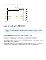
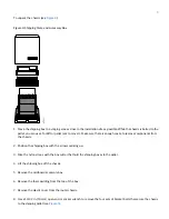
Step 2–Unpacking the PTX10008 | 4

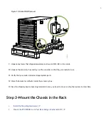
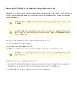
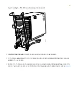
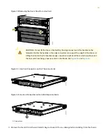
Step 3–Mount the Chassis in the Rack | 6

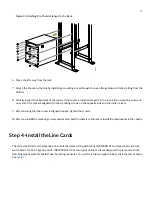
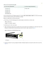
Step 4–Install the Line Cards | 11

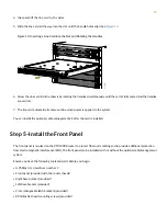
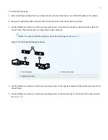
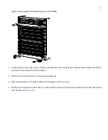
Step 5–Install the Front Panel | 14

Step 6–Connect Power to the Chassis | 19

Step 7–Connecting to the Network | 41

Step 8–Perform the Initial Configuration | 42

Safety Warnings Summary | 44

PTX10008 System Overview

NOTE:

The PTX10008 Quick Start is designed to get your new router up and running in short order. For a full

description of all the components, the specifications, and unabridged installation instructions, see the PTX10008

Packet Transport Router Hardware Guide.

The Juniper Networks PTX10008 Packet Transport Router enables cloud and data center operators to smoothly transition

from 10-Gigabit and 40-Gigabit Ethernet networks to 100-Gigabit and 400-Gigabit Ethernet high-performance networks.

This flexible, 13 rack unit (13-U) modular chassis has eight line card slots that can support a maximum of 1152 10-Gigabit

Summary of Contents for PTX10008

Page 1: ...m Overview NOTE The PTX10008 Quick Start is designed to get your new router up and running in short order For a full description of all the components the specifications and unabridged installation instructions see the PTX10008 Packet Transport Router Hardware Guide The Juniper Networks PTX10008 Packet Transport Router enables cloud and data center operators to smoothly transition from 10 Gigabit ...

Page 2: ...can stack a maximum of three PTX10008 chassis in a four post rack if The rack is 42 U or greater The rack meets the strength requirements to support the weight of the chassis and the cabling A single PTX10008 chassis without optics and cabling can range from 145 2 lb 65 86 kg to 421 25 lb 191 07 kg The facility has adequate cooling and power to support additional systems Power Requirements The PTX...

Page 3: ... 2 Clearance Requirements for Airflow and Hardware Maintenance for a PTX10008 with JNP10008 FAN2 g100666 30 in 76 2 cm Ports Clearance required for maintenance 19 in 48 3 cm Mounting flange width 24 in 61 cm FRUs Clearance required for maintenance 32 in 81 3 cm 33 7 85 6 cm 17 4 in 44 2 cm 34 2 in 86 8 cm If you are mounting a PTX10008 in a rack with other equipment ensure that the exhaust from ot...

Page 4: ...13 32 in 10 mm open end or socket wrench to remove the bracket bolts from the shipping pallet A box cutter or packing knife to slice open the nylon straps and tape that seal the crate and boxes The chassis ships in a cardboard box that has a two layer wooden pallet base with foam cushioning between the layers The router chassis is bolted to the pallet base The shipper has the option to either ship...

Page 5: ...omponents from the chassis 2 Position the shipping box with the arrows pointing up 3 Slice the nylon straps with the box cutter that hold the shipping boxes to the pallet 4 Lift the shipping box off the chassis 5 Remove the cardboard accessory box 6 Remove the foam padding from the top of the box 7 Remove the plastic cover from the router chassis 8 Use a 13 32 in 10 mm open end or socket wrench to...

Page 6: ...ey are ready for use 11 Verify that your order includes all appropriate parts 12 Store the brackets and bolts inside the accessory box 13 Save the shipping box and packing materials in case you need to move or ship the router at a later time Step 3 Mount the Chassis in the Rack 1 Install the Mounting Hardware 7 2 Mount the PTX10008 in a 4 Post Rack Using a Mechanical Lift 9 6 ...

Page 7: ...taching the bracket to the rack The rear brackets are interchangeable you can use either of the rear brackets with the right or left base bracket Ensure that you have the following parts and tools available to install the mounting hardware A Phillips screwdriver number 1 2 or 3 depending on the size of your rack screws A Phillips screwdriver number 2 to install the screws that connect the rear and...

Page 8: ... the installed left base bracket so that it is on the same rack level as the left base bracket If the right and left base brackets are not on the same level the chassis will rest at an angle in the rack instead of resting flat and level Line up the right base bracket s front screw holes with the holes in the rack Use four mounting screws appropriate for your rack to attach the right base bracket t...

Page 9: ...t and is adequately supported at the installation site Ensure that you have the following parts and tools available to install the router A mechanical lift rated for 500 lb 226 8 kg 14 mounting screws appropriate for your rack A Phillips screwdriver number 2 or number 3 depending on the size of your rack mounting screws CAUTION If you are installing more than one router in a rack or cabinet instal...

Page 10: ...assis approximately 0 75 in 1 9 cm above the surface of the base brackets Align the chassis as close as possible to the base brackets 5 Carefully slide the chassis onto the adjustable base and rear mounting brackets until the chassis flanges contact the rack rails The mounting brackets ensure that the holes in the flanges align with the holes in the rack rails See Figure 8 10 ...

Page 11: ...ide and the router is level 9 After ensuring that the router is aligned properly tighten the screws 10 After you install the mounting screws and securely bolt the chassis to the rack reinstall the components in the chassis Step 4 Install the Line Cards The line cards fall into two categories line cards that mate with switch fabric JNP10008 SF and those that mate with switch fabric for 14 4 Tbps li...

Page 12: ...s Ensure that you have the following parts and tools available to install a line card in the router ESD grounding strap Phillips screwdriver number 2 To install a line card in the router chassis 1 Attach the ESD grounding strap to your bare wrist and connect the strap to the ESD point on the router chassis The ESD point is located above the status LED panel on the front of the router chassis See F...

Page 13: ...card Lifting the line card by the handles or edge connectors might bend them which would prevent the line cards from being properly seated in the chassis See Figure 11 and Figure 12 Figure 11 Line Card Connectors on 14 4 Tbps Line Cards g051216 Figure 12 Line Card Connectors on Non 400 Gbps Line Cards 1 Connectors 3 Remove the line card from the electrostatic bag and inspect it for any damage befo...

Page 14: ...u can install the optional cable management kit after the card is installed Step 5 Install the Front Panel The front panel is required on the PTX10008 router to protect fiber optic cabling and to provide additional protection from electromagnetic interference EMI The front panel can be installed with or without the optional cable management system Ensure you have the following tools and parts befo...

Page 15: ...eft side of the chassis frame The base brackets are larger than the latch brackets NOTE The right and left base bracket cannot be interchanged see Figure 14 Figure 14 Front Panel Mounting Hardware g050602 2 1 3 3 1 Left base bracket Latch brackets 2 Right base bracket 4 Use the Phillips screwdriver to attach two mounting screws to the right base bracket at the bottom right side of the chassis fram...

Page 16: ...re are brackets on all four corners of the front of the chassis 7 Lift the front panel and rest it on the two bottom brackets 8 Slide the panel back on the bracket glides until it engages on the two ramps 9 Tilt the panel towards the chassis until it is vertical with the chassis The blue release buttons on the side of the panel click into place see Figure 16 16 ...

Page 17: ...he optional air filter in the front panel 1 Attach an ESD grounding strap to your bare wrist and connect the strap to one of the ESD points on the chassis 2 Turn the knob of the air filter frame anti clockwise and move it over the top of the front panel See Figure 17 17 ...

Page 18: ...Figure 17 Air Filter Frame in a PTX10008 Front Panel g100731 1 1 Air filter frame 3 Hold the air filter with both hands and insert it into the front panel until it stops See Figure 18 18 ...

Page 19: ...he air filter frame clockwise back in place NOTE You must replace the filter every 6 months Step 6 Connect Power to the Chassis IN THIS SECTION Ground the PTX10008 20 Install AC Power Supplies JNP10K PWR AC 21 Install AC HVAC HVDC Power Supplies JNP10K PWR AC2 25 Install DC Power Supplies JNP10K PWR DC 29 Install Dual DC Power Supplies JNP10K PWR DC2 35 19 ...

Page 20: ...tached lug can damage the switch Ensure that you have the following parts and tools available An electrostatic discharge ESD grounding strap provided Protective earthing terminal lug provided Grounding cable for your PTX10008 not provided The grounding cable must be 6 AWG 13 3 mm minimum 90 C wire or as permitted by the local code Grounding lug for your grounding cable provided This bracket attach...

Page 21: ...lace the two screws over the grounding lug and grounding cable 7 Tighten the two 10 32 screws using a Phillips screwdriver and apply torque between of 30 1 in lb 3 4 N m and 42 04 in lb 4 75 N m 8 Dress the grounding cable and ensure that it does not touch or block access to other device components and that it does not drape where people can trip over it Install AC Power Supplies JNP10K PWR AC The...

Page 22: ... the electrostatic discharge ESD grounding strap to your bare wrist and connect the strap to the ESD point on the chassis There is an ESD point located next to the protective earthing terminal and below PSU 5 on the PTX10008 rear panel see Figure 19 2 If the power supply slot has a cover panel on it insert your thumb and forefinger into the finger holes squeeze and pull the cover out of the slot S...

Page 23: ...pply slot on the rear of the system 9 Slide the power supply straight into the chassis until the power supply is fully seated in the slot Ensure the power supply faceplate is flush with any adjacent power supply faceplates or power supply cover panels see Figure 22 10 Push the captive screw into the power supply faceplate Ensure that the screw is seated inside the corresponding hole on the facepla...

Page 24: ...wo sides of the power cord retainer clip and insert the ends of the clip into the holes in the bracket on each side of the AC appliance inlets on the AC power supply faceplate See Figure 24 14 Locate two power cords shipped with the router the cords have plugs appropriate for your geographical location 15 Insert the power cord coupler into the power supply Each AC power supply has two independent ...

Page 25: ...t the INP1 and INP2 LEDs on the power supply faceplate are lit and are on steadily 20 Press the power switch to the on position Install AC HVAC HVDC Power Supplies JNP10K PWR AC2 The JNP10K PWR AC2 power supply is a high capacity high line model that is designed to support either AC or DC systems in either a low power or high power mode The power supply takes AC input and provides DC output of 12 ...

Page 26: ...ng strap to your bare wrist and connect the strap to the ESD point on the chassis There is an ESD point located next to the protective earthing terminal and below PSU5 on the PTX10008 rear panel see Figure 19 2 If the power supply slot has a cover on it insert your thumb and forefinger into the finger holes squeeze and pull the cover out of the slot Save the cover for later use See Figure 25 for r...

Page 27: ...ure 26 9 Push the captive screw into the power supply faceplate Ensure that the screw is seated inside the corresponding hole on the faceplate 10 Tighten the captive screw by turning it clockwise by using the Phillips screwdriver number 1 When the screw is completely tight the latch locks into the router chassis Figure 26 Installing a JNP10K PWR AC2 in a PTX10008 g100608 NOTE The power supply fans...

Page 28: ...n 14 Set the three dip switches to set the inputs and whether the power supply is running at 3000 W 5000 W or 5500 W See Table 2 Set both enable switches to the on position when using both source inputs When not using source redundancy set the unused source to the O off position The LED turns red and indicates an error if a source input is not in use and the enable switch is on Table 2 Setting the...

Page 29: ...rd that services the DC circuit switch the circuit breaker to the OFF position and tape the switch handle of the circuit breaker in the OFF position CAUTION Before you connect power to the router a licensed electrician must attach a cable lug to the grounding and power cables that you supply A cable with an incorrectly attached lug can damage the router for example by causing a short circuit CAUTI...

Page 30: ...the electrostatic discharge ESD grounding strap to your bare wrist and connect the strap to the ESD point on the chassis There is an ESD point located next to the protective earthing terminal and below PSU 5 on the PTX10008 rear panel see Figure 19 2 Taking care not to touch power supply components pins leads or solder connections remove the power supply from its bag CAUTION See the heat symbol Th...

Page 31: ...e dual 1 4 in spaced 5 8 in apart The terminal must accommodate double hole standard lug terminal for 4 AWG or larger wire 9 Verify that the DC power cables are correctly labeled before making connections to the power supply In a typical power distribution scheme where the return is connected to chassis ground at the battery plant you can use a multimeter to verify the resistance of the 48V and RT...

Page 32: ...cable lug to the RTN return DC power input terminal b Secure each negative DC source power cable lug to the 48V input DC power input terminal Figure 29 Connecting the DC Power Supply Cables to a JNP10K PWR DC Each power supply has two independent sets of DC power input terminals INPUT 1 RTN 48V 60V and INPUT 2 RTN 48V 60V For feed redundancy each power supply must be powered by dedicated power fee...

Page 33: ...power supply to release the latch NOTE You can install the power supplies in any slot labeled PSU 0 through PSU 5 top to bottom on a PTX10008 15 Using both hands place the power supply in the power supply slot on the rear of the router 16 Slide the power supply straight into the chassis until the power supply is fully seated in the slot Ensure the power supply faceplate is flush with any adjacent ...

Page 34: ... open NO Ejector closed 19 Route INP1 cables to a power source and INP2 to another power source The JNP10K PWR DC shares power so if power dips on one input the power supply is able to load balance internally WARNING Ensure that the power cords do not block access to router components or drape where people can trip on them 20 Set the enable switches for input 1 and input 2 see Figure 32 34 ...

Page 35: ...ovides two power supplies in a single housing that accepts either 60 A or 80 A using four redundant input power feeds PS_0 and PS_1 each have redundant input feeds A0 and or B0 for PS_0 and A1 and or B1 for PS_1 The input is configured using a set of dip switches on the power supply faceplate The output is dependant on the settings of these dip switches Before you install an JNP10K PWR DC2 power s...

Page 36: ...he cable lugs provided attached The provided terminal lugs for the JNP10K PWR DC2 are Panduit LCD4 14A L or equivalent and sized for 4 AWG 21 1 mm 2 power source cables We recommend that you install heat shrink tubing insulation around the crimped section of the power cables and lugs 13 32 in 10 mm nut driver or socket wrench Phillips screwdrivers numbers 1 and 2 Multimeter To install a JNP10K PWR...

Page 37: ...e correctly labeled before making connections to the power supply In a typical power distribution scheme where the return is connected to chassis ground at the battery plant you can use a multimeter to verify the resistance of the 48V and RTN DC cables to chassis ground The cable with very high resistance indicating an open circuit to chassis ground is negative and will be installed on the 48V inp...

Page 38: ...dancy each power supply must be powered by dedicated power feeds derived from feed INPUT 1 and feed INPUT 2 This configuration provides the commonly deployed INPUT 1 INPUT 2 feed redundancy for the router There is basic insulation between the inputs and the chassis ground Also there is basic insulation between RTN input feeds Figure 34 Connecting the DC Power Supply Cables to a JNP10K PWR DC2 g100...

Page 39: ... the power supply straight into the chassis until the power supply is fully seated in the slot The power supply will protrude from the chassis about 2 in 5 cm see Figure 36 NOTE The power supply fans will start immediately when inserted into the chassis 15 Push the captive screw into the power supply faceplate Ensure that the screw is seated inside the corresponding hole on the faceplate 16 Tighte...

Page 40: ... them 18 Set the three dip switches to set the inputs and whether the power supply is running at 3000 W 5000 W or 5500 W See Table 3 and Figure 37 Set both enable switches to the on position when using both source inputs When not using source redundancy set the unused source to the O off position The LED turns red and indicates an error if a source input is not in use and the enable switch is on T...

Page 41: ... power supply faceplate are lit and are on steadily 20 Press the power switch to the on position Step 7 Connecting to the Network You can configure and manage the PTX10008 by using a dedicated console Every control board has a console port with an RJ 45 connector Use the console port to connect the device to the management console or to a console server The console port accepts a cable with an RJ ...

Page 42: ...rol Protocol DHCP server and a File Transfer Protocol anonymous FTP Hypertext Transfer Protocol HTTP or Trivial File Transfer Protocol TFTP server on which the software image and configuration files are stored For more information about using ZTP for provisioning the device see Understanding Zero Touch Provisioning in the Installation and Upgrade Guide Before you begin connecting and configuring t...

Page 43: ...t next hop address For Junos OS Evolved system edit root set system management instance root set routing instances mgmt_junos routing optins static route prefix prefix length next hop default gateway ip address 8 Configure the IP address and prefix length for the router management interface For standard Junos OS systems edit root set interfaces em0 unit 0 family inet address ip address prefix leng...

Page 44: ...commit Safety Warnings Summary This is a summary of safety warnings For a complete list of warnings including translations see PTX10008 Hardware Guide at https www juniper net documentation WARNING Failure to observe these safety warnings can result in personal injury or death Permit only trained and qualified personnel to install or replace router components Perform only the procedures described ...

Page 45: ...laces and watches Metal objects heat up when connected to power and ground and can cause serious burns or become welded to the terminals CAUTION Do not place a copper transceiver in an access port directly above or below another copper transceiver Damage to the access ports will occur Power Cable Warning Japanese The attached power cable is only for this product Do not use this cable for another p...

Reviews: