background image


ENGLISH


GR-D338AH


LYT1598-001A


EN


PAL


Dear Customer,


Thank you for purchasing this digital 
video camera. Before use, please 
read the safety information and 
precautions contained in the pages 
– 4 and 6 to ensure safe use of this 
product.


Please visit our Homepage on the World Wide Web for 
Digital Video Camera:

For Accessories


:


http://www.jvc.co.jp/english/cyber/

http://www.jvc.co.jp/english/accessory/


INSTRUCTIONS


DIGITAL VIDEO CAMERA


GETTING STARTED


7


VIDEO RECORDING & 
PLAYBACK


17


ADVANCED FEATURES


22


REFERENCES


35


TERMS


To deactivate the demonstration, 
set “DEMO MODE” to “OFF”. 
(


 pg. 22, 25) 


42


GR-D338AH_EN.book  Page 1  Wednesday, January 25, 2006  5:45 PM

Summary of Contents for GR-D328

Page 1: ...of this product Please visit our Homepage on the World Wide Web for Digital Video Camera For Accessories http www jvc co jp english cyber http www jvc co jp english accessory INSTRUCTIONS DIGITAL VIDEO CAMERA GETTING STARTED 7 VIDEO RECORDING PLAYBACK 17 ADVANCED FEATURES 22 REFERENCES 35 TERMS To deactivate the demonstration set DEMO MODE to OFF pg 22 25 42 GR D338AH_EN book Page 1 Wednesday Janu...

Page 2: ...patented and other proprietary technology and will operate only with JVC Data Battery Use the JVC BN VF707U VF714 VF733U battery packs Using generic non JVC batteries can cause damage to the internal charging circuitry Make sure you only use cassettes with the Mini DV mark This camcorder is designed exclusively for the digital video cassette Only cassettes marked can be used with this unit Remembe...

Page 3: ...VF707U VF714U VF733U battery packs and to recharge them or to supply power to the camcorder from an AC outlet use the provided multi voltage AC Adapter An appropriate conversion adapter may be necessary to accommodate different designs of AC outlets in different countries NOTES The rating plate serial number plate and safety caution are on the bottom and or the back of the main unit The rating inf...

Page 4: ...the viewfinder and or the LCD monitor can result in dropping the unit or in a malfunction Take care not to get your finger caught in the cassette holder cover Do not let children operate the camcorder as they are particularly susceptible to this type of injury Do not use a tripod on unsteady or unlevel surfaces It could tip over causing serious damage to the camcorder CAUTION Connecting cables Aud...

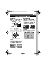
Page 5: ...setting of the camcorder by pressing the AUTO button pg 14 Backlight Compensation Simply pressing the BACKLIGHT button brightens the image darkened by backlight pg 28 You can also select a spot metering area so that more precise exposure compensation is available pg 29 Spot Exposure Control Data Battery You can check the battery status by simply pressing the DATA button pg 13 Major Features of thi...

Page 6: ...ty We recommend periodically cleaning the video heads with a cleaning cassette optional Be sure to store your cassette tapes and camcorder in the proper environment Video heads can become dirty more easily if your cassette tapes and camcorder are stored in a dusty area Cassette tapes should be removed from the camcorder and stored in cassette cases Store the camcorder in a bag or other container U...

Page 7: ...huttle Search 20 Blank Search 20 Playback Snapshot 20 Connections To A TV Or VCR 21 ADVANCED FEATURES 22 MENUS FOR DETAILED ADJUSTMENT 22 Changing The Menu Settings 22 Recording Menus 23 Playback Menus 25 FEATURES FOR RECORDING 26 Wide Mode 26 Night Scope 26 Snapshot Record still Image on Tape 26 Manual Focus 27 Exposure Control 27 Iris Lock 28 Backlight Compensation 28 Spot Exposure Control 29 Wh...

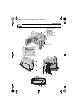
Page 8: ...8 EN MasterPage Left GETTING STARTED Index 3 3 3 7 7 7 6 6 6 5 5 5 4 4 4 9 9 9 8 8 8 2 2 2 1 1 1 21 22 25 27 28 29 30 31 23 24 26 32 GR D338AH_EN book Page 8 Wednesday January 25 2006 5 45 PM ...

Page 9: ...ATT pg 12 Recording Start Stop Button pg 17 Power Switch REC OFF PLAY pg 14 Lock Button pg 14 Cassette Open Eject Switch OPEN EJECT pg 16 Connectors The connectors are located beneath the covers Audio Video Output Connector AV pg 21 32 DC Input Connector DC pg 12 Digital Video Connector DV IN OUT i LINK pg 33 34 i LINK refers to the IEEE1394 1995 industry specification and extensions there of The ...

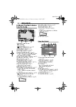
Page 10: ...by mode pg 17 PHOTO Appears when taking snapshot pg 26 Spot Exposure Control Indicator pg 29 Backlight Compensation Indicator pg 28 L Iris Lock Indicator pg 28 Exposure Adjustment Indicator pg 27 Wipe Fader Mode indicator pg 30 Wind Cut Indicator pg 24 Time Code pg 24 25 Manual Focus Adjustment Indicator pg 27 Brightness Control Indicator LCD monitor Viewfinder pg 15 Date Time pg 15 During Video P...

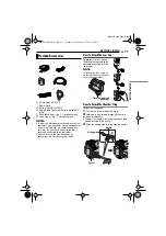
Page 11: ...ded cables for connections Do not use any other cables How To Attach The Lens Cap To protect the lens attach the provided lens cap to the camcorder as shown in the illustration NOTE To confirm the lens cap is on correctly make sure the cap is flush to the camcorder How To Attach The Shoulder Strap Follow the illustration 1 Thread the strap through the eyelet 2 Fold it back and thread it through th...

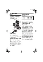
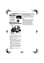
Page 12: ...the camcorder cannot be operated Charging is not possible if the wrong type of battery is used When charging the battery pack for the first time or after a long storage period the POWER CHARGE lamp may not light In this case remove the battery pack from the camcorder then try charging again If the battery operation time remains extremely short even after having been fully charged the battery is wo...

Page 13: ...nd hold for several seconds If COMMUNICATION ERROR appears instead of the battery status even though you tried to press DATA several times there may be a problem with your battery In such a case consult your nearest JVC dealer Using AC Power Perform step 4 in Charging The Battery Pack NOTE The provided AC Adapter features automatic voltage selection in the AC range from 110 V to 240 V About Batter...

Page 14: ...he LCD monitor and pull out the viewfinder fully The language on the display can be changed pg 22 24 1 Set the Power Switch to REC while pressing down the Lock Button located on the switch 2 Open the LCD monitor fully pg 17 Set the recording mode to M pg 15 3 Press MENU The Menu Screen appears 4 Press 3 or 4 to select DISPLAY and press SET or 2 The DISPLAY Menu ΰඊ appears 5 Press 3 or 4 to select ...

Page 15: ...wer Switch to REC while pressing down the Lock Button located on the switch 2 Make sure the LCD monitor is closed and locked Pull out the viewfinder fully and adjust it manually for best viewability 3 Turn the Diopter Adjustment Control until the indications in the viewfinder are clearly focused CAUTION When retracting the viewfinder take care not to pinch your fingers 1 Set the Power Switch to RE...

Page 16: ... may not be able to close the cassette holder cover Do not apply force Replace the battery pack with a fully charged one or use AC power before continuing 3 Close the cassette holder cover firmly until it locks into place To protect valuable recordings Slide the erase protection tab on the back of the tape in the direction of SAVE This prevents the tape from being recorded over To record on this t...

Page 17: ...m The Middle Of A Tape pg 19 To turn the melody sounds off pg 22 24 Tape Remaining Time Approximate tape remaining time appears on the display min means the camcorder is calculating the remaining time When the remaining time reaches 2 minutes the indication starts blinking The time required to calculate and display the remaining tape length and the accuracy of the calculation may vary according to...

Page 18: ...sired position and tilt the LCD monitor in the most convenient direction It can rotate 270 90 downward 180 upward Time Code During recording a time code is recorded on the tape This code is to confirm the location of the recorded scene on the tape during playback Frames are not displayed during recording If recording starts from a blank portion the time code begins counting from 00 00 00 minute se...

Page 19: ...rding Standby mode 2 Tape is rewound for about several seconds and played back automatically then pauses in the Recording Standby mode for the next shot Distortion may occur at start of playback This is normal Recording From The Middle Of A Tape 1 Play back a tape or use Blank Search pg 20 to find the spot at which you want to start recording then engage the Still Playback mode pg 20 2 Set the Pow...

Page 20: ...button normal playback resumes A slight mosaic effect appears on the display during Shuttle Search This is not a malfunction ATTENTION During Shuttle Search parts of the picture may not be clearly visible particularly on the left side of the screen Blank Search Helps you find where you should start recording in the middle of a tape to avoid time code interruption pg 19 1 Load a cassette pg 16 2 Se...

Page 21: ...mcorder pg 20 To choose whether or not the following displays appear on the connected TV Date Time Set DATE TIME to ON or OFF pg 22 25 Time Code Set TIME CODE to ON or OFF pg 22 25 Indications other than date time and time code Set ON SCREEN to OFF LCD or LCD TV pg 22 25 NOTES It is recommended to use the AC Adapter as the power supply instead of the battery pack pg 13 To monitor the picture and s...

Page 22: ...lection is complete Repeat the procedure if you wish to set other function menus The 3 indicator shows the setting that is currently saved inside the camcorder s memory 3 Press MENU The Menu Screen closes Video Playback Menus REC MODE pg 25 SOUND MODE pg 25 NARRATION pg 25 BRIGHT pg 25 DATE TIME pg 25 ON SCREEN pg 25 TIME CODE pg 25 1 The Sub Menu appears Example REC MODE Menu Press 3 or 4 to sele...

Page 23: ...cording mode is switched the playback picture will be blurred at the switching point It is recommended that tapes recorded in the LP mode on this camcorder be played back on this camcorder During playback of a tape recorded on another camcorder blocks of noise may appear or there may be momentary pauses in the sound 12BIT Enables video recording of stereo sound on four separate channels Equivalent...

Page 24: ...r Switch is set to PLAY Factory preset OFF Even though not heard while shooting shutter sound is recorded on the tape ON A melody sounds when any operation is performed It also activates the shutter sound effect pg 26 EXECUTE Resets all settings to the factory preset RETURN Does not reset all settings to the factory preset LCD The image is displayed on the LCD monitor when the viewfinder is pulled...

Page 25: ...ccess explanation on page 22 select SOUND MODE or NARRATION from the Menu Screen and set it to the desired parameter The settings below are effective only for video playback except REC MODE and BRIGHT The parameters except OFF in ON SCREEN SOUND MODE and NARRATION settings are the same as in the description on page 23 24 Allows you to set the video recording mode SP or LP depending on your prefere...

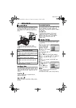
Page 26: ...tivity appears beside while the shutter speed is being automatically adjusted To deactivate Night Scope Press NIGHT again so that the Night Scope indicator disappears NOTES During Night Scope GAIN UP or DIS in SETTING menu pg 23 cannot be activated Night Scope cannot be activated simultaneously with SNOW or SPORTS of PROGRAM AE or all models of SHUTTER pg 31 During Night Scope it may be difficult ...

Page 27: ...ams or light reflecting off the surface of a body of water When shooting a scene with a high contrast background The following low contrast warnings appear blinking and Manual exposure control is recommended in the following situations When shooting using reverse lighting or when the background is too bright When shooting on a reflective natural background such as at the beach or when skiing When ...

Page 28: ...n appear 5 Press SET or 2 The iris is locked 6 Press MENU The Menu screen closes The L indication appears To return to automatic iris control Select AUTO in step 3 The exposure control indicator and L L L L disappear To lock the exposure control and the iris After step 3 adjust the exposure by pressing 3 or 4 Then lock the iris in steps 4 6 For automatic locking select AUTO in step 3 The exposure ...

Page 29: ...ure Control at the same time with following functions 16 9 in WIDE MODE pg 26 STROBE in EFFECT pg 31 Digital Zoom pg 18 Depending on the shooting location and condition optimum result may not be attained The white balance refers to the correctness of colour reproduction under various lighting If the white balance is correct all other colours will be accurately reproduced The white balance is usual...

Page 30: ...you adjust white balance manually the setting is retained even if the power is turned off or the battery removed These effects let you make pro style scene transitions Use them to spice up the transition from one scene to the next Wipe or Fader works when video recording is started or stopped 1 Set the Power Switch to REC 2 Set the recording mode to M pg 14 3 Set WIPE FADER to the desired mode pg ...

Page 31: ...ion playback The faster the shutter speed the darker the picture becomes Use the shutter function under good lighting conditions SNOW Compensates for subjects that may otherwise appear too dark when shooting in extremely bright surroundings such as in the snow SPOTLIGHT Compensates for subjects that may otherwise appear too bright when shooting under extremely strong direct lighting such as spotli...

Page 32: ...VCR s instruction manual 4 To stop dubbing stop recording on the VCR then stop playback on the camcorder NOTES It is recommended to use the AC Adapter as the power supply instead of the battery pack pg 12 To choose whether or not the following displays appear on the connected TV Date time Set DATE TIME to ON or OFF pg 22 25 Time code Set TIME CODE to OFF or ON pg 22 25 Indications other than date ...

Page 33: ...image may not appear in step 4 If this occurs turn off the power and make connections again When using a DV cable be sure to use the optional JVC VC VDV204U DV cable To use this camcorder as a recorder 1 Make sure all units are turned off 2 Connect this camcorder to a video unit equipped with a DV output connector using a DV cable as shown in the illustration 3 Set the camcorder s Power Switch to ...

Page 34: ...on the PC The date time information cannot be captured into the PC Refer to the instruction manuals of the PC and Software The still images can also be transferred to a PC with a DV connector equipped capture board The system may not work properly depending on the PC or capture board you are using Connection To A Personal Computer PC with DV connector To DV IN OUT To DV connector Core filter Core ...

Page 35: ... is open Close the cassette holder cover pg 16 Clean the video heads with an optional cleaning cassette pg 40 Advanced features Focus is set to the Manual mode Set Focus to the Auto mode pg 27 The lens is dirty or covered with condensation Clean the lens and check the focus again pg 38 The16 9 wide mode 16 9 indicator is selected Disengage the 16 9 indicator 16 9 wide mode pg 26 The camcorder is a...

Page 36: ...nplugged with power turned on Turn the camcorder s power off and on again then operate it In places subject to low temperature images become dark due to the characteristics of the LCD monitor This is not a malfunction Adjust the brightness and angle of the LCD monitor pg 15 17 When the LCD monitor s fluorescent light reaches the end of its service life images on the LCD monitor become dark Consult...

Page 37: ...ate time is not set pg 15 The built in clock battery has run out and the previously set date time has been erased Consult your nearest JVC dealer for replacement Appears for 5 seconds after power is turned on if the lens cap is attached or when it is dark Appears when pictures recorded in the HDV format are detected The pictures in the HDV format cannot be played back with this camcorder The error...

Page 38: ...the lens Blow it with a blower brush then wipe gently with lens cleaning paper To clean the viewfinder lens Remove dust from the viewfinder using a blower brush NOTES Avoid using strong cleaning agents such as benzine or alcohol Cleaning should be done only after the battery pack has been removed or other power units have been disconnected Mould may form if the lens is left dirty When using a clea...

Page 39: ...ry pack Cassettes To properly use and store your cassettes be sure to read the following cautions During use make sure the cassette bears the Mini DV mark be aware that recording onto prerecorded tapes automatically erases the previously recorded video and audio signals make sure the cassette is positioned properly when inserting do not load and unload the cassette repeatedly without allowing the ...

Page 40: ...ecording or playback the Head Clog Warning indicator appears Recording cannot be performed properly In such cases use an optional cleaning cassette Insert it and play back If the cassette is used more than once consecutively damage to the video heads may result After the camcorder plays back for about 20 seconds it stops automatically Also refer to the cleaning cassette s instructions If after usi...

Page 41: ...CD panel TFT active matrix system Viewfinder Electronic viewfinder with 0 33 black white LCD Speaker Monaural Format DV format SD mode Signal format PAL standard Recording Playback format Video Digital component recording Audio PCM digital recording 32 kHz 4 channel 12 BIT 48 kHz 2 channel 16 BIT Cassette Mini DV cassette Tape speed SP 18 8 mm s LP 12 5 mm s Maximum recording time using 80 min cas...

Page 42: ...s Lock 28 L LCD Monitor and Viewfinder 17 19 Loading A Cassette 16 M Manual Focus 27 Melody 24 Motor Drive Mode 26 N Night Scope 26 P Playback Sound 25 Power Linked Operation 12 Priority 24 Program AE 31 Q Quick Review 19 R Recording Capacity Tape 17 S Shutter Effects 31 Snapshot Mode 26 Sound Mode 23 25 Speaker Volume 20 Specifications 41 Spot Exposure Control 29 T Tape Speed REC MODE 23 25 Telep...

Page 43: ...MEMO GR D338AH_EN book Page 43 Wednesday January 25 2006 5 45 PM ...

Page 44: ...MasterPage BackCover EN GR D338AH Printed in Malaysia 0106MAR NF VM 2006 Victor Company of Japan Limited AH GR D338AH_EN book Page 43 Wednesday January 25 2006 5 45 PM ...

Reviews: