background image

LYT0710-001A

EN

INSTRUCTIONS

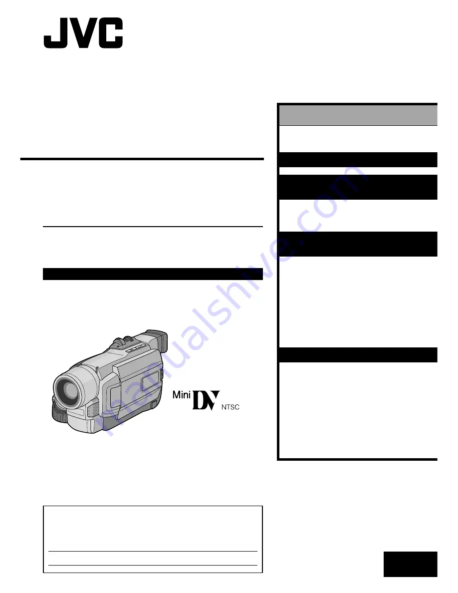
DIGITAL VIDEO CAMERA

GR-

DVL315

For Customer Use:

Enter below the Model No. and Serial No. which is located on the
bottom of cabinet. Retain this information for future reference.

Model No.

Serial No.

ENGLISH

CONTENTS

AUTOMATIC
DEMONSTRATION

5

GETTING STARTED

6 – 12

BASIC   RECORDING &
PLAYBACK

13 – 21

BASIC   RECORDING

............ 14 – 17

BASIC   PLAYBACK

.............. 18 – 21

ADVANCED

FEATURES

22 – 49

FOR RECORDING

................ 23 – 30

USING THE MENU FOR

DETAILED ADJUSTMENT

...... 31 – 36

DUBBING

......................... 37 – 38

USING THE REMOTE

CONTROL UNIT

................ 39 – 47

SYSTEM CONNECTIONS

........ 48 – 49

REFERENCES

50 – 67

DETAILS

................................... 51

TROUBLESHOOTING

............ 52 – 56

USER MAINTENANCE

................... 57

INDEX

............................. 58 – 62

CAUTIONS

........................ 63 – 65

TERMS

.................................... 66

SPECIFICATIONS

......................... 67

Please visit our Homepage on the World Wide
Web and answer our Consumer Survey
(in English only):

http://www.jvc-victor.co.jp/english/index-e.html

Summary of Contents for GR-DVL315

Page 1: ...CORDING PLAYBACK 13 21 BASIC RECORDING 14 17 BASIC PLAYBACK 18 21 ADVANCED FEATURES 22 49 FOR RECORDING 23 30 USING THE MENU FOR DETAILED ADJUSTMENT 31 36 DUBBING 37 38 USING THE REMOTE CONTROL UNIT 39 47 SYSTEM CONNECTIONS 48 49 REFERENCES 50 67 DETAILS 51 TROUBLESHOOTING 52 56 USER MAINTENANCE 57 INDEX 58 62 CAUTIONS 63 65 TERMS 66 SPECIFICATIONS 67 Please visit our Homepage on the World Wide We...

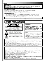
Page 2: ...o persons The exclamation point within an equilateral triangle is intended to alert the user to the presence of important operating and maintenance servicing instructions in the literature accompanying the appliance You are recommended to carefully read the cautions on pages 63 through 65 before use NOTES The rating plate serial number plate and safety caution are on the bottom and or the back of ...

Page 3: ...aged liquid has been spilled or objects have fallen into the apparatus the apparatus has been exposed to rain or moisture does not operate normally or has been dropped SAFETY PRECAUTIONS Do not point the lens or the viewfinder directly into the sun This can cause eye injuries as well as lead to the malfunctioning of internal circuitry There is also a risk of fire or electric shock CAUTION The foll...

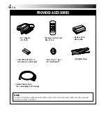
Page 4: ... plug to RCA plug Shoulder Strap Battery Pack BN V408U AC Adapter AP V10U Remote Control Unit RM V715U Lens Cap pg 5 for attachment PROVIDED ACCESSORIES NOTE In order to maintain optimum performance of the camcorder provided cables may be equipped with one or more core filter ...

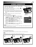
Page 5: ...l in The Menu Screen appears 2 Rotate the MENU BRIGHT wheel to select SYSTEM and press it The SYSTEM Menu appears 3 Rotate the MENU BRIGHT wheel to select DEMO MODE and press it The Sub Menu appears 4 Rotate the MENU BRIGHT wheel to select OFF and press it 5 Rotate the MENU BRIGHT wheel to select 1RETURN and press it twice The normal screen appears NOTE If you do not detach the Lens Cap you cannot...

Page 6: ...G STARTED GETTING STARTED CONTENTS Power 7 8 Grip Adjustment 9 Viewfinder Adjustment 9 Shoulder Strap Attachment 9 Tripod Mounting 9 Date Time Settings 10 Loading Unloading A Cassette 11 Recording Mode Setting 12 ...

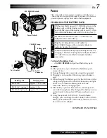
Page 7: ...pull out the battery pack NOTES If the protective cap is attached to the battery pack remove it first During charging the camcorder cannot be operated Charging is not possible if the wrong type of battery is used When charging the battery pack for the first time or after a long storage period the CHARGE lamp may not light In this case remove the battery pack from the camcorder then try charging ag...

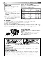
Page 8: ...it may cause a fire or explosion WARNING Do not allow the battery or its terminals to come in contact with metals as this can result in a short circuit and possibly start a fire The Benefits Of Lithium Ion Batteries Lithium ion battery packs are small but have a large power capacity However when one is exposed to cold temperatures below 10 C 50 F its usage time becomes shorter and it may cease to ...

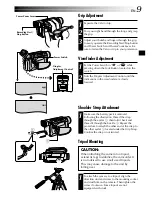
Page 9: ...ulder Strap Attachment 1 Make sure the battery pack is removed Following the illustration thread the strap through the eyelet 1 then fold it back and thread it through the buckle 2 Repeat the procedure to attach the other end of the strap to the other eyelet 3 located under the Grip Strap Confirm the strap is not twisted CAUTION When attaching the camera to a tripod extend its legs to stabilize th...

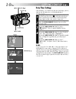
Page 10: ... select DISPLAY Press it and the DISPLAY Menu appears 4 Rotate the MENU BRIGHT wheel to select CLOCK ADJ Press it and month is highlighted Rotate the MENU BRIGHT wheel to input the month Press it Repeat to input the day year hour and minute Rotate the MENU BRIGHT wheel to select 1RETURN and press it twice The Menu Screen closes NOTE Even if you select CLOCK ADJ if the parameter is not highlighted ...

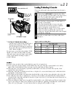
Page 11: ... still does not open turn the camcorder off then on again If the tape does not load properly open the cassette holder cover fully and remove the cassette A few minutes later insert it again When the camcorder is suddenly moved from a cold place to a warm environment wait a short time before opening the cassette holder cover Closing the cassette holder cover before the cassette holder comes out may...

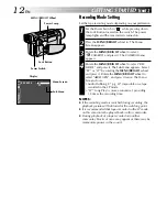
Page 12: ...RIGHT wheel and press it Rotate the MENU BRIGHT wheel to select 1RETURN and press it twice The Menu Screen closes Audio Dubbing pg 47 impossible on a tape recorded in the LP mode LP Long Play is more economical providing 1 5 times the recording time NOTES If the recording mode is switched during recording the playback picture will be blurred at the switching point It is recommended that tapes reco...

Page 13: ...RECORDING 14 17 Basic Recording 14 Journalistic Shooting 15 Self Recording 15 Operation Mode 15 Zooming 16 Video Light 16 Time Code 17 BASIC PLAYBACK 18 21 Normal Playback 18 Still Playback 18 Shuttle Search 18 Frame By Frame Playback 18 Blank Search 19 Connections 20 21 ...

Page 14: ... 3 Press the Recording Start Stop Button appears while recording is in progress To Stop Recording press the Recording Start Stop Button The camcorder re enters the Record Standby mode To Adjust The Brightness Of The Display rotate the MENU BRIGHT wheel until the bright level indicator on the display moves and the appropriate brightness is reached It is also possible to adjust the brightness of the...

Page 15: ...ur preference using the Power Switch Power Switch Position Manual Allows you to set various recording functions using the Menus If you want more creative capabilities than Full Auto recording try this mode Full Auto Allows you to record using NO special effects or manual adjustments Suitable for standard recording OFF Allows you to switch off the camcorder Allows you to play back a recording on th...

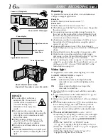
Page 16: ...l Zoom During Digital zoom the quality of image may suffer Digital zoom cannot be used when digital image processing such as Picture Wipe Dissolve pg 26 27 or Video Echo pg 25 is activated Macro shooting as close as approx 5 cm 2 to the subject is possible when the Power Zoom Lever is set all the way to W Also see TELE MACRO in the Menu Screen on page 33 Video Light To brighten the scene when natu...

Page 17: ...oting using a partially recorded tape When shooting on a blank portion located partway through the tape When shooting again after shooting a scene then opening closing the cassette holder cover Recording From The Middle Of A Tape 1 Play back a tape or use Blank Search pg 19 to find the spot at which you want to start recording then engage the Still Playback mode pg 18 2 Set the Power Switch to or ...

Page 18: ...ndications are displayed When a cable is connected to the AV connector the sound is not heard from the speaker Power Zoom Lever VOL Speaker Lock Button Still Playback Pauses during playback 1 Press 4 6 during playback 2 To resume normal playback press 4 6 again If still playback continues for more than about 3 minutes the camcorder s Stop mode is automatically engaged After 5 minutes in the Stop m...

Page 19: ...o cancel Blank Search midway press 5 NOTES In step 3 if the current position is at a blank portion the camcorder searches in the reverse direction and if the current position is at a recorded portion the camcorder searches in the forward direction Blank Search does not work if HEAD CLEANING REQUIRED USE CLEANING CASSETTE has appeared with the tape If the beginning or end of the tape is reached dur...

Page 20: ...Connection to a TV or VCR equipped with an S VIDEO IN and A V input connectors B Connection to a TV or VCR equipped only with A V input connectors When connecting the cables open this cover The Audio cable is not required for watching still images only BASIC PLAYBACK cont NOTE In order to maintain optimum performance of the camcorder provided cables may be equipped with one or more core filter If ...

Page 21: ... TV in the Menu Screen pg 35 NOTES It is recommended to use the AC Adapter as the power supply instead of the battery pack pg 8 The S Video cable is optional Be sure to use the YTU94146A S Video cable Consult the JVC Service Center described on the sheet included in the package for details on its availability Make sure to connect the end with a core filter to the camcorder The core filter reduces ...

Page 22: ... 30 USING THE MENU FOR DETAILED ADJUSTMENT 31 36 For Recording Menu 31 34 For Playback Menu 35 36 DUBBING 37 38 Dubbing To A VCR 37 Dubbing To Or From A Video Unit With A DV Connector 38 USING THE REMOTE CONTROL UNIT 39 47 Installing The Batteries Installing The Battery 39 Playback Zoom 41 Random Assemble Editing 42 45 For More Accurate Editing 46 Audio Dubbing 47 SYSTEM CONNECTIONS 48 49 Connecti...

Page 23: ...ive Mode Keeping SNAPSHOT pressed provides an effect similar to serial photography Interval between still images approx 1 second NOTES To remove the shutter sound BEEP on pg 31 33 Even if MULTI 4 or MULTI 9 is engaged Snapshot recording will be performed in the FULL mode during Digital Zoom or Night Alive pg 24 If Snapshot recording is not possible PHOTO blinks when SNAPSHOT is pressed If Program ...

Page 24: ...ring recording or during Record Standby Some modes of Program AE special effects cannot be used during Night Alive MENU BRIGHT Wheel Display Night Alive Makes dark subjects or areas even brighter than they would be under good natural lighting Although the recorded image is not grainy it may look as if it is strobing due to the slow shutter speed 1 Set the Power Switch to while pressing down the Lo...

Page 25: ... speed is fixed at 1 100th of a second The flickering that occurs when shooting under a fluorescent light or mercury vapor lamp is reduced This setting allows fast moving images to be captured one frame at a time for vivid stable slow motion playback The faster the shutter speed the darker the picture becomes Use the shutter function under good lighting conditions SNOW Compensates for subjects tha...

Page 26: ...ture Wipe or Dissolve works when video recording is started 1 Follow steps 1 through 4 above 2 If you select Picture Wipe Dissolve during recording press the Recording Start Stop Button when one scene is finished The point at which the scene ended is stored in memory If you select Picture Wipe Dissolve during Record Standby mode press the Recording Start Stop Button to start recording and press it...

Page 27: ...s out from top to bottom leaving a black screen Wipe in from the center of a black screen toward the top and bottom or wipe out from the top and bottom toward the center leaving a black screen The new scene gradually appears as the old one gradually disappears The new scene wipes in over the previous one from the upper right corner to the lower left corner The next scene gradually wipes in from th...

Page 28: ...turally When shooting a subject close to the lens zoom out first pg 16 If zoomed in in the auto focus mode the camcorder may automatically zoom out depending on the distance between the camcorder and the subject This will not occur when TELE MACRO pg 33 is activated FEATURE Manual Focus PURPOSE To obtain correct focus OPERATION 1 If you are using the viewfinder you should already have made the nec...

Page 29: ...rol mode is engaged Iris Lock Use this function in the following situations When shooting a moving subject When the distance to the subject changes so its size in the LCD monitor or the viewfinder changes such as when the subject is backing away When shooting on a reflective natural background such as at the beach or when skiing When shooting objects under a spotlight When zooming When the subject...

Page 30: ...a or Monotone pg 25 is activated Manual White Balance Operation Perform Manual White Balance when shooting under various types of lighting 1 Follow steps 1 through 4 of the white balance adjustment and select MWB 2 Hold a sheet of plain white paper in front of the subject Adjust zoom or position yourself so that the white paper fills the screen 3 Press the MENU BRIGHT wheel in until begins blinkin...

Page 31: ... the more detailed camcorder settings pg 32 34 1 Set the Power Switch to while pressing down the Lock Button located on the switch 2 Press the MENU BRIGHT wheel in The Menu Screen appears 3 Rotate the MENU BRIGHT wheel to select the desired function menu and press it The selected function menu appears 4 Function menu setting depends on the function If you have selected WIPE FADER PROGRAM AE or W B...

Page 32: ...ll appearance may be grainy but the image is bright The shutter speed is automatically adjusted 1 30 1 200 sec Shooting a subject in low or poor lighting at 1 30 sec shutter speed provides a brighter image than in the AGC mode but the subject s movements are not smooth or natural The overall appearance may be grainy While the shutter speed is being automatically adjusted is displayed To compensate...

Page 33: ...the screen and the image appears like a letterboxed 16 9 movie For playback on TVs with an aspect ratio of 16 9 Naturally expands the image to fit the screen without distortion appears When using this mode refer to your wide screen TV s instruction manual During playback recording on 4 3 TVs LCD monitor viewfinder the image is elongated vertically Disengages the function which cuts down on noise c...

Page 34: ...if the camcorder power is turned off If DEMO MODE remains ON some functions will not be available After viewing demo set to OFF Does not reset all settings to the factory preset Resets all settings to the factory preset Keeps the camcorder s display except the date time and time code from appearing on the connected TV screen Makes the camcorder s display appear on screen when the camcorder is conn...

Page 35: ...esired function and press it to display the Sub Menu 5 Rotate the MENU BRIGHT wheel to select the desired parameter and press it Selection is complete 6 Rotate the MENU BRIGHT wheel to select 1RETURN and press it twice to close the Menu Screen Display Power Switch MENU BRIGHT Wheel Lock Button Recording Start Stop Button NOTE REC MODE can be set when the Power Switch is set to or pg 12 32 Menu Scr...

Page 36: ... rewind During playback the sound mode is displayed in the upper left corner SOUND MODE 12BIT MODE Factory preset STEREO SOUND L SOUND R MIX SOUND 1 SOUND 2 Sound is output on both L and R channels in stereo Sound from the L channel is output in stereo Sound from the R channel is output in stereo Original and dubbed sounds are combined and output in stereo on both L and R channels in stereo Origin...

Page 37: ... As the camcorder starts to play your footage it will appear on your TV This will confirm the connections and the AUX channel for dubbing purposes Before you start dubbing make sure that the indications do not appear on the connected TV If they do they are being recorded onto the new tape To choose whether or not the following displays appear on the connected TV Date Time set DATE TIME to AUTO ON ...

Page 38: ...tion or disturbed image is played back on the player during dubbing the dubbing may stop so that an unusual image is not dubbed Even though the DV cable is connected correctly some times the image may not appear in step 4 If this occurs turn off the power and make connections again If Playback Zoom pg 41 or Snapshot is attempted during playback only the original playback image recorded on the tape...

Page 39: ...2 Insert the battery in the holder and be sure to have the mark visible 3 Slide the holder back in until you hear a click Read the caution concerning lithium batteries in the RM V700U instruction manual Installing The Batteries RM V715U provided The remote control uses two AAA R03 size batteries See General Battery Precautions pg 63 1 Open the battery compartment cover as illustrated 2 Insert two ...

Page 40: ...EDIT Buttons Functions With the camcorder s Power Switch set to the camera position or Transmits the beam signal Zoom in out pg 16 Functions the same as the Recording Start Stop Button on the camcorder With the camcorder s Power Switch set to Zoom in out pg 41 Playback start pg 18 Rewind Reverse Shuttle Search pg 18 Stops pg 18 Forward Forward Shuttle Search pg 18 Pause pg 45 pg 47 pg 43 pg 42 pg ...

Page 41: ... T W on the remote control Make sure the remote control is pointed at the camcorder s remote sensor Pressing T zooms in To end zoom press and hold W until magnification returns to normal Or press STOP 5 and then press PLAY 4 NOTES Zoom can also be used during still playback Due to digital image processing the quality of the image may suffer Remote sensor Press T Normal playback Zoom Buttons ...

Page 42: ...ards the VCR s infrared sensor Then referring to the VCR CODE LIST press and hold MBR SET and press button A and then B The code is automatically set once you release MBR SET and the VCR s power comes on 2 Make sure the VCR s power is on Then while holding VCR CTL press the button on the remote for the desired function The functions the remote can control are PLAY STOP PAUSE FF REW and VCR REC STB...

Page 43: ... Menu Screen pg 35 Playback Sound Mode Tape Speed And Tape Running Displays set ON SCREEN to LCD or LCD TV in the Menu Screen pg 35 In order to maintain optimum performance of the camcorder provided cables may be equipped with one or more core filter If a cable has only one core filter the end that is closest to the filter should be connected to the camcorder The S Video cable and the Editing cabl...

Page 44: ...egistered points press CANCEL on the remote control The registered points disappear one at a time from the most recently registered point NOTES When choosing a scene set Edit In and Edit Out points so that there is a relatively large difference between them If the search time for an in point exceeds 5 minutes the recording deck s Record Standby mode will be canceled and editing will not take place...

Page 45: ...ts Record Pause mode If you do not register an Edit Out point the tape will be dubbed all the way to the end automatically If you operate the camcorder during automatic editing the VCR will enter its Record Pause mode and automatic editing will stop 1 11 Engage the Stop modes for the camcorder and the VCR To make the R A Edit counter display disappear press ON OFF on the remote control NOTES Press...

Page 46: ...progress the VCR is slow to start recording Random Assemble Editing Menu Program 1 Remote sensor RM V700U optional VIDEO Menu ADJUSTMENT OF VCR CAMCORDER TIMING 4 Point the remote control at the camcorder s remote sensor and press ON OFF to make the Random Assemble Editing menu disappear then press the MENU BRIGHT wheel in The Menu Screen appears 5 Rotate the MENU BRIGHT wheel to select VIDEO and ...

Page 47: ...ng playback set 12BIT MODE to SOUND 2 or MIX in the Menu Screen pg 35 36 NOTES Sound is not heard from the speaker during Audio Dubbing When editing onto a tape that was recorded at 12 bit the old and new soundtracks are recorded separately If you dub onto a blank space on the tape the sound may be disrupted Make sure you only edit recorded areas If feedback or howling occurs during TV playback mo...

Page 48: ...e DV cable provided with the capture board The system may not work properly depending on the PC or capture board you are using To DV IN OUT DV cable optional To DV connector Power Switch PC with DV connector PC Core filter OR Core filter To RS 232C PC connection cable optional To PC DIGITAL PHOTO Connection To A Personal Computer A Using PC connection cable This camcorder can transfer still images...

Page 49: ...ded with GV DT3 to the printer s PC connector and the PC s RS 232C connector 4 Turn the camcorder s Power Switch to while pressing down the Lock Button located on the switch and turn on the other units NOTES It is recommended to use the AC Adapter as the power supply instead of the battery pack pg 8 If Still Playback Fast Forward or Rewind is attempted with the camcorder connected to a video unit ...

Page 50: ...50EN REFERENCES REFERENCES CONTENTS DETAILS 51 TROUBLESHOOTING 52 56 USER MAINTENANCE 57 INDEX 58 62 Controls Connectors And Indicators 58 59 Indications 60 62 CAUTIONS 63 65 TERMS 66 SPECIFICATIONS 67 ...

Page 51: ...the LCD monitor outdoors in direct sunlight the LCD monitor may be difficult to see If this happens use the viewfinder instead The cassette holder cannot be opened unless a power supply is attached There may be a delay after you open the cassette holder cover until the cassette holder opens Do not use force Once the cassette holder is closed it recedes automatically Wait until it recedes completel...

Page 52: ...nt light sources behind the subject The Sepia or Monotone mode is activated 1 Connect the AC Adapter securely 墌 pg 8 Replace the dead battery with a fully charged one 墌 pg 7 8 2 Set the date time 墌 pg 10 Consult your nearest JVC dealer for replacement 3 Set the tape s erase protection tab to REC 墌 pg 11 Set the Power Switch to or 墌 pg 15 Replace with new cassette 墌 pg 11 Close the cassette holder ...

Page 53: ...ene is ending At the end of the last selected scene for editing the Power Switch was set to OFF The power is off 9 Press the BACKLIGHT Button 墌 pg 29 10 Set PROGRAM AE to SPOTLIGHT in the Menu Screen 墌 pg 24 11 Set ZOOM to 40X or 400X in the Menu Screen 墌 pg 32 Disengage the VIDEO ECHO mode 墌 pg 16 25 Wait until the Picture Wipe or Dissolve effects are completed 墌 pg 16 26 12 Turn off Sepia and Mo...

Page 54: ...ring rapid panning 17 The Picture Wipe or Dissolve functions are in use WIDE MODE is set to SQUEEZE in the Menu Screen A Fade In or Fade Out is in progress 18 When shooting in the dark the unit becomes highly sensitive to light and the image takes on an effect similar to Slow Shutter 19 The Picture Wipe or Dissolve function is in use 20 The Sepia or Monotone mode is activated 21 This is a result o...

Page 55: ...ogy However black spots or bright spots of light red green or blue may appear constantly on the LCD monitor or the viewfinder These spots are not recorded on the tape This is not due to any defect of the unit Effective dots more than 99 99 30 This is normal 31 The Power Switch is set to or 25 Adjust the brightness and angle of the LCD monitor 墌 pg 14 15 26 Close the LCD monitor to turn it off or s...

Page 56: ... In this case the camcorder s functions become unusable 38 The temperature of the battery is extremely high low Charging is difficult in places subject to extremely high low temperatures 39 This is not a malfunction 40 The DV cable was plugged unplugged with power turned on 32 33 Turn the speaker volume down 墌 pg 18 34 Clean the video heads with an optional cleaning cassette 墌 pg 64 35 Wipe them g...

Page 57: ...an the interior of the viewfinder with it 2 6 Close the hatch Tilt the viewfinder back to the horizontal position NOTES Avoid using strong cleaning agents such as benzine or alcohol Cleaning should be done only after the battery pack has been removed or other power units have been disconnected Mold may form if the lens is left dirty When using a cleaner or chemically treated cloth refer to the cau...

Page 58: ...58EN INDEX Controls Connectors And Indicators P L A Y O FF 1 i o r u 3 4 5 6 7 Q W t Y R U T E q w 0 8 9 p 2 y e ...

Page 59: ... DIGITAL PHOTO Connector 墌 pg 48 J Terminal JLIP Joint Level Interface Protocol 墌 pg 43 Connect to a JLIP compatible camcorder or VCR to control it from the computer using the Software Connect the editing cable when performing Random Assemble Editing 墌 pg 42 46 Audio Video Output Connector AV 墌 pg 20 37 43 q DC Input Connector 墌 pg 7 8 w Digital Video Connector DV IN OUT i Link 墌 pg 38 48 49 i Lin...

Page 60: ...s engaged 墌 pg 32 8 Approximate zoom ratio Appears during zooming 墌 pg 16 9 Displays the selected Fade Wipe effect 墌 pg 26 27 0 Appears when in the Squeeze or Cinema mode 墌 pg 33 Appears during zooming Zoom level indicator 墌 pg 16 Displays the recording mode SP or LP 墌 pg 12 Displays the tape remaining time 墌 pg 14 REC appears during recording PAUSE appears during Record Standby mode 墌 pg 14 PHOTO...

Page 61: ...search 2 Rewind Shuttle search 6 Pause 64 Forward slow motion 16 Reverse slow motion e Audio Dubbing 6e Audio Dubbing Pause 1 L 2B 2 I 0 T 2 S B V 1 O L O U A L 2 N N U 5 D K M 1 E SEARC D H E 1 C 0 P 2 0 5 0 6 4 0 A 1 M S 1 2 3 4 7 6 5 5 Displays the date time 墌 pg 35 36 6 BRIGHT Displays the brightness of the LCD monitor 墌 pg 14 VOLUME Displays the speaker volume 墌 pg 18 The level indicator move...

Page 62: ...y runs out and the previously set date time is erased Consult your nearest JVC dealer for replacement Appears for 5 seconds after power is turned on if the lens cap is attached Appears if Audio Dubbing is attempted on a blank portion of a tape 墌 pg 47 Appears if Audio Dubbing is attempted on a tape recorded in the LP mode 墌 pg 47 Appears if Audio Dubbing is attempted on a tape recorded in 16 bit a...

Page 63: ...e using the supplied battery pack or an optional battery pack be sure to read the following cautions 1 To avoid hazards do not burn do not short circuit the terminals When transporting make sure the provided battery cap is attached to the battery If the battery cap is misplaced carry the battery in a plastic bag do not modify or disassemble do not expose the battery to temperatures exceeding 60 C ...

Page 64: ...trong magnetic or electric fields speakers broadcasting antennas etc in places subject to extremely high over 40 C or 104 F or extremely low under 0 C or 32 F temperatures CAUTIONS cont 3 DO NOT leave the unit in places of over 50 C 122 F in places where humidity is extremely low below 35 or extremely high above 80 in direct sunlight in a closed car in summer near a heater 4 To protect the unit DO...

Page 65: ... user is encouraged to try to correct the interference by one or more of the following measures Reorient or relocate the receiving antenna Increase the separation between the equip ment and receiver Connect the equipment into an outlet on a circuit different from that to which the receiver is connected Consult the dealer or an experienced radio TV technician for help Serious malfunctioning If malf...

Page 66: ... 墌 pg 11 M Manual Focus 墌 pg 28 Menu Screen CAMERA 墌 pg 32 Menu Screen DISPLAY 墌 pg 34 35 Menu Screen MANUAL 墌 pg 32 33 Menu Screen SYSTEM 墌 pg 33 34 35 Menu Screen VIDEO 墌 pg 35 Monotone 墌 pg 25 Motor Drive Mode 墌 pg 23 N Night Alive 墌 pg 24 P Picture Wipe Dissolve 墌 pg 26 27 Playback Zoom 墌 pg 41 Power Switch Position 墌 pg 15 Printer 墌 pg 49 Program AE With Special Effects 墌 pg 24 25 Provided Ac...

Page 67: ...l For Digital Video Camera Format DV format SD mode Signal format NTSC standard Recording Playback format Video Digital component recording Audio PCM digital recording 32 kHz 4 channel 12 bit 48 kHz 2 channel 16 bit Cassette Mini DV cassette Tape speed SP 18 8 mm s LP 12 5 mm s Maximum recording time SP 80 min using 80 min cassette LP 120 min For Connectors S Video Y 1 V p p 75 Ω analog C 0 29 V p...

Page 68: ...U Printed in Japan 1200HOV UN YP EN GR DVL315 VICTOR COMPANY OF JAPAN LIMITED COPYRIGHT 2001 VICTOR COMPANY OF JAPAN LTD ...

Reviews: