background image

VIDEO CASSETTE RECORDER

HR-A592U

INSTRUCTIONS

LPT0778-001A
COPYRIGHT © 2002 VICTOR COMPANY OF JAPAN, LTD.

Printed in Thailand

Dear Customer,

Thank you for purchasing the JVC VHS video cassette recorder.
Before use, please read the safety information and precautions to
ensure safe use of your new VCR.

CAUTIONS

WARNING

:

TO PREVENT FIRE OR SHOCK HAZARD, DO NOT EXPOSE
THIS UNIT TO RAIN OR MOISTURE.

CAUTION:

This video cassette recorder should be used with AC 120V~,
60Hz only.
To prevent electric shocks and fire hazards, DO NOT use any
other power source.

CAUTION:

TO PREVENT ELECTRIC SHOCK, MATCH WIDE BLADE OF PLUG
TO WIDE SLOT, FULLY INSERT.

ATTENTION:

POUR ÉVITER LES CHOCS ÉLECTRIQUES, INTRODUIRE LA
LAME LA PLUS LARGE DE LA FICHE DANS LA BORNE
CORRESPONDANTE DE LA PRISE ET POUSSER JUSQU’AU
FOND.

Note to CATV system installer:

This reminder is provided to call the CATV system installer’s
attention to Article 820-40 of the NEC that provides guidelines
for proper grounding and, in particular, specifies that the cable
ground shall be connected to the grounding system of the
building, as close to the point of cable entry as practical.

CAUTION:

Changes or modifications not approved by JVC could void user’s
authority to operate the equipment.
This equipment has been tested and found to comply with the limits
for a Class B digital device, pursuant to Part 15 of the FCC Rules.
These limits are designed to provide reasonable protection against
harmful interference in a residential installation. This equipment
generates, uses, and can radiate radio frequency energy and if not
installed and used in accordance with the instructions, may cause
harmful interference to radio communications. However, there is no
guarantee that interference will not occur in a particular installation. If
this equipment does cause harmful interference to radio or television
reception, which can be determined by turning the equipment off and
on, the user is encouraged to try to correct the interference by one or
more of the following measures:

Reorient or relocate the receiving antenna.
Increase the separation between the equipment and receiver.
Connect the equipment into an outlet on a circuit different from that
to which the receiver is connected.
Consult the dealer or an experienced radio/TV technician for help.

Failure to heed the following precautions may result in damage
to the VCR, Remote or video cassette.

1 DO NOT place the VCR . . .

...in an environment prone to extreme temperatures or humidity.
...in direct sunlight.
...in a dusty environment.
...in an environment where strong magnetic fields are generated.
...on a surface that is unstable or subject to vibration.

2. DO NOT block the VCR’s ventilation openings.
3. DO NOT place heavy objects on the VCR or on the Remote.
4. DO NOT place anything which might spill on the top of the VCR

or on the Remote.

5. AVOID violent shocks to the VCR during transport.

For Customer Use:

Enter below the Model No. and Serial No. which are located
on the rear of cabinet. Retain this information for future
reference.
Model No.
Serial No.

The lightning flash with arrowhead symbol, within
an equilateral triangle, is intended to alert the user
to the presence of uninsulated “dangerous voltage”
within the product’s enclosure that may be of
sufficient magnitude to constitute a risk of electric
shock to persons.

The exclamation point within an equilateral triangle
is intended to alert the user to the presence of
important operating and maintenance (servicing)
instructions in the literature accompanying the
appliance.

J4F90201A 

 K

02/12

• Cassettes marked “VHS” (or “S-VHS”) can be used with this video

cassette recorder. However, S-VHS recording is not possible with
this model.

• This model is equipped with SQPB (S-VHS QUASI PLAYBACK)

that makes it possible to play back S-VHS recordings with regular
VHS  resolution.

• HQ VHS is compatible with existing VHS equipment.
• As an Energy Star® Partner, JVC has determined that this product

or product model meets the Energy Star® guidelines for energy
efficiency.

*J4F90201A*

 4F90201A/Cov-07

11/15/02, 03:55 PM

1

Summary of Contents for HR-A592U

Page 1: ...quipment off and on the user is encouraged to try to correct the interference by one or more of the following measures Reorient or relocate the receiving antenna Increase the separation between the equipment and receiver Connect the equipment into an outlet on a circuit different from that to which the receiver is connected Consult the dealer or an experienced radio TV technician for help Failure ...

Page 2: ...e National Electrical Code ANSI NFPA 70 provides information with regard to proper grounding of the mast and supporting structure grounding of the lead in wire to an antenna discharge unit size of grounding connectors location of antenna discharge unit connection to grounding electrodes and requirements for the grounding electrode 2 Lightning For added protection for this product during a lightnin...

Page 3: ...Upon completion of any service or repairs to this product ask the service technician to perform safety checks to determine that the product is in safe operating condition How to use the Remote Before use insert two AAA size batteries into the Remote with the polarity and matched correctly as indicated on the battery compartment or on the lid Point the Remote toward the remote sensor on the target ...

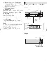
Page 4: ...N 00 00 00 SP 8 30 AM THU HI FI AUTO TR STEREO OPERATING MODE TAPE IN AUTO TRACKING HI FI STEREO AUTO REPEAT OUTPUT SELECTION Buttons Connectors and Indicators Antenna or cable Coaxial cable Flat feeder Matching transformer not supplied Back of VCR To audio video input connectors Audio video cable not supplied To 75 Ω terminal RF cable supplied TV RF Connection Disconnect the TV antenna from the T...

Page 5: ... difference of more than 5 minutes exists between the built in clock time and the actual time To Set Auto Clock To Off When shipped from factory AUTO CLOCK option is set to ON But if you do not want Auto Clock set Adjustment To view playback of a recorded tape or to watch a program selected by the VCR s channel selector the TV must be set to channel 3 or 4 video channel when a TV is connected with...

Page 6: ... SYSTEM SETUP ENTER MENU MENU TIMER REC SET AUTO REPEAT ON OFF ON OFF SAP CH SETUP SYSTEM SETUP TV CATV Selection Access Menu screen then CH Setup screen Press MENU on the Remote Press SET to select CH SETUP then press ENTER Access Menu screen Press MENU on the Remote Press SET to select SYSTEM SETUP then press ENTER ENTER MENU MENU TIMER REC SET AUTO REPEAT ON OFF ON OFF SAP CH SETUP SYSTEM SETUP...

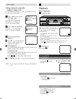
Page 7: ... 2 NOTE You can t select CH SET UP if you set the channel to L ENTER MENU MENU TIMER REC SET AUTO REPEAT ON OFF ON OFF SAP CH SETUP SYSTEM SETUP Make sure the window side is up the rear label side is facing you and the arrow on the front of the cassette is pointing towards the VCR Basic Playback Load a cassette Playback OR Press STOP EJECT on the VCR 1 2 Do not apply too much pressure when inserti...

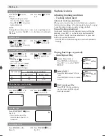
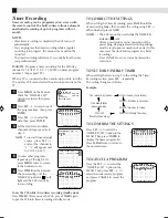
Page 8: ...CH SPEED PRESS ONCE PRESS TWICE SP EP 3X 9X 5X 15X Adjusting tracking condition Tracking Adjustment Automatic tracking adjustment Whenever you insert a tape and start playback automatic tracking starts working and continuously analyzes the signal to enable optimum picture quality during playback Manual tracking adjustment If automatic tracking cannot eliminate noises well during playback press SET...

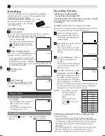
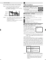
Page 9: ...ess STOP or turn off the power The Instant Timer Recording feature provides a simple and convenient way to make a timed recording EXAMPLE Instant Timer Recording for 30 minutes When a TV is connected with an audio video cable turn the TV on and select the video input mode on the TV Load a cassette tape with the erase prevention tab intact The clock display will change in the counter display Press ...

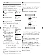
Page 10: ...recording of up to 8 programs within 1 month ENTER MENU MENU TIMER REC SET AUTO REPEAT ON OFF ON OFF SAP CH SETUP SYSTEM SETUP DATE START END CH ENTER CANCEL MENU DATE START END CH 26 SU ENTER CANCEL MENU DATE START END CH 26 SU 11 00PM 11 30PM 125 EP ENTER CANCEL MENU DATE START END CH 26 SU 11 00PM 11 30PM 125 EP ENTER CANCEL MENU When setting the date in step 3 in the Setting the Timer Recordin...

Page 11: ...een for about 4 seconds and the program can be viewed or recorded in stereo The Hi Fi STEREO recording procedure is the same as for normal recordings NOTE When using a CATV system stereo TV programs may be transmitted over a mono cable channel In this case the word STEREO will not appear and the sound will be in mono OUTPUT SELECTION The VHS Hi Fi audio system permits high fidelity recording of MT...

Page 12: ...al connect the audio output connector on the playback VCR to the left audio input connector on this VCR Load cassettes Insert the playback cassette into the playback VCR and the cassette to be recorded on into the recording VCR Select input mode on recording VCR Select the correct external input on the recording VCR On this VCR when using this VCR as the recording VCR Select L when connecting the ...

Page 13: ... VCR indicator is not lit The erase prevention tab of the video cassette is broken off INPUT is set to the LINE mode SYMPTOM CAUSE POSSIBLE SOLUTION The AC power cord is not connected Connect the AC power cord to the AC outlet Connect it correctly Reconnect the antenna cable Set it to CH 3 or 4 Set the TV channel selector to the 3 or 4 position Press the TV VCR selector button The VCR indicator wi...

Page 14: ...ifications subject to change without notice Specifications AC 120 V 60 Hz 9 W 1 7 W 5 C to 40 C 41 F to 104 F 20 C to 60 C 4 F to140 F Horizontal only 360 mm x 95 mm x 222 5 mm 14 3 16 x 3 3 4 x 8 3 4 3 2 kg 7 1 lbs VHS NTSC standard 210 min with ST 210 video cassette 630 min with ST 210 video cassette NTSC type color signal and EIA monochrome signal 525 lines 60 fields DA 4 Double Azimuth head he...

Page 15: ...mounting systems 3 Operational adjustments covered in the Owner s Manual normal maintenance including head cleaning 4 Damage that occurs in shipment due to act of God and cosmetic damage 5 Signal reception problems and failures due to line power surge 6 Products used for commercial purposes including but not limited to rental 7 Accessories 8 Batteries except that Rechargeable Batteries are covered...

Page 16: ...RTERS JVC SERVICE ENGINEERING COMPANY OF AMERICA DIVISION OF JVC AMERICAS CORP 10 New Maple Avenue Pine Brook NJ 07058 9641 JVC FOR SERVICING Only in U S A WARRANTY REPAIR REPLACEMENT FORM PLEASE COMPLETE THE FOLLOWING PLEASE NOTE P O BOXES ARE NOT ACCEPTABLE NAME __________________________________________________________________ STREET ADDRESS _____________________________________________________...

Reviews: