background image

SERVICE MANUAL

No.82852

April 2001

HR-J3008UM/J4008UM

VIDEO CASSETTE RECORDER

Regarding service information other than these sections, refer to the HR-A37U service manual (No.82836). 
Also, be sure to note important safety precautions provided in the service manual.

SPECIFICATIONS

 (The specifications shown pertain specifically to the model HR-J4008UM)

Specifications shown are for SP mode unless specified otherwise.
E. & O.E. Design and specifications subject to change without 
notice.

GENERAL

Power requirement

: AC 110 V – 220 V

d

, 50 Hz/60 Hz

Power consumption

Power on

: 14 W

Power off

: 2.0 W

Temperature

Operating

: 5

°

C to 40

°

C

Storage

: –20

°

C to 60

°

C

Operating position

: Horizontal only

Dimensions (W x H x D) : 360 mm x 94 mm x 247 mm
Weight

: 3.0 kg

Format

: VHS NTSC standard

Maximum recording time

SP

: 210 min. with ST-210 video cassette

EP

: 630 min. with ST-210 video cassette

VIDEO/AUDIO

Signal system

: NTSC-type color signal and EIA 

monochrome signal, 525 lines/
60 fields

Recording/Playback 
system

: DA-4 (Double Azimuth) head helical 

scan system

Signal-to-noise ratio

: 45 dB

Horizontal resolution

: 230 lines

Frequency range

: 70 Hz to 10,000 Hz

Input/Output

: RCA connectors (IN x 1, OUT x 1)

TUNER

Tuning system 

: Frequency-synthesized tuner

Channel coverage

VHF

: Channels 2–13

UHF

: Channels 14–69

CATV

: 113 Channels

RF output

: Channel 3 or 4 (switchable; preset to 

Channel 3 when shipped) 75 ohms, 
unbalanced

TIMER

Clock reference

: Quartz

Program capacity

: 1-year programmable timer/

8 programs

Memory backup time

: Approx. 6 months

Estimated figure based on supplied 
fresh battery; actual performance may 
differ.

ACCESSORIES

Provided accessories

: RF cable (F-type),

Lithium battery CR2025,
Infrared remote control unit,
“AA” battery x 2,
Conversion plug

Summary of Contents for HR-J3008UM

Page 1: ...ndard Maximum recording time SP 210 min with ST 210 video cassette EP 630 min with ST 210 video cassette VIDEO AUDIO Signal system NTSC type color signal and EIA monochrome signal 525 lines 60 fields Recording Playback system DA 4 Double Azimuth head helical scan system Signal to noise ratio 45 dB Horizontal resolution 230 lines Frequency range 70 Hz to 10 000 Hz Input Output RCA connectors IN x 1...

Page 2: ...ole position 2 18 4 CHARTS AND DIAGRAMS 4 1 MAIN SYSCOM AND LT BATTERY SCHEMATIC DIAGRAMS 4 1 4 2 MAIN CIRCUIT BOARD MAIN PWB LPB10130 001C HR J4008UM 4 3 4 3 MAIN CIRCUIT BOARD MAIN PWB LPB10130 001D HR J3008UM 4 5 5 PARTS LIST 5 1 PACKING AND ACCESSORY ASSEMBLY M1 5 1 5 2 FINAL ASSEMBLY M2 5 2 5 3 MECHANISM ASSEMBLY M4 5 4 5 4 ELECTRICAL PARTS LIST 5 6 MAIN BOARD ASSEMBLY 03 5 6 A C HEAD BOARD A...

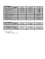
Page 3: ...17 POWER CORD QMP73J0 170 518 CLEANER ASSEMBLY LP40369 001D 518A CLEANER ROLLER PQ46418 1 2 518B CLEANER PQ46419 1 2 518C CLEANER ARM LP30407 001D 520 CAP LP30336 001A 531 SCREW REAR QYTDSF3010M 532 SCREW TERMINAL BOARD QYTDSF3010Z HR J4008UM Note Mark is not used Mark is same as left Mark reference model was also changed MAIN BOARD ASSEMBLY 03 REF NO MODEL HR A37U HR J3008UM ITEM PW1 MAIN BOARD A...

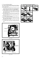
Page 4: ...ch is loaded be cause of any electrical failure manually remove it by taking the following steps 1 Unplug the power cord plug from the power outlet 2 Refer to the disassembly procedure and perform the dis assembly of the major parts before removing the drum assembly 3 Unload the pole base assembly by manually turning the loading motor of the mechanism assembly toward the front In doing so hold the...

Page 5: ... 1 3d 4 In the same way as in the electrical failure instructions in 2 1 3 1 5 remove the top guide 5 Raise the cassette tape cover By keeping it in that posi tion draw out the cassette tape case from the cassette holder and take out the tape 6 By hanging the pinch roller arm assembly spring back on the hook take up the slack of the tape into the cas sette Fig 2 1 3d Fig 2 1 3c Pole base assembly ...

Page 6: ...d Press lever assembly Lid guide Guide arm assembly Reel disk take up side Sub brake assembly take up side Main brake assembly take up side Idler arm assembly Idler lever Main brake assembly supply side Reel disk supply side Rec safety lever Tension brake assembly Adjust pin Tension arm assembly Pole base assembly supply side Full erase head Pole base assembly take up side T1 T26 T25 T24 T23 T22 T...

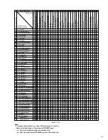
Page 7: ...y as this will cause damage to the video head 2 To clean the parts of the tape transport system other than the upper drum use a piece of closely woven cloth or a cotton swab soaked with alcohol 3 After cleaning make sure that the cleaned parts are com pletely dry before using the video tape 3 Lubrication With no need for periodical lubrication you have only to lu bricate new parts after replacemen...

Page 8: ...1 2 2 11 Clutch unit B 1 2 2 12 Change lever assembly B 3 2 2 12 Direct gear B 4 2 2 12 Coupling gear B 5 2 2 12 Clutch gear B 6 2 2 13 Link lever B 1 2 2 14 Cassette gear B 2 2 2 14 Control cam B 2 2 2 14 Worm gear B 1 Lid guide T B 5 2 2 15Control bracket1 B 1 2 2 15Control plate B 6 2 2 16Loading arm gear supply side B 7 2 2 16Loadingarmgear take upside B 8 2 2 16Loading arm gear shaft B 9 2 2 ...

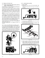
Page 9: ...ration in response to phases of the rotary encoder internal switch positions the mechanism may not operate properly unless such parts as the rotary encoder control plate loading arm gear control cam cassette gear limit gear relay gear and drive gear are installed in their correct posi tions Especially this model is not provided with any cassette hous ing assembly so that cassette loading and unloa...

Page 10: ...y into the groove See Fig 2 2 3g 4 While swinging the lock lever R of the cassette holder assembly toward the front put the legs A and B into the rail See Fig 2 2 3g 5 Drop the three legs on the left side of the cassette holder assembly into the groove at one time See Fig 2 2 3h 6 Slide the whole cassette holder assembly toward the front to bring it to the eject end position 7 Install the limit ge...

Page 11: ...replacing only the A C head remove the three screws B while controlling the compression spring Fig 2 2 6a Fig 2 2 6c Fig 2 2 4a 2 2 5 Guide arm assembly and press lever assembly 1 How to remove 1 Remove the spring and expand the lug of the lid guide in the arrow indicated direction Then remove the guide arm assembly by pulling it up 2 Remove the press lever assembly by pulling it up See Fig 2 2 5a...

Page 12: ...mbly are correctly in stalled as indicated in Fig 2 2 8b 3 Making sure that the connector for the capstan motor is correctly mounted and securely tighten the three screws A Note When the capstan motor has been replaced with a new one perform recording in the EP or LP mode for at least 2 minutes at normal temperatures immediately be fore starting the FF REW or SEARCH operations Ag ing Spacer Spacer...

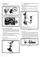
Page 13: ...he rotary encoder guide in the arrow indicated direction and remove the change lever assembly 2 Remove the slit washer retaining the direct gear and re move the latter Take care so as not to lose the washer and spring See Fig 2 2 12a 2 2 10 Rotary encoder 1 How to remove 1 Remove the screw A and remove the rotary encoder by pulling it up See Fig 2 2 10a Fig 2 2 10a Rotary encoder Front side Screw ...

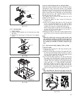
Page 14: ...t of the rotary encoder guide Mark E Fig 2 2 13c Worm gear Control cam Main deck guide hole Control cam guide hole Cassette gear 2 2 14 Cassette gear control cam and worm gear 1 How to remove 1 Remove the control cam by lifting it 2 Open the two lugs of the cassette gear outward and pull the latter off 3 Remove the belt wound around the worm gear and the loading motor 4 Open the lug of the lid gui...

Page 15: ...embly shaft Section D Section D Section A Hole A 3 Install the control plate so that the section A of the load ing arm gear shaft fits into the hole A of the control plate the section B of the control plate guide into the hole B and the control plate comes under the section C of the rotary encoder guide and the section D of the loading arm gear shaft while press fit the pole base assmebly sup ply ...

Page 16: ...e main deck 3 Remove the lugs B and C of the sub brake assembly take up side from the main deck and remove the sub brake assembly take up side Fig 2 2 19a Spring Sub brake assembly take up side Lug B Lug A Lug C Fig 2 2 20a Lug D Lug C Spring Lug E Lug A Lug B Main brake assembly take up side Reel disk take up side Main brake assembly supply side Notch 2 2 20 Main brake assembly take up side reel ...

Page 17: ...2 Remove the reel disk supply side by loosening in the arrow indicated direction the main brake assembly sup ply side 3 Remove the tension spring on the back of the main deck Then release the lug of the tension arm bearing in the arrow indicated direction and draw out the tension arm assembly See Fig 2 2 21a Fig 2 2 21a Lugs Tension brake assembly Lug of the tension arm bearing Reel disk supply si...

Page 18: ...stall a new washer and upper drum assembly on the drum shaft See Fig 2 2 25a 3 Install the cap to the upper drum assembly 4 Position the collar assembly as indicated in Fig 2 2 25c while controlling its up down movement 5 Secure the collar assembly in position with a hexagonal wrench while pressing its top with the fingers 6 After installation gently turn the upper drum assembly with your hand to ...

Page 19: ...e Fig 2 3 1a 5 Reduce the V PB FM waveform by the tracking opera tion If a drop in level is found on the left side turn the guide roller of the pole base assembly supply side with the roller driver to make the V PB FM waveform linear If a drop in level is on the right side likewise turn the guide roller of the pole base assembly take up side with the roller driver to make it linear See Fig 2 3 1c ...

Page 20: ...scope Measuring point D TP106 PB FM External trigger E TP111 D FF Adjustment part F A C head base Mechanism assembly Specified value G Maximum V PB FM waveform Adjustment tool H A C head positioning tool PTU94010 1 Play back the alignment tape A1 2 Apply the external trigger signal to D FF E to observe the V PB FM waveform at the measuring point D 3 Set the VCR to the manual tracking mode 4 Loosen...

Page 21: ...point D TP106 PB FM External trigger E TP111 D FF Adjustment part F Jig RCU Code 50 Specified value G STOP mode Maximum V PB FM waveform Adjustment tool H Jig RCU PTU94023B 2 3 5 Tension pole position 1 Play back the back tension cassette gauge A 2 Check that the indicated value on the left side gauge is within the specified value G 3 If the indicated value is not within the specified value G perf...

Page 22: ...304 2 320 4 335 IN FF REW OUT PLAY Direct gear Change lever 2 ON HALF REV HALF FF REW OFF Tension arm ON CONTACT OFF Main brake S ON CONTACT OFF Main brake T ON OFF Sub brake S ON OFF Sub brake T ON OFF OFF ON Capstan brake ON OFF Rec safety switch Operation mode ON PLAY ON REV CONTACT OFF C INS Pinch roller SUPPLY CENTER TAKE UP Idler position READY RESET Take up lever ON OFF Guide arm Timer REC ...

Page 23: ......

Page 24: ...VICTOR COMPANY OF JAPAN LIMITED VIDEO DIVISION Printed in Japan S40894 ...

Reviews: