background image

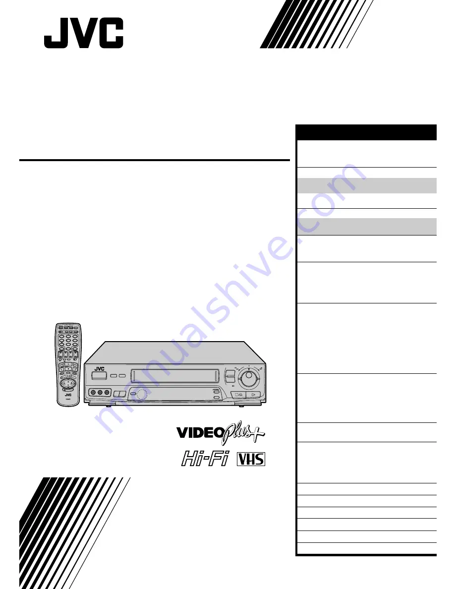
HR-J635EK

VIDEO CASSETTE RECORDER

INSTRUCTIONS

PU30425-1790-2

TM

PAL

FF

REW

SHUTTLE

AUTO SP / LP

TIMER

TIMER

VIDEO(MONO)L–AUDIO–R

SP/LP

– TV PROG. +

OPERATE

AUDIO 

DUBBING

TV PROG /

JOG

6

q

R.A.EDIT

IN / OU

T

STAR

T

SCE

NE FIN

DER

PROG CHE

CK

TV VOL.

OPERATE

MODE

CLOCK

CH SET

C.MEMORY

DISPLAY

DAILY

AUX

ADD TIME

C.RESET

CANCEL

DATE

STOP

START

AUDIO MONITOR

(MONITOR)

TV/VIDEO

TV

VCR

TIMER

WEEKLY

A

1

2

4

5

3

6

8

0

7

9

B

PUSH JOG

MULTI BRAND

REMOTE CONTROL UNIT

TV

PROG.

PRO

G

OK

EXPRESS PROGRAMMING

STORE

2

1

3

ILLUMI GUIDE

SAFETY FIRST

2

Safety Precautions .................................... 2
Some Do’s And Dont’s ............................. 3

INSTALLING YOUR NEW RECORDER

4

Basic Connections ................................... 4
Tune The TV To Your Video Recorder ...... 5
Connection To A Satellite Receiver .......... 6
Connection To A Stereo System ............... 7

INITIAL SETTINGS

8

Tuner Set .................................................. 8
Clock Set ................................................. 9

PLAYBACK

11

Basic Playback ....................................... 11
Playback Features .................................. 12

RECORDING

20

Basic Recording ..................................... 20
B.E.S.T. Picture System ........................... 21
On-Screen Displays ............................... 23
Recording Features ................................ 24

TIMER RECORDING

26

Information On Video Plus+ .................. 26

Guide Channel Set .............................. 26

Video Plus+ Timer Recording ................. 28
Regular Timer Programming .................. 30

Check And Cancel Programmes .......... 32
Timer Warning .................................... 32
Auto SP/LP Timer ................................. 33
PDC Recording ................................... 33

EDITING

34

Edit To Or From Another Video
Recorder ................................................ 34
Edit From A Camcorder ......................... 35
Random Assemble Editing ..................... 36
Audio Dubbing ...................................... 38

REMOTE CONTROL

40

Multi-Brand Remote Control .................. 40

USING THE CONFIRMATION SCREEN

41

Storing Channels Manually .................... 41
Delete A Channel .................................. 42
Change Station Preset Position ............... 42
Set Stations ............................................ 43

TV STATION AND ID LIST

45

TV STATION CHANNEL NUMBER GUIDE

46

TROUBLESHOOTING

47

QUESTIONS AND ANSWERS

49

INDEX

50

SPECIFICATIONS

55

CONTENTS

Summary of Contents for HR-J635EK

Page 1: ... 6 Connection To A Stereo System 7 INITIAL SETTINGS 8 Tuner Set 8 Clock Set 9 PLAYBACK 11 Basic Playback 11 Playback Features 12 RECORDING 20 Basic Recording 20 B E S T Picture System 21 On Screen Displays 23 Recording Features 24 TIMER RECORDING 26 Information On Video Plus 26 Guide Channel Set 26 Video Plus Timer Recording 28 Regular Timer Programming 30 Check And Cancel Programmes 32 Timer Warn...

Page 2: ...t switches operating current on and off IMPORTANT Connection to the mains supply in the United Kingdom DO NOT cut off the mains plug from this equipment If the plug fitted is not suitable for the power points in your home or the cable is too short to reach a power point then obtain a proper safety approved extension lead adapter or consult your dealer BE SURE to replace the fuse only with an ident...

Page 3: ...or has a standby mode Switch off using the switch on the equipment and make sure that your family knows how to do this Special arrangements may need to be made for infirm or handicapped people DON T use equipment such as personal stereos or radios so that you are distracted from the requirements of road safety It is illegal to watch television whilst driving DON T listen to headphones at high volu...

Page 4: ...ed RF cable between the RF OUT jack on the rear panel of the recorder and the TV s aerial terminal Before operating the recorder make sure the TV s preset is set to the VIDEO preset AV CONNECTION To Connect To A TV With AV Input Terminals a Connect the aerial recorder and TV as per RF CONNECTION b Connect the provided SCART cable between the AV1 IN OUT socket on the rear panel of the recorder and ...

Page 5: ... use with a video recorder or to a spare preset if there is not a specified video preset on your TV RESET OUTPUT MODE 4 Return the RF OUT switch to ON NOTE If some interference noise is continually seen on the screen consult your JVC dealer The video recorder sends picture and sound signals via the RF connecting cable to your TV on UHF channel 36 If you have connected the video recorder to your TV...

Page 6: ...ecorder allows simple connection to a satellite receiver NOTES When connecting your recorder to a TV equipped with 21 pin SCART connectors follow the illustration above using the cables shown in gray For details check your satellite receiver s instruction manual Outdoor Unit Satellite Cable Satellite Receiver Unit TV Aerial cable Aerial Mains outlet Back of TV 21 pin SCART connectors ANT IN RF OUT...

Page 7: ...ystem turn the TV s volume down completely CAUTIONS This recorder has a dynamic range of more than 80 dB with regards to its Hi Fi audio capability It is recommended that you check the maximum level if you are going to listen to the Hi Fi audio signals through a stereo amplifier A sudden surge in the input level to the speakers may damage them Some speakers and televisions are specially shielded t...

Page 8: ...the necessary mode for this procedure so simply press OK to enter the selection The Auto Ch Set screen appears and remains on screen while the recorder searches for receivable stations VIEW CONFIRMATION SCREEN 4 The stations your recorder located appear on a Confirmation screen preset positions PR presets CH and station names ID Z pg 45 To view the next page of the listing press PUSH JOG fi The bl...

Page 9: ...lock off the accuracy of your recorder s built in clock may be reduced which could adversely effect timer recording Both Auto and Manual clock setting procedures begin from step 3 TURN THE RECORDER ON 1 Press OPERATE ACCESS CLOCK SET SCREEN 2 Press CLOCK on the remote control The Clock Set screen appears Preparation 1 2 4 5 3 6 8 0 7 9 2 1 3 OPERATE OPERATE OK C L O C K CLOCK SET TIME DATE YEAR 0 ...

Page 10: ...ERATION 6 Press CLOCK NOTES Just Clock when set to ON enables adjustment of the recorder s built in clock every hour on the hour except for 11 o clock in the evening and midnight Just Clock is not effective when the recorder s power is on unless the recorder is tuned to the same preset selected in the Clock Set screen the recorder is in the Timer mode a difference of more than 3 minutes exists bet...

Page 11: ...e left and release it To go forward press FF or turn the SHUTTLE ring to the right and release it START PLAYBACK 3 Press PLAY BEST appears blinking in the recorder s display panel for 5 seconds Z pg 22 Playback picture quality of LP recordings will not be as high as SP recordings STOP PLAYBACK 4 Press STOP on the remote or STOP EJECT on the recorder s front panel Then press STOP EJECT to remove th...

Page 12: ...OG dial to the right for forward frame by frame playback or to the left for reverse frame by frame playback OR Press PAUSE OR Press PUSH JOG or To resume normal playback press PLAY Slow Motion ACTIVATE SLOW MOTION PLAYBACK 1 During playback or still turn the SHUTTLE ring to the right for forward slow motion or to the left for reverse slow motion refer to the illustration above OR During still pict...

Page 13: ...Y High Speed Turbo Search ACTIVATE HIGH SPEED SEARCH 1 During playback or still turn the SHUTTLE ring all the way to the right for forward high speed search or to the left for reverse high speed search For forward search with a visible picture turn the SHUTTLE ring all the way to the right and release it within 1 second For reverse search with a visible picture turn the SHUTTLE ring all the way to...

Page 14: ...ve several programmes recorded you can easily access any of them NOTE Before starting make sure that the recorder is off and that the Timer mode is disengaged ACTIVATE INSTANT REVIEW 1 Press REVIEW The recorder power comes on and the recorder searches for the index code indicating the start of the last timer recorded programme Once it s found playback begins automatically The front display panel t...

Page 15: ...er the tape is fully rewound Before starting make sure the recorder is in the Stop mode For Automatic Power Off After Tape Rewind press REW then press OPERATE within 2 seconds NOTE If you want the power to be turned off automatically when the counter reads 0 00 00 instead of at the beginning of the tape press C MEMORY so that the M mark appears before pressing REW Tape Position Indicator The tape ...

Page 16: ...f B from the current position press PUSH JOG twice To locate the beginning of D from the current position press PUSH JOG once When the specified index code is located playback begins automatically 2 Current position Index number Tape Remaining Time DISPLAY REMAINING TIME 1 Press DISPLAY until the time remaining on the tape appears By pressing the DISPLAY button you can change the display to show t...

Page 17: ...ound instead Scene Finder does not function during Index Search This function helps you check contents of unlabeled recorded tapes at the touch of a single button NOTE Scene Finder cannot be used when the recorder is in the Record mode Scene Finder 10 minutes on counter FF REW FF REW FF REW Search Search Search 5 seconds 10 minutes on counter 5 seconds 5 seconds SHUTTLE SCENE FINDER S T O P Counte...

Page 18: ...f superimposed displays may be cut off during NTSC playback 1 2 4 5 3 6 8 0 7 9 2 AUDIO MONITOR P L A Y Soundtrack Selection Your video recorder is capable of recording three soundtracks HI FI L HI FI R and NORM and will play back the one you select During Playback Pressing AUDIO MONITOR on the remote control changes the soundtrack being played back as follows TRACK Recorder s Front Panel On Scree...

Page 19: ...because your video recorder is initially set to respond to A code signals You can easily modify your video recorder to respond to B code signals REMOVE POWER SUPPLY 1 Unplug the mains power cord from the mains outlet SET A B CODE SWITCH 2 Set to B RE SUPPLY POWER 3 Plug the mains power cord back into the mains outlet TURN THE RECORDER ON 4 Press OPERATE on the remote control The recorder will now ...

Page 20: ...splay panel to confirm the selected tape speed Picture quality of LP recordings will not be as high as SP recordings START RECORDING 4 Press and hold RECORD and PLAY on the remote control or press RECORD on the recorder PAUSE RESUME RECORDING 5 Press PAUSE Press PLAY to resume recording STOP RECORDING 6 Press STOP on the remote control or STOP EJECT on the recorder Then press STOP EJECT to remove ...

Page 21: ...ult setting is ON If this is the case go to step 4 If not press PUSH JOGfi to place the pointer next to B E S T then press PUSH JOG to set to ON CLOSE MODE SELECT SCREEN 4 Press MODE START RECORDING 5 Press and hold RECORD and PLAY on the remote or RECORD on the recorder The recorder spends approximately 7 seconds assessing the condition of the tape then begins recording When the BEST indicator be...

Page 22: ...D PAUSE mode The recorder then automatically checks the condition of the tape and after approximately 7 seconds re enters RECORD PAUSE 2 Press PLAY to start recording If you want to bypass the B E S T system and begin recording immediately set B E S T to OFF in step 3 on page 21 Playback The recorder assesses the quality of the tape once you initiate playback When watching a tape recorded with B E...

Page 23: ...SELECT SCREEN 5 Press MODE 6 q 1 2 4 5 3 6 8 0 7 9 2 1 3 The superimposed indication on the TV screen tells you what the recorder is doing 1 Operation mode indicators 2 Preset position number and station name Aux indicator AUX1 AUX2 or F AUX 3 Cassette loaded mark 4 Tape speed SP LP EP EP is for NTSC playback only 5 Clock display 6 Current day month year 7 NICAM display 8 Tape direction 9 Tape pos...

Page 24: ...a channel broadcasting a monaural programme NICAM appears on screen for a few seconds NOTES ON SCREEN must be set to ON or the on screen displays will not appear Z pg 23 Bilingual programmes are not currently broadcast in the U K 1 2 4 5 3 6 8 0 7 9 2 1 3 6 q PUSH JOG TV PROG AUDIO MONITOR TV PROG To Record NICAM Stereo And Bilingual Programmes The NICAM audio programme will be recorded on the Hi ...

Page 25: ...ecord for more than 30 minutes press RECORD to extend the time Each press extends recording time by 30 minutes NOTE You can only perform ITR using the RECORD button on the recorder s front panel Elapsed Recording Time Indication You can check the exact time of a recording SET COUNTER DISPLAY 1 Press DISPLAY until a counter reading appears on the dispay panel RESET COUNTER 2 Press C RESET before st...

Page 26: ...age 9 After setting the Guide Channel the station names and preset positions may be incorrect if you stored or skipped channels In this case re perform Guide Channel setting 6 q 1 2 4 5 3 6 8 0 7 9 2 1 3 OK NUMBER CH SET CANCEL Guide Channel Set MAKE LIST OF STORED STATION NAMES AND PRESET POSITIONS 1 Ex ACCESS CH SET MODE MENU SCREEN 2 Press and hold CH SET for over 2 seconds The Ch Set Mode Menu...

Page 27: ...ber Repeat steps 4 and 5 as necessary CLOSE MENU 6 Press CH SET and selection is complete If you already know the Guide Channel number for a station 1 After step 3 press PUSH JOG GUIDE CH begins blinking 2 Enter the Guide Channel number using the NUMBER keys or PUSH JOG fi then press PUSH JOG TV PROG begins blinking 3 Enter the preset position using the NUMBER keys or PUSH JOG fi then press PUSH J...

Page 28: ... beginning If for some reason the remote control s signal is not received by the video recorder press CANCEL and re perform the timer programming procedure from the beginning TIMER PROGRAMMING 0 9 VIDEO PLUS EXPRESS PROGRAMING CANCEL EXIT ACCESS TIMER PROGRAM MING SCREEN 1 Press PROG The front display panel looks like this If you are using the Illumi Guide feature the following buttons will light ...

Page 29: ...nsate for anticipated programme schedule delays this way To Timer Record Weekly Or Daily Serials after pressing OK in step 3 press WEEKLY NUMBER key 9 for weekly serials or DAILY NUMBER key 8 for daily serials Monday Friday You can programme this recorder to timer record as many as 8 programmes If you try to programme the recorder to record a ninth PROGRAM FULL appears on screen and FULL appears o...

Page 30: ...or some reason the remote control s signal is not received by the video recorder press CANCEL and re perform the timer programming procedure from the beginning TIMER RECORDING cont CANCEL ILLUMI GUIDE 6 q Remember the clock must be set before you can progamme the timer Z pg 9 ACCESS TIMER PROGRAM MING SCREEN 1 Press PROG If you are using the Illumi Guide feature the following buttons will light up...

Page 31: ...T STOP 21 00 22 00 SP ON DATE TV PROG 25 12 1 BBC1 SET OK SP M D 6 q 1 2 4 5 3 6 8 0 7 9 2 1 3 OK WEEKLY TIMER D A I L Y TV PROG SP LP SP LP 7 7 8 TIMER 4 5 S T O P D A T E PDC NOTES For safety your recorder disables all other functions while in the Timer mode If you want to use the recorder but its Timer mode is engaged press TIMER and all other functions are operable To re engage the timer press...

Page 32: ... TO START SOON CANCEL 6 q 1 2 4 5 3 6 8 0 7 9 2 1 3 OK CANCEL START TV PROG D A T E PROG CHECK STOP ACCESS PROGRAMME SCREEN 1 Press PROG CHECK Each time you press the next program s information appears Press OK and watch the front display panel as the Start and Stop times the Date and the Preset appear If the recorder is turned on and the TV is set to its VIDEO mode you can check program informati...

Page 33: ...ut number may not match the actual number of programmes that have been timer recorded Z pg 14 A U T O S P L P T I M E R ENGAGE AUTO SP LP TIMER 1 Press AUTO SP LP TIMER on the recorder front panel The button lights green For Example Recording a program of 210 minutes in length onto a 180 minute tape Make sure you press AUTO SP LP TIMER before performing timer programming NOTES The Auto SP LP Timer...

Page 34: ...ORDING DECK S INPUT MODE 2 Set to AUX With this video recorder press NUMBER key 0 and or TV PROG to select depending on the connector being used AU 1 for the AV1 IN OUT connector or AU 2 for the AV2 IN connector START SOURCE PLAYER 3 Engage its Play mode START RECORDING DECK 4 Engage its Record mode NOTE All necessary cables can be obtained from your dealer 1 2 4 5 3 6 8 0 7 9 2 1 3 TV Receiver TV...

Page 35: ...ion manual for operating procedure SET RECORDER S INPUT MODE 2 Press NUMBER key 0 F AU appears in place of a preset number START CAMCORDER 3 Engage its Play mode START RECORDER 4 Engage its Record mode NOTE Connections made to the front panel AUDIO VIDEO input connectors automatically override those made to the rear panel AUDIO VIDEO input connectors 1 2 4 5 3 6 8 0 7 9 2 1 3 NUMBER 0 6 q Player E...

Page 36: ...PARE FOR EDITING 2 Insert the cassette to be recorded on into the recorder and set the recorder s input mode LOAD SOURCE CASSETTE 3 Insert the source cassette into your recorder START SOURCE PLAYBACK 4 Press PLAY ACCESS R A EDIT FUNC TION 5 Press R A EDIT The screen is superimposed on the video playback in step 6 LOCATE EDIT IN POINT 6 Find the point on the source tape from where you want the edit...

Page 37: ...ccupied by timer recording data those spaces cannot be used to register edit in and out points meaning you won t be able to edit 8 scenes When all 8 programs are full PROGRAM FULL appears on the R A EDIT screen To cancel a program see page 32 RM V704U Multi Brand R A Edit Controller Not provided By connecting this controller to your recorder s R A EDIT connector you can perform Random Assemble Edi...

Page 38: ... tape in your recorder and press PAUSE when you find the point where you want to start dubbing ENGAGE AUDIO DUBBING 4 Press AUDIO DUBBING To perform audio dubbbing with audio mixing press AUDIO MONITOR to select L R at this point Audio dubbing with audio mixing is not possible if you re using a monaural audio component or if you don t have an audio mixer START DUBBING 5 Engage the audio component ...

Page 39: ...ubbing Audio dubbing is also possible using the rear panel AV1 IN OUT or AV2 IN connectors When using these connectors make sure to select the correct input mode in step 2 Connections made to the recorder s front panel are given priority over those made to the rear panel connectors Audio dubbing cannot be performed on a cassette that has had its record safety tab removed When playing back an audio...

Page 40: ...as well as many other models it may not work with your TV or in some instances may have limited function capability Control Your TV Using Addi tional Buttons The NUMBER keys on the remote can also be used to select the TV s preset by setting the remote control to the TV mode 1 Set the TV VCR switch to TV 2 Use the NUMBER keys and the Digit Entry SP LP button the PUSH JOG button the DISPLAY button ...

Page 41: ... The Manual Ch Set screen appears INPUT CHANNEL 4 The number 21 appears blinking to the right of CH Press the NUMBER keys to input the preset number of the channel you want to store Although CH is set to 21 when the Manual Ch Set screen appears to store channel 21 you must select 21 using the NUMBER keys For fine tuning adjustment press PUSH JOG until the item under CH begins blinking then press P...

Page 42: ...ATION SCREEN 3 Press CH SET Change Station Preset Position SELECT ITEM 1 Press PUSH JOG fi until the item you want to move begins blinking Then press OK and the station name ID and its preset CH number begin blinking SELECT NEW POSITION 2 Press PUSH JOG fi to move the station to the new preset position then press OK Example If you moved the station in position 3 to position 7 the stations original...

Page 43: ...USH JOG fi SWITCH STATIONS 3 Press OK Repeat steps 1 through 3 as necessary CLOSE CONFIRMATION SCREEN 4 Press CH SET SELECT STATION NAME CHARACTER 2 Press PUSH JOG and the first letter of the station name begins blinking ENTER NEW CHARACTER 3 Press PUSH JOG fi to cycle through the characters A Z 0 9 space and stop when the desired one is indicated then press PUSH JOG to enter Enter the remaining c...

Page 44: ... 1 Press PUSH JOG fi until the channel you want to tune begins blinking ACCESS MANUAL CH SET SCREEN 2 Press OK three times The Manual Ch Set screen appears PERFORM TUNING 3 Press PUSH JOG fi until the picture is its clearest Then press OK The Confirmation screen appears Repeat steps 1 through 3 as necessary CLOSE CONFIRMATION SCREEN 4 Press CH SET PUSH JOG USING THE CONFIRMATION SCREEN cont ...

Page 45: ...2 ORF2 ORF3 ORF3 OWL 3 OWL3 Premiere PRM1 PR07 PR07 RAI1 RAI1 RAI2 RAI2 RAI3 RAI3 RB1 RB1 RB3 RB3 Rikisutvarpid S RKPS RTBF 1 RTB1 RTBF 2 RTB2 STATION NAME ID RTE 1 RTE1 RTL RTL RTL 2 RTL2 RTP RTP SAT SAT 1 SAT1 Scottish TV SCOT SC4 SC4 SDR SDR SDR1 SDR1 SFB1 SFB1 SFB3 SFB3 SKY Sky One SKY1 Sky Net SKYN Sport SPRT SR 1 SR1 Super RTL SRTL STV Test STVT STV 1 STV1 STV 2 STV2 Suedwest3 SW3 SWF 1 SWF1...

Page 46: ...ge Hill 22 28 25 32 Sutton Coldfield 46 40 43 50 The Wrekin 26 33 23 29 Waltham 58 64 61 54 North Belmont 22 28 25 32 Emley Moor 44 51 47 41 BBC1 BBC2 ITV CH4 North West Caldbeck 30 34 28 32 Winter Hill 55 62 59 65 North East Bilsdale West Moor 33 26 29 23 Chatton 39 45 49 42 Pontop Pike 58 64 61 54 Scotland Angus 57 63 60 53 Black Hill 40 46 43 50 Sandale 22 Caldbeck 34 28 32 Creigkelly 31 27 24 ...

Page 47: ...back picture is blurred or interrupted while TV broadcasts are clear PLAYBACK POSSIBLE CAUSE If you re using the RF OUT connec tion the TV receiver s preset selector is set to the wrong video preset the RF switch has been mistak enly set to OFF If you re using the AV connection the TV receiver is not set to the AV mode This is normal The automatic tracking mode is engaged The automatic tracking mo...

Page 48: ...le 3 and on the display panel won t stop blinking 4 The cassette is automatically ejected and and on the display panel won t stop blinking 5 blinks for 10 seconds and the Timer mode is disengaged 6 The cassette is automatically ejected the power shuts off and and won t stop blinking 7 Video Plus does not timer record properly POSSIBLE CAUSE The clock and or the timer have been set incorrectly The ...

Page 49: ...e a recording the end of the recording before the pause is overlapped by the beginning of the continuation of recording Why does this happen A This is normal It reduces distortion at the pause and resume points Q Can the video recorder indefinitely remain in the Record Pause mode A No The video recorder shuts off automatically after 5 minutes to protect the heads Q What happens if the tape runs ou...

Page 50: ... Z pg 2 High Seed Search Z pg 13 I Illumi Guide Z pg 28 Index Code Z pg 16 Index Search Z pg 16 Instant ReView Z pg 14 Instant Timer Recording ITR Z pg 25 J Just Clock Z pg 9 Jog Dial Z pg 12 L Load A Cassette Z pg 11 M Manual Channel Set Z pg 41 Manual Clock Set Z pg 10 Manual Tracking Z pg 14 Moisture Condensation Z pg 2 Multi Brand Remote MBR Control Setting Z pg 40 N Next Function Memory Z pg ...

Page 51: ...ctor enables easy connec tion of video output from another recorder or camcorder for editing Z pg 35 VIDEO MONO L AUDIO R FF REW SHUTTLE AUTO SP LP TIMER TIMER SP LP TV PROG OPERATE AUDIO DUBBING TV PROG JOG 6 q 8 4 0 6 10 20dB NORM L 1 2 R SP LP EP M D D I T R W REMAIN 9 0 2 3 4 1 6 5 8 7 0 AUDIO Input Connector L enables easy connection of audio output mono from an other recorder camcorder or ot...

Page 52: ...n on screen selection menus Z pg 27 C RESET Button resets counter to 0 00 00 Z pg 17 8 START Button accesses Program screen inputs of programme Start Time Z pg 30 9 STOP Button inputs programme Stop Time Z pg 31 0 SP LP Button selects tape speed Z pg 20 Digit Entry Button is used in controlling con nected TV Z pg 40 AUDIO MONITOR Button changes output sound mode Z pg 18 TV Mute Button mutes sound ...

Page 53: ...der Z pg 12 E STOP Button same as button on recorder Z pg 11 R PROG CHECK Button accesses Program screens next program s information screen appears each time button is pressed Z pg 32 IN OUT Button registers edit in and edit out points in memory during R A Edit mode Z pg 36 T OK Button enters selections made in on screen menus Z pg 8 START Button starts automatic editing Z pg 37 Y R A EDIT Button ...

Page 54: ...f UHF channel 36 is used in your area Z pg 5 1 Mains Power Cord supplies power to recorder Z pg 4 2 AUDIO OUT L R Connectors enable connection of audio cassette recorder TV or second video recorder for dubbing Z pg 7 3 AV1 IN OUT SCART Connector enables AV connec tion to TV or second recorder input recordable when AU 1 selected Z pg 4 4 AV2 IN Connector enables connection of satellite receiver or ...

Page 55: ...e ratio 45 dB Horizontal resolution 250 lines Frequency range 70 Hz to 10 000 Hz Normal audio 20 Hz to 20 000 Hz Hi Fi audio Input Output 21 pin scart connector x 2 IN OUT x 1 IN x 1 RCA connector x 1 IN x 1 OUT x 1 TUNER TIMER TV channel storage capacity 99 positions AUX position AU Tuning system Frequency synthesized tuner Channel coverage UHF channels 21 69 470 862 MHz Aerial output UHF channel...

Page 56: ...HR J635EK COPYRIGHT 1996 VICTOR COMPANY OF JAPAN LTD EK Printed in Japan 0396HOV UN VP VICTOR COMPANY OF JAPAN LIMITED ...

Reviews: