1
KS-AX3205D
POWER AMPLIFIER: INSTRUCTIONS
УСИЛИТЕЛЬ МОЩНОСТИ: ИНСТРУКЦИИ ПО ЭКСПЛУАТАЦИИ
1212ATHHACTKK
EN, RU
© 2012 JVC KENWOOD Corporation
ENGLISH
Thank you for purchasing a JVC product.
If you have any questions or require information regarding installation kits, consult your “JVC IN-
CAR ENTERTAINMENT” or a company supplying the kits.
For safety....
s 3TOPTHECARBEFOREPERFORMINGANYCOMPLICATEDOPERATIONS
CAUTIONS AND NOTES
This unit is designed to operate on
12 V DC, NEGATIVE ground electrical systems.
JVC recommends consulting a qualified technician for installation.
s 4HISUNITUSES"4,"ALANCED4RANSFORMERLESS AMPLIlERCIRCUITRYIEmOATINGGROUNDSYSTEM
so comply with the following:
– Do not connect the “
·
” terminals of the speakers to each other.
– Do not connect the “
·
vTERMINALSOFTHESPEAKERSTOTHEMETALBODYORCHASSIS
s #OVERTHEUNUSEDLEADSWITHINSULATINGTAPETOPREVENTTHEMFROMSHORTCIRCUITING
s 7HENANEXTENSIONLEADISUSEDITSHOULDBEASTHICKANDSHORTASPOSSIBLECONNECTITlRMLY
with insulating tape.
s "ESURETOLEAVEANAPPROPRIATESPACEBETWEENTHEANTENNAAERIAL ANDTHEWIRESOFTHISUNIT
s )FTHEFUSEBLOWSlRSTMAKESURETHEWIRESARENTTOUCHINGTOCAUSEASHORTCIRCUITTHENREPLACE
the old fuse with one with the same rating.
s $ONOTLETPEBBLESSANDORMETALLICOBJECTSGETINSIDETHEUNIT
s 4OKEEPTHEHEATDISSIPATIONMECHANISMRUNNINGEFFECTIVELYWIPETHEACCUMULATEDDUSTOFF
periodically.
s ,ISTENINGTOTHETAPERADIO#$ORDIGITALAUDIOPLAYERETCWITHTHEVOLUMESETATAHIGHLEVEL
FORALONGPERIODOFTIMEWILLEXHAUSTTHEBATTERYWHILETHEENGINEISTURNEDOFFORWHILETHE
engine is idling.
s 4HISUNITBECOMESVERYHOT"ECAREFULNOTTOTOUCHTHEUNITNOTONLYWHENUSINGBUTAFTERUSING
$/./4DISASSEMBLETHEUNITSINCETHEREARENOUSERSERVICEABLEPARTSINSIDE
INSTALLATION
4HEFOLLOWINGILLUSTRATIONSHOWSATYPICALINSTALLATION(OWEVERYOUSHOULDMAKEADJUSTMENTS
corresponding to your specific car.
Å
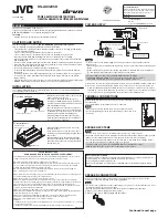
Location of the unit
Under the front seat
Onto the trunk floor
s-OUNTTHISUNITONAFIRMSURFACESUCHASINTHE
trunk or under the front seat.
s3INCEHEATISGENERATEDINTHEUNITDONOT
MOUNTITNEARINFLAMMABLEOBJECTS)NADDITION
mount it in an area that will not prevent the unit
from dissipating the heat.
s$ONOTMOUNTTHEUNITINTHEPLACESSUBJECTTO
heat: near a radiator, in a glove compartment or
in insulated areas such as under a car mat that
will prevent the unit from dissipating heat.
s7HENMOUNTINGTHEUNITUNDERTHEFRONTSEAT
MAKESURETHATADJUSTINGTHESEATPOSITIONWILL
not catch any wire of the unit.
ı
Install the unit
Provided screw
φ
4 × 20 mm (
13
/
16
in.)
Drilled hole
s7HENMOUNTINGTHISUNITBESURETOUSETHE
provided screws.
s)FANYOTHERSCREWSAREUSEDTHEREISARISKOF
loosening the unit or damaging the parts under
the car floor.
s"EFOREDRILLINGHOLESINTHETRUNKTOINSTALLTHE
unit, make sure that there is a sufficient space
under the trunk so that you do not drill holes in
the fuel tank, etc.
SAFETY INSTRUCTIONS
“SOME DOS AND DON’TS ON THE SAFE USE OF EQUIPMENT”
This equipment has been designed and manufactured to meet international safety standards but, like any electrical
equipment, care must be taken if you are to obtain the best results and safety is to be assured.
DO read the operating instructions before you attempt to use the equipment.
DO ensure that all electrical connections (including the mains plug, extension leads and interconnections between
pieces of equipment) are properly made and in accordance with the manufacturer’s instructions. Switch off and
withdraw the mains plug when making or changing connections.
DO consult your dealer if you are ever in doubt about the installation, operation or safety of your equipment.
DO be careful with glass panels or doors on equipment.
DON’T continue to operate the equipment if you are in any doubt about it working normally, or if it is damaged in any
way–switch off, withdraw the mains plug and consult your dealer.
DON’T remove any fixed cover as this may expose dangerous voltages.
DON’T leave equipment switched on when it is unattended unless it is specifically stated that it is designed for
unattended operation or has a standby mode. Switch off using the switch on the equipment and make sure that your
family know how to do this. Special arrangements may need to be made for infirm or handicapped people.
DON’T use equipment such as personal stereos or radios so that you are distracted from the requirements of traffic
safety. It is illegal to watch television whilst driving.
DON’T listen to headphones at high volume as such use can permanently damage your hearing.
DON’T obstruct the ventilation of the equipment, for example with curtains or soft furnishings. Overheating will cause
damage and shorten the life of the equipment.
DON’T use makeshift stands and NEVER fix legs with wood screws–to ensure complete safety always fit the
manufacturer’s approved stand or legs with the fixings provided according to the instructions.
DON’T allow electrical equipment to be exposed to rain or moisture.
ABOVE ALL
— NEVER let anyone, especially children, push anything into holes, slots or any other opening in the case — this could
result in a fatal electrical shock.
— NEVER guess or take chances with electrical equipment of any kind–it is better to be safe than sorry!
E43486-340B
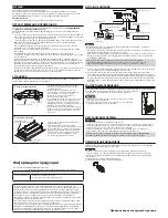
POWER SUPPLY
+ B
REM
GND
FUSE
30A
30A
POWER
4OMETALLICBODYORCHASSIS
4OANACCESSORYTERMINAL
Fuse*
#ARBATTERY
Ignition switch
JVC car receiver, etc.
Remote turn-on line
.OT3UPPLIED
Caution
4OPREVENTSHORTCIRCUITSWHILEMAKINGCONNECTIONSKEEPTHEBATTERYSNEGATIVETERMINAL
disconnected.
s7HENUSINGAPOWERCORDPURCHASEDSEPARATELY BESURETOPLACETHEFUSENEARTHEBATTERYAS
shown.
s#ONNECTTHELEADWIREPOWERCORD THROUGHWHICHPOWERISSUPPLIEDDIRECTLYTOTHEBATTERYS
“
ª
vTERMINALONLYAFTERALLTHEOTHERCONNECTIONSHAVEBEENMADE
The proper lead wire connected to each POWER terminal is as follows.
s"AND'.$!7'TO!7'4HECROSSSECTIONISABOUT
mm
2
to 21 mm
2
s2%-!7'TO!7'4HECROSSSECTIONISABOUT
mm
2
TO
mm
2
a
When you use JVC car receiver with a remote lead, connect to the REM terminal on this unit.
b
When you connect a unit without a remote lead, connect to the accessory circuit of the car
WHICHISACTIVATEDBYTHEIGNITIONSWITCH)NTHISCASENOISEMAYOCCURWHENTHECARRECEIVER
is turned on or off. To avoid this noise, do not turn on or off the car receiver itself. You can turn
on or off the car receiver along with the on/off operation of the ignition switch.
TERMINAL CONNECTIONS
7HENMAKINGTERMINALCONNECTIONSPROPERLYlXEACHTERMINALWITHTHEPROVIDEDSCREWBYTURNING
it as illustrated.
s5SERINGTERMINALSNOTPROVIDED FORSECURECONNECTION
Notes
s-AKESURETHESCREWISFIXEDINPLACETOPREVENTDISCONNECTIONS
s!VOIDOVERTIGHTENINGASITMAYCAUSETHEDAMAGETOTHESCREWORITS
head slot.
SPEAKER SYSTEMS
Notes
s"ESURENOTTOCONNECTTHEh
·
” terminals of the speakers to a common point.
s)FTHESAMELEADISUSEDFORBOTHLEFTRIGHTORFRONTREARSPEAKERWIRINGSTHISUNITCANNOTBEUSED
Always use the independent leads for each speaker. In this case, redo the wirings.
s5SETHESPEAKERSWITHANIMPEDANCEOF
Ω
TO
Ω
Ω
TO
Ω
WHENUSEDIN"RIDGE-ODE
s5SETHESPEAKERSWHICHHAVESUFFICIENTCAPACITYTOTHEUNIT
4HEPROPERLEADCONNECTEDTOEACH30%!+%2/54054TERMINALISASFOLLOWS
!7'TO!7'4HECROSSSECTIONISABOUTMM
2
to 3.3 mm
2
Dear JVC Customer in USA,
7ESUGGESTTHATYOUREGISTERYOURPRODUCTSINCEITWILLENABLEUSTOCONTACTYOUDIRECTLYIFITIS
ever necessary to correct a safety related condition in your product.
9OUCANREGISTERATWWWREGISTERJVCCOM
Please note that failure to register does not diminish any of your rights during the warranty
period.
SPEAKER CONNECTIONS
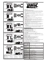
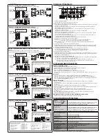
#ONNECTIONVARIESDEPENDINGONTHENUMBEROFTHESPEAKERSUSEDINYOURCAR3ELECTTHE
appropriate connection referring to the following diagrams.
Notes
s3ECURELYCONNECTALLTHEPARTS)FTHECONNECTIONSARELOOSEDUETOCONTACTRESISTANCEETCHEAT
WILLBREAKOUTANDMAYCAUSEANACCIDENT
s2UNTHECONNECTIONLEADSUNDERTHECARMATSTOPREVENTACCIDENTALDISCONNECTIONS
Å
When your receiver is equipped with line output.
ı
When your receiver is NOT equipped with line output.
For Customer Use
:
%NTERBELOWTHE-ODEL.OAND3ERIAL.OWHICH
ARELOCATEDONTHETOPORBOTTOMOFTHECABINET
Retain this information for future reference.
Model No.
3ERIAL.O
,64!
[K]
Continued to next page


