background image

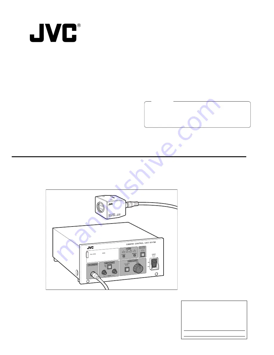
KY-F58

COLOR VIDEO CAMERA

INSTRUCTIONS

For Customer Use:

Enter below the Serial No. which 
are located on the bodys. 
Retain this information for future 
reference.

Model No. KY-F58

Serial No.

FREEZE

Digital

Memory

CAUTION

This section of instruction manual is specially edited for serv-
ice manual with modified contents.
It is not recommended to use this section for the substitution
of the original instructions included in the merchandise.

Summary of Contents for KY-F58

Page 1: ...tain this information for future reference Model No KY F58 Serial No FREEZE Digital Memory CAUTION This section of instruction manual is specially edited for serv ice manual with modified contents It is not recommended to use this section for the substitution of the original instructions included in the merchandise ...

Page 2: ...O PREVENT FIRE OR SHOCK HAZARD DO NOT EXPOSE THIS UNIT TO RAIN OR MOIS TURE Due to design modifications data given in this instruction book are subject to possible change without prior notice Changes or modifications not approved by JVC could void the user s authority to operate the equipment This unit is designed for professional use only WARNING TO PREVENT FIRE OR SHOCK HAZARD DO NOT EXPOSE THIS...

Page 3: ...N 23 TOTAL SETTING SCREEN 25 7 OTHERS TECHNICAL INFORMATION 26 SPECIFICATIONS 29 CONTENTS FEATURES High quality 1 3 and 3CCD format camera The camera head can be dismantled to produce a compact component A built in Frame Memory function enables a STROBE SYNC and RANDOM TRIGGER to operate the camera without add ing any further equipment Quick set up can be achieved with a Scene File Direct connecti...

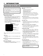
Page 4: ...o not leave the unit for long hours in a parked car under direct sunlight or near room heating equipment 䢇 Ambient Temperature Ambient temperature influence to an image sensing device Make sure to operate the camera in the temperature range of 5 C to 45 C 䢇 Ventilation holes A malfunction may be caused if heat is not properly venti lated Make sure that the cooling fan ventilation holes are not blo...

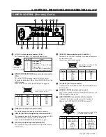
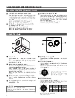
Page 5: ...20 21 and 22 to display the MENU screen When again pressing this button the normal screen is re sumed ON OFF CAMERA CONTROL UNIT KY F58 FREEZE FILES WHITE PAINT POWER VIDEO LEVEL TO CAMERA 4 3 2 1 MEMORY SELECT MENU FULL AUTO R B LEVEL PAINT SET PULL OPEN 1 13 14 15 3 4 16 19 17 18 5 2 LOCK SET ITEM ITEM DATA DATA RESET ON 4 3 2 1 ON OFF 7 10 11 12 6 8 9 BARS MENU 7 SET set button To choose the it...

Page 6: ...s button is pressed it becomes AUTOWHITE mode Refer to the WHITE BALANCE ADJUSTMENT on page 13 13 COVER To carry out the menu operation pull the cover towards you to open it 14 TO CAMERA camera connector Connect the camera head with the provided cable 5m 1 ON c 2 3 4 SW3 RANDOM TRIGGER setting Refer to Random Trigger Function on page 28 SW1 2 FILE setting Refer to FILE SETTING on page 15 SW4 Not a...

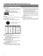
Page 7: ... 24 23 22 20 21 SIGNAL EARTH Pin No Detail Pin No Detail 1 2 3 4 5 NC RxD TxD DTR GND 6 7 8 9 DSR RTS CTS NC 1 6 5 9 View from the rear of the KY F58 9 pin connector male 20 Y C Y C output signal connector 4 Pin This connector outputs Y C separated video signal 21 RGB COMPONENT RGB Component output connector 9Pin This is the RGB Component signal output connector To switch between the RGB and the C...

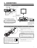
Page 8: ...t the lens to be used Refer to the MOUNTING THE OPTIONAL LENS T14 X 5 5MD TO THE CAMERA HEAD on page 9 View from the rear of the camera head 20 pin connector male For the signal names refer to the TO CAMERA on page 6 1 20 5 19 2 16 10 15 6 11 14 View from the rear of the camera head 8 pin connector female 7 1 6 8 4 2 3 5 Signal LENS SEL GND IRIS CTL IRIS Y 15V Pin No 1 2 3 4 Signal SERVO SEL ZOOM ...

Page 9: ...he screw of the camera head mount section to that of the lens mount section Turn the mount fastening ring slowly clockwise and fix the lens to the camera head by screwing it firmly To change the attitude angle of the lens rotating direction 1 Turn the mount fastening ring counter clockwise from the lens side 2 Turn the lens slowly to adjust the attitude angle and fas ten it again firmly with the m...

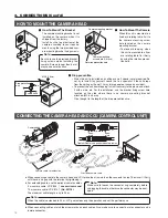
Page 10: ...Also make sure to connect a male connector and a female connector Rotation prevention hole Camera mounting bracket Camera mounting screw hole 1 4 inch 䡵 Drop prevention When this unit is installed on a ceiling or a wall special care is required Do not try to install it by yourself Leave this to a specialist If the unit drops from the ceiling or the wall it may injure people or cause an accident To...

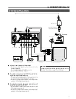
Page 11: ...EEZE connector Connect a flash light to the FLASH connector Set the FREEZE MENU to FLASH 䡵 To output an image from the KY F58 under the tim ing of the image processing unit Connect an external sync signal of the image processing unit to the VD and HD VBS connector of this unit Connect the image output connector to the image input connector of the image processing unit 䡵 To output an image to the i...

Page 12: ... volume of the monitor to adjust the color bar so that the brightness of 3 and 5 become the same 7 U Ver In case the brightness of 1 and 8 and 7 and 14 change when carrying out the PHASE adjustment start the proce dure again from step 4 E Ver In case the brightness of 1 and 7 change when carrying out the PHASE adjustment start the procedure again from step 4 8 Set the BLUE CHECK of the monitor to ...

Page 13: ... Error display ERROR OBJECT object in an unfavorable condition When there is not enough white color in the object or the color temperature is not suitable this error message is displayed Change the object into a white object and readjust the white balance ERROR LOW LIGHT shortage of light This message is displayed when the light is dark Turn the light up and readjust the white balance ERROR OVER L...

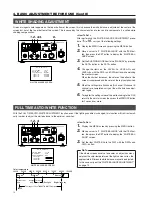
Page 14: ...hannels R channel G channel B channel are completed carry out the white balance adjust ment again 6 To register the setting values of the white shading to the FILE return to the normal screen then press the MEMORY button for 2 seconds or more WHITE BALANCE COLOR TEMP WHITE BAL SHADING MODE LEVEL R LEVEL G LEVEL B 3200K AUTO MANUAL NORMAL NORMAL NORMAL CAMERA CONTROL UNIT KY F58 FREEZE FILES WHITE ...

Page 15: ...TE PAINT POWER VIDEO LEVEL TO CAMERA 4 3 2 1 MEMORY SELECT FULL AUTO R B LEVEL ON OFF PAINT SET LOCK MENU SET ITEM ITEM DATA DATA RESET BARS ON 4 3 2 1 ON OFF Changing setting values MEMORY button 䡵 Changing setting values The setting value is changed for each file Refer to the 6 SETTINGS ON THE MENU SCREEN on page 18 䡵 Registration to the FILE Setting values can be registered to each FILE Press t...

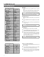
Page 16: ... The reset is completed when the LED stops blinking and lights Note The TOTAL SETTING screen will not be initialized FILE SETTING Cont d Item Initial Values of Scene File A Initial Values LENS TYPE IRIS CONTOROL SHUTTER AUTO AUTO NORMAL 0 dB 18 dB NORMAL NORMAL 3200K AUTO OFF NORMAL ALTERNATE OFF FRAME NORMAL NORMAL OFF OFF 100 110 ON NORMAL NORMAL ADJUST NORMAL LEVEL GAIN LEVEL ALC MAX IRIS DETEC...

Page 17: ...EL The video signal level at each OUTPUT can be varied with the LEVEL adjust knob With regard to the amount of the video level variability available at the FULL AUTO button by using the LEVEL adjust knob refer to the chart on the left 䢇 Convergence Level Adjustment The convergence level which is a standard value for the Auto Iris can be finely adjusted Turning the LEVEL adjust knob to the right op...

Page 18: ...AME Memory environment setting screen ITEM button TOTAL SETTINGS D SUB OUT ON SYNC LENS CONTROL INDICATOR SC CORASE SC FINE H PHASE R G B OFF CONTROLLER OFF CABLE LENGTH 5M 0 0 0 Total setting menu screen WHITE BALANCE COLOR TEMP WHITE BAL SHADING MODE LEVEL R LEVEL G LEVEL B 3200K AUTO OFF White balance setting menu screen PROCESS 1 2 DETAIL MASTER BLACK NEGA AUTO KNEE KNEE POINT WHITE CLIP NORMA...

Page 19: ...TEP Increase sensitivity Press the DATA button Decrease sensitivity Press the DATA button V GAIN 0 2dB 18 0dB 0 2 dB step STEP 6dB 9dB 12dB 18dB ALC MAX Max GAIN for the ALC which changes the sensitivity automatically according to brightness 6 dB Max GAIN is 6 dB 12 dB Max GAIN is 12 dB 18 dB Max GAIN is 18 dB 6dB 12dB 18dB IRIS DETECT The setting value of the detection level in the AUTO IRIS mode...

Page 20: ...s the sun etc WHITE BALANCE Different modes for the white balance can be set MANUAL PRESET AUTO FAW White balance can be varied manually with the PAINT R adjust knob or the PAINT B adjust knob White balance is fixed to the setting value 3200 K or 5200 K of the COLOR TEMP item It is set to carry out the white balance adjustment Refer to the WHITE BALANCE ADJUSTMENT on page 13 The white balance trail...

Page 21: ...TRG FLASH SLOW SHUT Functions and operation Variable values NORMAL RANDOM TRG FLASH SLOW SHUT KY F58 stores the video signal into its memory and outputs the FREEZE signal freeze picture from each OUTPUT connector on the rear panel It sets the timing of freeze or whether it is operated together with a flash light or not The image is stored in the KY F58 s memory when the FREEZE button is pressed or...

Page 22: ...values are changed by pressing the DATA button it takes a longer time to display the setting values and the blinking time of the setting value When the shutter speed is decreased it takes a longer time to record the image into the memory so that white doted scratches also increase The image in the odd number fields are output to the both fields The image in the even number fields are output to the...

Page 23: ...level video signal To increase the white clip point Increase the numbers To decrease the white clip point Decrease the numbers 110 105 100 Functions and operation Variable values NEGA This outputs the reversed video signal of the output terminal OFF Reverse is not carried out ON Reverse is carried out This adjusts the pedestal level master black which is the standard black level when a lens cap is...

Page 24: ... operation Variable values ABL It sets the black level auto adjustment of video signal during recording Adjust this when the black level varies when shooting images OFF ABL adjustment cannot be carried out ADJUST ABL adjustment can be carried out OFF ADJUST This sets the ABL adjustment level It is available only when the ABL is set to the ADJUST To increase black level Increase the numbers To decr...

Page 25: ...RIS on each output connector OFF No display ON Display This selects the signals output from the RGB COMPONENT output connector on the rear panel of the KY F58 RGB RGB signal is output COMPONENT Y R Y B Y signals are output It sets the SYNC signal to add to the RGB signals output from the RGB COMPONENT output connector on the rear panel of the KY F58 Only available when the D SUB OUT is set to RGB ...

Page 26: ... U Ver or 1 25 sec E Ver with the High Resolution mode which is twice that of the Normal mode However there is approx 1 60 sec U Ver or 1 50 sec E Ver one field difference in the output timings between odd number line and even number line With the odd number fields electric charge of the odd number line is only output to the odd number line and with the even fields the electric charge of even line...

Page 27: ...Ver or 1 50 E Ver to 1 1920 U Ver or 1 1600 E Ver sec The signal level is adjusted in the range of 3 dark to 5 bright When the iris is set to the manual mode the sensitivity and the electronic shutter vary continuously without varying the iris setting This function enables recording an object without varying its depth under variable illuminance With a lens Illuminance lx 8 16 32 62 5 125 250 500 1...

Page 28: ... the SW3 of set up switch Before switching the set up switch turn the power switch to off The mode will not change when the power is switched ON Note SYNC Non Reset mode SYNC Reset mode MODE SWITCH SETTING 3 ON 3 OFF 1 2 4 Do not switch over 1 2 4 Do not switch over 1 2 3 4 1 2 3 4 NO NO Trigger signal Electric charge to be stored in CCD Camera video output signal WEN signal Camera video output si...

Page 29: ...HD VD 4 Vp p 75 Ω negative electric signal without color lock EXT TRIGGER FLASH output Open connector negative electric signal WEN output 5 Vp p negative electric signal FREEZE input 5 Vp p negative electric signal Contour compensation system H Both effective V One effective Standard cable length 5 m Max cable length 25 m operation only guaranteed Registration 0 05 except lens Sensitivity F5 6 200...

Page 30: ...209 5 1 6 92 5 12 3 221 245 4 73 5 CAMERA CONTROL UNIT KY F58 FREEZE FILES WHITE PAINT POWER VIDEO LEVEL TO CAMERA 4 3 2 1 MEMORY SELECT MENU RGB COMPONENT Y C VIDEO HD VBS FREEZE VD WEN FLASH OUTPUT EXT REF EXT TRIGGER RS 232C FULL AUTO R B LENS REMOTE SEE INSTRUCTION MANUAL AC INPUT LEVEL ON OFF PAINT SET PULL OPEN Design and specifications are subject to change without notice Dimensions unit mm...

Reviews: