background image

SERVICE MANUAL

COPYRIGHT © 2005 Victor Company of Japan, Limited

No.YA344

2005/10

WIDE LCD PANEL TELEVISION

YA344

2005

10

LT-26AX5, LT-26AX5

/S

LT-32AX5, LT-32AX5

/S

TABLE OF CONTENTS

1

PRECAUTION. . . . . . . . . . . . . . . . . . . . . . . . . . . . . . . . . . . . . . . . . . . . . . . . . . . . . . . . . . . . . . . . . . . . . . . . .  1-3

2

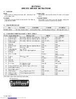
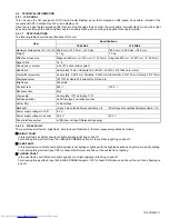
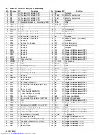
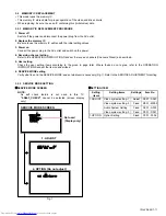
SPECIFIC SERVICE INSTRUCTIONS . . . . . . . . . . . . . . . . . . . . . . . . . . . . . . . . . . . . . . . . . . . . . . . . . . . . . .  1-6

3

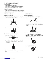
DISASSEMBLY  . . . . . . . . . . . . . . . . . . . . . . . . . . . . . . . . . . . . . . . . . . . . . . . . . . . . . . . . . . . . . . . . . . . . . . .  1-9

4

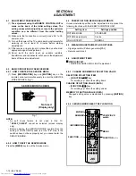
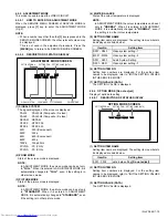
ADJUSTMENT . . . . . . . . . . . . . . . . . . . . . . . . . . . . . . . . . . . . . . . . . . . . . . . . . . . . . . . . . . . . . . . . . . . . . . .  1-14

5

TROUBLESHOOTING . . . . . . . . . . . . . . . . . . . . . . . . . . . . . . . . . . . . . . . . . . . . . . . . . . . . . . . . . . . . . . . . .  1-18

BASIC CHASSIS

FT

Summary of Contents for LT-26AX5

Page 1: ...n Limited No YA344 2005 10 WIDE LCD PANEL TELEVISION YA344 2005 10 LT 26AX5 LT 26AX5 S LT 32AX5 LT 32AX5 S TABLE OF CONTENTS 1 PRECAUTION 1 3 2 SPECIFIC SERVICE INSTRUCTIONS 1 6 3 DISASSEMBLY 1 9 4 ADJUSTMENT 1 14 5 TROUBLESHOOTING 1 18 BASIC CHASSIS FT ...

Page 2: ...625MHz 4 25MHz 3 58MHz 4 43MHz LCD panel 26V inch wide aspect 16 9 32V inch wide aspect 16 9 Screen Size Diagonal 65 cm H 57 6 cm V 32 4 cm Diagonal 80 cm H 69 7 cm V 39 2 cm Display Pixels Horizontal 1366 dots Vertical 768 dots W XGA Audio Power Output 5 W 5 W Speaker 6 6 cm round type 2 Oblique corn Aerial terminal VHF UHF 75 Ω unbalanced coaxial VIDEO 1 VIDEO 2 Input Output 21 pin Euro connecto...

Page 3: ...ts that indicate evidence of overheating should be replaced Always use the manufacturer s replacement components 6 Isolation Check Safety for Electrical Shock Hazard After re assembling the product always perform an isolation check on the exposed metal parts of the cabinet antenna terminals video audio input and output terminals Control knobs metal cabinet screw heads earphone jack control shafts ...

Page 4: ...ing in order to protect against accidents and earthquakes 1 2 3 INSTALLATION REQUIREMENTS To ensure safety in an emergency such as an earthquake and to prevent accidents ensure that measures are taken to prevent the TV dropping or falling over 1 2 4 NOTES ON HANDLING 1 WHEN TAKING UNIT OUT OF A PACKING CASE When taking the unit out of a packing case do not grasp the upper part of the unit If you t...

Page 5: ...uring transportation and storage as the LCD panel is very vulnerable to lateral impacts and may break During transportation ensure that the unit is loaded along the traveling direction of the vehicle and avoid stacking them on one another For storage ensure that they are stacked in 2 layers or less even when placed upright 1 3 2 OPTICAL FILTER ON THE FRONT OF THE LCD PANEL 1 Avoid placing the unit...

Page 6: ...ut 500mV rms Nominal Low impedance Used TV OUT Used LINE OUT 2 AUDIO R input 500mV rms Nominal High impedance Used R1 Used R2 3 AUDIO L output 500mV rms Nominal Low impedance Used TV OUT Used LINE OUT 4 AUDIO GND Used Used 5 GND B Used Used 6 AUDIO L input 500mV rms Nominal High impedance Used L1 Used L2 7 B input 700mV B W 75Ω Used Used 8 FUNCTION SW SLOW SW Low 0V 3V High 8V 12V High impedance U...

Page 7: ...0 of each R G B colour and find out the cell that is not lighting FLICKER FAULT In the pixel fault a cell that should light originally or not light originally is flashing on and off For checking this pixel fault input ALL BLACK SCREEN signal or 100 of each RGB colour and find out the cell that is flashing on and off Item Specifications LT 26AX5 LT 32AX5 Maximum dimensions W H D 626 0 mm 373 0 mm 5...

Page 8: ...26 P2 2 I key scan data 2 76 A14 O Program ROM address for CPU 27 P2 3 I Scaet1 ID H Detect 77 A12 O Program ROM address for CPU 28 NC1 Not used 78 A13 O Program ROM address for CPU 29 HS SSC I Horizontal sync 79 A7 O Program ROM address for CPU 30 VS I Vertical sync 80 FL_RST Test purpose 31 P3 0 O Data Read for Scaler IC 81 A8 O Program ROM address for CPU 32 P3 1 O Comunication for adjustment H...

Page 9: ...ve the STAND Remove the REAR COVER Remove the TERMINAL BASE Remove the BACK BRACKET Remove the POWER PWB SHIELD 1 Remove the 7 screws L and 2 screws N then remove the MAIN PWB SHIELD 2 Remove the 6 screws M then remove the MAIN PWB 3 1 5 REMOVING THE KEY PWB Remove the STAND Remove the REAR COVER 1 Remove the 2 screws P then remove the KEY PWB 3 1 6 REMOVING THE LED PWB Remove the STAND Remove the...

Page 10: ... POWER CORD LCD PANEL UNIT CONTROL PWB KNOB BASE LED PWB FRONT PANEL TERMINAL BASE SPEAKER STAND STAND COVER SPEAKER MAIN PWB C D F A B F L M G H R S R N P V T U U T K S J E Q CONTROL KNOB This exploded view shows the LT 26AX5 LT 32AX5 slightly differs from this exploded view however it can be disassembled in the same procedure as LT 26AX5 ...

Page 11: ...not agree refer to the OPERATING INSTRUCTIONS and set the items as described 6 SERVICE MODE setting Verify what to set in the SERVICE MODE and set whatever is necessary Fig 1 Refer to the SERVICE ADJUSTMENT for setting 3 2 2 SERVICE MODE SETTING SERVICE MODE SCREEN NOTE As self check feature is not used in this TV 2 SELF_CHECK cannot be selected screen display only Fig 1 SETTING ITEM SERVICE MENU ...

Page 12: ...ND OFF Setting item Setting position PICTURE MODE BRIGHT WHITE BALANCE COOL FEATURES DIGITAL VNR AUTO LOW COLOUR SYSTEM TV Depends on PR CH EXT AUTO Setting item Setting position STEREO I II Stereo sound BASS Centre TREBLE Centre BALANCE Centre 3D SOUND OFF Setting item Setting position SLEEP TIMER OFF CHANNEL GUARD APPEARANCE TYPE D BLUE BACK ON FAVOURITE SETTING Reset Setting item Setting positi...

Page 13: ...the tweezers and remove the chip part Transistors diodes variable resistors etc 1 Apply extra solder to each lead 2 As shown in the figure push the part with tweezers and alternately melt the solder at each lead Shift and remove the chip part NOTE After removing the part remove remaining solder from the pattern 2 How to install Chip parts Resistors capacitors etc 1 Apply solder to the pattern as i...

Page 14: ... adjustment 4 5 BASIC OPERATION OF SERVICE MODE 4 5 1 HOW TO ENTER THE SERVICE MODE 1 Press INFORMATION key and MUTING key on the remote control unit simultaneously to enter the SERVICE MODE SCREEN Fig 1 Fig 1 NOTE As self check feature is not used in this TV 2 SELF_CHECK cannot be selected screen display only Before entering the SERVICE MODE confirm that the setting of VCR TV DVD switch is at the...

Page 15: ...s in other colour temperature 5 SETTING ITEM NAME Setting item name are displayed The setting item numbers to be displayed are listed below 6 SETTING ITEM NO Setting item numbers are displayed For the setting item names to be displayed refer to INITIAL SETTING VALUES IN THE SERVICE MODE 7 SETTING VALUE DATA The SETTING VALUE is displayed 4 5 6 OPTION MODE Do not adjust Display of optin data settin...

Page 16: ...28 HD WM R DR 32 31 00 S029 HD WM G DR 32 31 00 S030 HD WM B DR 32 31 00 S031 PC R OF 000 255 133 S032 PC G OF 000 255 121 S033 PC B OF 000 255 115 S034 PC R DR 32 31 15 S035 PC G DR 32 31 14 S036 PC B DR 32 31 10 S037 PC CL R DR 32 31 00 S038 PC CL G DR 32 31 00 S039 PC CL B DR 32 31 00 S040 PC WM R DR 32 31 00 S041 PC WM G DR 32 31 00 S042 PC WM B DR 32 31 00 S043 PC AUTO WB 000 001 000 Item No ...

Page 17: ...1 016 D039 SFT BRI1 000 031 014 D040 SFT CON 000 031 014 D041 SFT BRI2 000 031 014 D042 SFT SHA 000 031 014 D043 SFT COL 000 031 014 D044 SFT TIN 000 031 016 D045 BRI BRI1 000 031 031 D046 BRI CON 000 031 018 D047 BRI BRI2 000 031 016 D048 BRI SHA 000 031 018 D049 BRI COL 000 031 016 D050 BRI TIN 000 031 016 D051 PWM 000 031 008 Item No Item name Variable range Setting value Item No Item name Vari...

Page 18: ...l 2 Set PICTURE MODE to STANDARD 3 Set ZOOM to FULL 4 Set WHITE BALANCE to NORMAL 5 Select 1 ADJUST from the SERVICE MODE 6 Set S013 R DRIVE S015 G DRIVE and S017 B DRIVE to 145 7 Adjust to Keep one of S030 Red drive S031 Green drive or S032 Blue drive unchanged then lower the other two so that the all white screen is equally white throughout NOTE Set one or more of S013 S015 and S017 to 145 8 Che...

Page 19: ... No YA344 AV MULTIMEDIA COMPANY DISPLAY CATEGORY 12 3 chome Moriya cho Kanagawa ku Yokohama city Kanagawa prefecture 221 8528 Japan Victor Company of Japan Limited VPT Printed in Japan ...

Page 20: ...COPYRIGHT 2005 Victor Company of Japan Limited No YA344 2005 10 WIDE LCD PANEL TELEVISION YA344 2005 10 LT 26AX5 LT 26AX5 S LT 32AX5 LT 32AX5 S BASIC CHASSIS FT SCHEMATIC DIAGRAMS CD ROM No SML200510 ...

Page 21: ...ply Type MM Metalized mylar capacitor PP Polypropylene capacitor MPP Metalized polypropylene capacitor MF Metalized film capacitor TF Thin film capacitor BP Bipolar electrolytic capacitor TAN Tantalum capacitor 3 Coils No unit Others µH As specified No indication Ceramic capacitor 2 Capacitors Capacitance value 1 or higher pF less than 1 µF Withstand voltage No indication DC50 V Others DC withstan...

Page 22: ...AMS MAIN PWB PATTERN 2 31 POWER PWB PATTERN 2 35 KEY PWB PATTERN 2 37 LED PWB PATTERN 2 37 VOLTAGE CHATRS 2 38 WAVEFORMS 2 39 USING P W BOARD IC BOTTOM VIEW FRONT VIEW TOP VIEW 1 N N 1 OUT E IN IN OUT E 1 N TOP VIEW 1 N 1 N CHIP IC TRANSISTOR BOTTOM VIEW FRONT VIEW TOP VIEW CHIP TR E C B E C B C B E B G E S C D E C B E C B P W B ASS Y name MAIN P W BOARD POWER P W BOARD LED P W BOARD KEY P W BOARD...

Page 23: ...EL UNIT POWER CORD WIRING DIAGRAM CN2 CN1 CN3 LCD PANEL UNIT LCD PANEL UNIT POWER PWB J602 J501 J304 J210 J209 J801 J601 MAIN PWB SPEAKER R SPEAKER L H701 U V TUNER J210 1 4 1 LED PWB TOP TOP J209 1 7 1 CONTROL PWB 10 1 15 4 7 1 1 30 1 1 2 1 3 4 1 1 15 1 ...

Page 24: ...T 2 J204 J205 EXT 3 S VIDEO VIDEO AUDIO L R J205 EXT 4 Y Pb Pr DACM_R L OUT2 OUT1 HEAD PHONE L R IR SCL SDA KEY 0 1 DACA_L R OSD R G B FB POWER PWB SPEAKER SOUND PROCESS SOUND SELECT D A HEADPHONE SOUND PROCESS D A SCART OUTPUT SELECT D A A D A D AGC DEMOD H701 U V TUNER U603 HEADPHONE AMP U301 PROGRAM DATA 4Mbit U303 MAIN MEMORY SETTING DATA U101 VIDEO INPUT SELECT U602 MULTI SOUND PROCESS U301 M...

Page 25: ... R504 4 7K R809 0 R376 270 ZD228 KDZ5 6V CE404 10uF 16V R347 100 C227 473 TP602 R417 22 C417 104 RN513 B 300A R440 OPEN R510 B 300 ZD263 KDZ5 6V RA05 33 C216 471 R374 22K C434 104 R109 100K C635 105 R351 33 R592 B 300 R240 75 R586 B 300 L505 B 501 3216 CE305 10uF 16V CE203 10uF 16V C221 471 C249 334 C307 103 D602 KDS181 2 3 1 CE502 220uF 16V 105 C109 106 2012 CE102 47uF 16V 105 L610 B 800 3216 R24...

Page 26: ... ZD256 KDZ5 6V C535 104 RN310 4 7KA R332 22 Q502 GM66102 2 5TC3 TO 252 IN 1 G 2 OUT 3 L408 B 501 3216 C405 104 C444 104 R574 100 C407 104 R443 OPEN L404 B 501 3216 RA06 33 RA08 33 R313 100 TP302 R415 680 C310 104 CE510 22uF 16V C552 104 RN410 B 300A R416 22 RN516 B 300A C5 10 R387 OPEN C516 104 C418 OPEN R325 OPEN C415 104 R432 33 C422 152 C447 104 C506 104 CE301 100uF 10V 105 R346 100 R349 4 7K R...

Page 27: ...2 NC6 191 NC7 190 NC8 189 NC9 188 LVB0M 187 LVB0P 186 LVB1M 181 LVB1P 180 LVB2M 179 LVB2P 178 LVBCKM 177 LVBCKP 176 LVB3M 175 LVB3P 174 LVA0M 171 LVA0P 170 LVA1M 169 LVA1P 168 LVA2M 167 LVA2P 166 LVACKM 165 LVACKP 164 LVA3M 161 LVA3P 160 DQS 0 153 MDATA 0 152 MDATA 1 151 MDATA 2 150 MDATA 3 149 MDATA 4 148 MDATA 5 147 MDATA 6 146 MDATA 7 145 MDATA 8 144 MDATA 9 143 MDATA 10 142 MDATA 11 141 MDATA ...

Page 28: ...0 100 L802 B 800 3216 R801 10K R220 1K J101 CON2P S02B PH 2 1 2 R370 10K R504 4 7K R809 0 R376 270 C216 471 R374 22K R109 100K CE305 10uF 16V CE203 10uF 16V C221 471 C109 106 2012 CE102 47uF 16V 105 D209 KDZ5 6V C222 471 Q202 KTC3875S Y 2 3 1 C215 10P R806 4 7K Q108 KTC3875S Y 2 3 1 Q105 KTC3875S Y 2 3 1 CE804 100uF 16V R284 OPEN J304 CON4P A2008WV0 4P 1 2 3 4 C217 471 Q317 KRC111S 2 3 1 CE802 470...

Page 29: ...72 100 C210 102 C232 471 C233 471 Q204 KTC3875S Y 2 3 1 C235 471 L703 680uH CE201 47uF 16V R256 75 C632 331 IR201 KSM 913TC5N G VC IR C703 103 CE623 1uF 50V C246 332 C238 10P R298 10K R708 100 L705 470uH U603 TDA7050T A 1 B 2 C 3 D 4 GND 5 E 6 F 7 VCC 8 L210 B 800 CE621 10uF 16V C203 473 C623 392 L240 B 501 3216 R209 680 C236 10P L213 B 800 ZD208 KDZ5 6V R206 680 ZD202 KDZ5 6V LD201 LED ZD262 KDZ5...

Page 30: ...VC IR C246 332 R298 10K R209 680 L240 B 501 3216 LD201 LED R206 680 S203 R K097110R C247 332 J210 1 CON4P A2004WR0 4P 1 2 3 4 EAR PHONE R L J207 PPJ 35G 01 8 5 6 10 9 4 7 8 5 6 10 9 4 7 R201 4 7K J209 1 CON7P A2004WV0 7P 1 2 3 4 5 6 7 L226 B 800 R202 1K R207 2 2K ZD229 KDZ5 6V R293 33 Q201 KTC3875S Y 2 3 1 R250 0 R203 10 R297 10K KEY PWB ASS Y QAL0795 001 LED PWB ASS Y QAL0794 001 MAIN PWB ASS Y 1...

Page 31: ...2 20 No YA344 No YA344 2 19 POWER PWB ASS Y 1 3 QAL0793 001 POWER CORD POWER PWB CIRCUIT DIAGRAM 1 3 SHEET 7 LT 26AX5 LT 26AX5 S ...

Page 32: ... No YA344 2 21 2 22 No YA344 POWER PWB ASS Y 2 3 QAL0793 001 POWER PWB CIRCUIT DIAGRAM 2 3 SHEET 8 LT 26AX5 LT 26AX5 S ...

Page 33: ...2 24 No YA344 No YA344 2 23 MAIN PWB ASS Y 3 4 J801 SHEET3 LCD PANEL UNIT POWER PWB ASS Y 3 3 QAL0793 001 POWER PWB CIRCUIT DIAGRAM 3 3 SHEET 9 LT 26AX5 LT 26AX5 S ...

Page 34: ... No YA344 2 25 2 26 No YA344 POWER CORD POWER PWB ASS Y 1 3 QAL0793 001 POWER PWB CIRCUIT DIAGRAM 1 3 SHEET 10 LT 32AX5 LT 32AX5 S ...

Page 35: ... No YA344 2 27 2 28 No YA344 POWER PWB ASS Y 2 3 QAL0793 001 POWER PWB CIRCUIT DIAGRAM 2 3 SHEET 11 LT 32AX5 LT 32AX5 S ...

Page 36: ... No YA344 2 29 2 30 No YA344 MAIN PWB ASS Y 3 4 J801 SHEET3 LCD PANEL UNIT POWER PWB ASS Y 3 3 QAL0793 001 POWER PWB CIRCUIT DIAGRAM 3 3 SHEET 12 LT 32AX5 LT 32AX5 S ...

Page 37: ... No YA344 2 31 2 32 No YA344 TOP PATTERN DIAGRAMS MAIN PWB PATTERN SOLDER SIDE ...

Page 38: ...2 34 No YA344 No YA344 2 33 TOP MAIN PWB PATTERN PARTS SIDE ...

Page 39: ... No YA344 2 35 2 36 No YA344 TOP TOP POWER PWB PATTERN SOLDER SIDE POWER PWB PATTERN PARTS SIDE ...

Page 40: ...91 0 3 92 0 6 93 0 4 94 0 4 95 0 3 96 0 4 97 0 3 98 0 4 99 0 3 100 0 101 0 102 2 5 103 0 104 1 8 105 2 5 106 1 4 107 1 3 108 0 109 3 2 110 1 2 111 1 4 112 0 113 2 5 114 0 115 2 0 116 2 4 117 0 2 118 1 0 119 0 2 120 1 0 121 1 1 122 1 0 123 1 0 124 1 4 125 2 5 126 0 127 0 128 0 129 0 130 0 131 1 7 132 0 133 0 134 0 135 0 2 136 0 2 137 0 3 138 0 7 139 2 4 140 0 141 0 4 142 0 2 143 0 3 144 0 2 145 0 3...

Page 41: ... 15 3 0 Vp p 0 2µs U402 16 4 1 Vp p 0 2µs U402 19 3 2 Vp p H 3 2 Vp p V U402 20 U402 61 1 0 Vp p H MAIN PWB 2 4 SHEET2 U501 53 4 2 Vp p 0 5µs 3 2 Vp p H U501 51 U501 77 3 2 Vp p V U501 202 4 9 Vp p 0 5µs U501 203 4 0 Vp p 0 5µs U602 71 2 6 Vp p 0 5µs U602 72 3 4 Vp p 0 5µs U101 41 3 1 Vp p U101 44 3 1 Vp p H MAIN PWB 3 4 SHEET3 H U101 53 2 2 Vp p H U101 63 1 4 Vp p H WAVEFORMS ...

Page 42: ...2 40 No YA344 ...

Page 43: ... No YA344 AV MULTIMEDIA COMPANY DISPLAY CATEGORY 12 3 chome Moriya cho Kanagawa ku Yokohama city Kanagawa prefecture 221 8528 Japan Victor Company of Japan Limited VPT Printed in Japan ...

Page 44: ...WIDE LCD PANEL TV INSTRUCTIONS LT 32AX5 LT 26AX5 ENGLISH LCT1926 001A H ...

Page 45: ......

Page 46: ...NOT EXPOSE THIS APPLIANCE TO RAIN OR MOISTURE WARNING Fingers may be trapped under the TV causing injuries Hold the TV at the bottom in the middle and do not allow it to tilt up or down WARNING The TV may fall causing injuries Hold the bottom of the stand with your hand and tilt the TV up and down Do not allow children to hang from the TV place their elbows on the TV or lean against the TV Doing s...

Page 47: ... installation and never position the unit where good ventilation is impossible When installing this TV distance recommendations must be maintained between the set and the wall as well as inside a tightly enclosed area or piece of furniture Keep to the minimum distance guidelines shown for safe operation Pixel defects LCDs use collections of fine points pixels to display images While there is no pr...

Page 48: ...rn to TV channel instantly 16 Favourite channel function 17 Operating a JVC brand VCR or DVD player 18 Teletext function 19 Basic operation 19 Using the List Mode 19 Hold 20 Sub page 20 Reveal 20 Size 20 Index 21 Cancel 21 Using the TV s menu 22 Basic operation 22 PICTURE menu 23 PICTURE MODE 23 BACK LIGHT 23 CONTRAST 23 BRIGHT 23 SHARP 23 COLOUR 23 TINT 23 WHITE BALANCE 23 FEATURES 24 SOUND menu ...

Page 49: ...ect the equipment to the TV making the correct rear panel and front panel connections Before connecting anything Read the manuals that came with the equipment Depending on the equipment the connection method may be different from the diagram Also the equipment settings may need to change depending on the connection method Turn off all the equipment including the TV The Specifications on page 38 gi...

Page 50: ...ing cables are not provided If you are not connecting a VCR DVD recorder If you are connecting a VCR DVD follow A B in the diagram below Aerial 75 ohm Coaxial Cable 75 ohm Coaxial Cable 75 ohm Coaxial Cable To Aerial Output To Aerial Input VCR DVD recorder Aerial ...

Page 51: ...utput Teletext programmes cannot be output Connecting to the VIDEO 3 terminal S VIDEO or video input To play the VCR DVD player Connect the TV to the VIDEO 3 terminal of the VCR DVD player You can choose between an S VIDEO signal Y C signal and a normal video signal composite signal For details of how to operate the equipment see VIDEO 3 SETTING on page 33 You can also connect game consoles and ca...

Page 52: ...cting the PC For details see Connecting to the computer on page 34 Cable holder A cable holder which is used to keep the connection cables tidy is attached to the back of the stand Gently squeeze the left and right of the cable holder and pull it to remove it from the stand After putting the cables in the cable holder attach it to the back of the stand again DVD player To OUTPUT COMPONENT IN AUDIO...

Page 53: ... setting up and testing your TV please replace them as soon as you need to Initial settings When the TV is first turned on it goes into the initial settings mode and you will see the JVC logo Follow the instructions on the screen display to make the initial settings 1 Make sure to set the VCR TV DVD switch on the remote control to the TV position You cannot turn the TV on when the VCR TV DVD switc...

Page 54: ... the programme numbers PR list To stop the AUTO PROGRAM function press the b button 6 After the TV channels have been registered in the programme numbers PR the EDIT menu appears You can proceed to edit the programme numbers PR list using the EDIT MANUAL function For details see EDIT MANUAL on page 29 If a TV channel you want to view is not stored in the programme numbers PR list you can register ...

Page 55: ...om standby mode When the TV is turned on the power lamp lights blue To turn the TV off Press the A button again The power lamp goes off Caution The A button on the TV does not fully isolate the TV from the AC supply If you are not going to use the TV for a long period be sure to disconnect the AC plug from the AC socket Choose a TV channel Press the P p buttons to choose a programme number PR Watc...

Page 56: ...etails of using the menu Connecting headphones Connect the headphones with a stereo mini jack 3 5 mm diameter to the headphone jack at the TV front panel No sound comes from the TV speakers when the headphones are connected Using the stand This stand can be used to adjust the direction of the TV screen 5 up 10 down and 20 to the left or right Tilt the TV up and down Rotate the TV to the left and r...

Page 57: ...b button r Volume q buttons Turn the TV on or off from standby mode Press the standby button to turn the TV on or off When the TV is turned on the power lamp lights blue The power can be turned on by pressing the b button p p buttons or Number buttons 0 3 4 5 9 6 7 8 1 2 To turn the TV on or off set the VCR TV DVD switch on the remote control to the TV position and press the button If the VCR TV D...

Page 58: ...inal video source the motion may appear unnatural when the video source is input with progressive scanning component signals If this happens change the output setting of the connected device to interlace scanning component signal output See the instructions that came with the device for more information The PC sound is the same as the VIDEO 3 sound To return to a TV channel Press the b button the ...

Page 59: ... the display as follows Channel number display The channel number and channel name when the channel name is registered of the programme you are watching or the VIDEO terminal number is displayed PR LIST The programme number PR and VIDEO terminal list is displayed Pressing the a button after choosing the programme number PR or VIDEO terminal with the 7 buttons will display the chosen programme or V...

Page 60: ...t ratio to the upper and lower limits of the screen 16 9 ZOOM This zooms up the wide picture 16 9 aspect ratio to the full screen 16 9 ZOOM SUBTITLE This zooms up the wide picture 16 9 aspect ratio with subtitles to the full screen FULL This uniformly stretches the left and right sides of a normal picture 4 3 aspect ratio to fill the wide TV screen For 16 9 aspect ratio pictures that have been squ...

Page 61: ...e performed The power is turned off on g Text button is pressed The TV is switched between TV mode and VIDEO mode 3D SOUND function You can enjoy sounds with a wider ambience This function does not work for the sound from headphones Press the 3 button to select one of 3D SOUND modes ON When you listen to stereo sound please select ON mode You can enjoy sound similar to the experience at the theatr...

Page 62: ... 4 NOT AVAILABLE appears on the screen Channels locked with the CHANNEL GUARD function cannot be registered If AUTO PROGRAM is performed the registered favourite channels are reset When you want to delete a favourite channel delete the set channel and set contents with FAVOURITE SETTING see page 28 in the FEATURES menu Calling the favourite channel 1 In the normal screen press the d favourite butt...

Page 63: ...an also press the H or T button and display the DVD disc menu screen and then operate by pressing the 7 buttons 2 Press the VCR DVD Control Button to control your VCR or DVD player If your device is not made by JVC these buttons will not work Even if your device is made by JVC some of these buttons may not work depending on the device you are using You can use the p buttons to choose a TV channel ...

Page 64: ...sult your local dealer or the teletext station The ZOOM function will not work in the TV and text mode or Text mode You cannot operate menus when viewing a teletext programme If characters on a teletext programme do not appear properly change the TELETEXT LANGUAGE setting For details see TELETEXT LANGUAGE on page 33 Using the List Mode You can store the numbers of your favourite teletext pages in ...

Page 65: ... are being received Press the C Hold button To cancel the Hold function Press C Hold button again Sub page Some teletext pages include sub pages that are automatically displayed You can hold any sub page or view it at any time 1 Press the d Favourite button to operate the Sub page function 2 Press the Number buttons to enter a sub page number Example 3rd sub page press 0 0 0 and 3 To cancel the Su...

Page 66: ...mber button to enter a page number or press a colour button The TV searches for a teletext page 2 Press H Cancel button The TV programme appears When the TV finds the teletext page its page number appears in the upper left of the screen 3 Press H Cancel button to return to a teletext page when the page number is on the screen The TV mode cannot be resumed by pressing the H Cancel button To return ...

Page 67: ...or H button to exit from the menu Some menu items may not be operated or set depending on the TV status or other menu item settings Menu items that cannot be operated or set are displayed in grey in the menu and cannot be chosen Types of menu The menu will disappear after about one minute if no operation is performed Operation with the buttons on the TV You can also operate the menus using the but...

Page 68: ...djustment SOFT Softens contrast and sharpness BACK LIGHT You can adjust the back light 2 darker 3 brighter CONTRAST You can adjust the picture contrast 2 lower 3 higher BRIGHT You can adjust the picture brightness 2 darker 3 brighter SHARP You can adjust the picture sharpness 2 softer 3 sharper COLOUR You can adjust the picture colour 2 lighter 3 deeper TINT You can adjust the picture tint 2 reddi...

Page 69: ...M The colour system is chosen automatically However if the picture is not clear or no colour appears choose the colour system manually 1 Choose COLOUR SYSTEM Then press the a or 3 button The sub menu of the COLOUR SYSTEM function appears 2 Press the 6 buttons to choose the appropriate colour system Then press the a button PAL PAL system SECAM SECAM system NTSC 3 58 NTSC 3 58 MHz system NTSC 4 43 N...

Page 70: ...h tone of the sound 2 weaker 3 strong BALANCE You can adjust the volume balance between the left and right speaker 2 turn the left speaker s volume level up 3 turn the right speaker s volume level up 3D SOUND You can enjoy Surround sound with a live effect by using the 3D SOUND function You can choose a 3D SOUND mode from ON MONO and OFF modes For details see 3D SOUND function on page 16 You can a...

Page 71: ...ging the remaining time To cancel the SLEEP TIMER function Press the 2 button to set the period of time to OFF CHANNEL GUARD When there is a TV channel you do not want your children to watch you can use the CHANNEL GUARD function to lock out the TV channel Even when a child chooses a programme number PR for a locked TV channel the screen will change to blue and display n CHANNEL GUARD so the TV ch...

Page 72: ...n button to display ID NO ID No input screen 3 Press the number buttons to enter the ID number The lock is temporarily released so you can view the TV channel If you have forgotten the ID number Perform step 1 of To set the CHANNEL GUARD function After confirming the ID number press the b button to exit the menu Even if you reset the lock temporarily it does not mean that the CHANNEL GUARD functio...

Page 73: ...n is turned on OFF This function is turned off FAVOURITE SETTING Chose when deleting the favourite channels registered in the buttons 1 to 4 1 Choose FAVOURITE SETTING then press the a or 3 button The FAVOURITE SETTING menu appears 2 Press the 6 buttons and chose the favourite channel that you want to delete 3 Press the blue button The chosen favourite channel and set contents are deleted For deta...

Page 74: ...t need to use the EDIT MANUAL function press the a button to exit the EDIT menu Starting the AUTO PROGRAM deletes the registered favourite channel EDIT MANUAL The EDIT MANUAL functions are divided into two types editing the current programme numbers PR EDIT functions and manually storing a TV channel you want to view on a particular programme number PR MANUAL function Here are the details about th...

Page 75: ... then press the a or 3 button The EDIT menu appears 2 Follow the description for the function you want to use 3 Press the a button to complete the settings For programme number PR 0 AV appears in the programme numbers PR list A VIDEO terminal number does not appear in the programme numbers PR list MOVE 1 Press the 6 buttons to choose a TV channel 2 Press the 3 button to start the MOVE function 3 P...

Page 76: ...mber of the TV channel 1 Press the 6 buttons to choose a programme number PR for which you will register a new TV channel 2 Press the green button and start the INSERT function 3 Press the 6 buttons to choose CC or CH according to the CH CC number of the TV channel To cancel the INSERT function Press the b button 4 Press the number buttons to enter the remaining CH CC number The TV shifts to regis...

Page 77: ...llow button to fine tune the TV channel If you cannot hear the normal sound even when the picture of the TV channel appears normally The SYSTEM setting is wrong Press the 3 button and choose a SYSTEM that has normal sound 6 Press the a button and register the TV channel to a Programme number PR The normal EDIT menu is resumed Area Country or Region System Asia Middle East Bahrain Kuwait Oman Qatar...

Page 78: ... the teletext language group that corresponds to the language of the teletext programme that you want to watch 1 Choose TELETEXT LANGUAGE then press the a or 3 button 2 Press the 6 buttons to choose a group 3 Press the a button to complete the setting The menu disappears Languages that are not included in the teletext language group that you select the sub titles of the teletext programme will not...

Page 79: ... VIDEO 4 You can listen to the sound when the sound from the computer is connected to the VIDEO 3 AUDIO L R sound input terminal When the sound from the computer is connected to VIDEO 3 by choosing external input VIDEO 3 the sound from the computer can be listened to but the images from the computer cannot be seen Table of signals for each type of computer Only the above formats are supported Even...

Page 80: ...38 W 53 E38 CH39 US 39 W 54 E39 CH40 US 40 W 55 E40 CH41 US 41 W 56 E41 CH42 US 42 W 57 E42 CH43 US 43 W 58 E43 CH44 US 44 W 59 E44 CH45 US 45 W 60 E45 CH46 US 46 W 61 E46 CH47 US 47 W 62 E47 CH48 US 48 W 63 E48 CH49 US 49 W 64 E49 CH50 US 50 W 65 E50 CH51 US 51 W 66 E51 CH52 US 52 W 67 E52 CH53 US 53 W 68 E53 CH54 US 54 W 69 E54 CH55 US 55 W 70 E55 CH56 US 56 W 71 E56 CH57 US 57 W 72 E57 CH58 US ...

Page 81: ...sound is muted If you still want to view the TV channel follow the description BLUE BACK on page 28 to change the BLUE BACK function setting to OFF If the SYSTEM setting for a TV channel is incorrect it may prevent the sound from being issued Follow the description EDIT MANUAL on page 29 to use the MANUAL function to try to change the SYSTEM setting Poor picture If noise snow totally blocks out th...

Page 82: ...t programme you cannot operate the menus Press the b button to return to the ordinary TV programme and then try operating the menus If the TV suddenly stops responding disconnect the power cord of the TV from the AC outlet Connect them to the AC outlet again to turn on the TV If the TV returns to a normal state it is not a failure Other issues When the SLEEP TIMER function operates the TV is autom...

Page 83: ...uroconnector 21 pin SCART Video input and Audio L R inputs are available Monitor outputs Video and Audio L R are available VIDEO 2 terminal Euroconnector 21 pin SCART Video input and Audio L R inputs are available Monitor outputs Video and Audio L R are available VIDEO 3 terminal RCA connectors 3 S VIDEO connector 1 Video input S VIDEO Y C input and Audio L R inputs are available VIDEO 4 terminal ...

Page 84: ...uroconnector 21 pin SCART Video input and Audio L R inputs are available Monitor outputs Video and Audio L R are available VIDEO 2 terminal Euroconnector 21 pin SCART Video input and Audio L R inputs are available Monitor outputs Video and Audio L R are available VIDEO 3 terminal RCA connectors 3 S VIDEO connector 1 Video input S VIDEO Y C input and Audio L R inputs are available VIDEO 4 terminal ...

Page 85: ...40 ENGLISH ...

Page 86: ......

Page 87: ... 2005 Victor Company of Japan Limited 0805HHH CR JMT ...

Page 88: ...pacitor MF R Metal Film Resistor MF CAP Metalized Film Capacitor MG R Metal Glazed Resistor MM CAP Metalized Mylar Capacitor MP R Metal Plate Resistor MP CAP Metalized Polystyrol Capacitor OM R Metal Oxide Film Resistor PP CAP Polypropylene Capacitor CMF R Coating Metal Film Resistor PS CAP Polystyrol Capacitor UNF R Non Flammable Resistor TF CAP Thin Film Capacitor CH V R Chip Variable Resistor M...

Page 89: ...TED WIRING BOARD PARTS LIST LT 32AX5 LT 32AX5 S 3 12 MAIN P W BOARD ASS Y QAL0792 001 3 12 POWER P W BOARD ASS Y QAL0793 001 3 16 LED P W BOARD ASS Y QAL0794 001 3 16 KEY P W BOARD ASS Y QAL0795 001 3 16 REMOTE CONTROL UNIT PARTS LIST 3 17 PACKING 3 17 PACKING PARTS LIST 3 17 USING P W BOARD REMOTE CONTROL UNIT P W B ASS Y name P W B ASS Y No LT 26AX5 LT 26AX5 S LT 32AX5 LT 32AX5 S MAIN P W B QAL0...

Page 90: ...LT 26AX5 S 116 QQR0491 001 FERRITE CORE 117 QQR0490 001 NOISE FILTER x3 LT 26AX5 LT 26AX5 S 118 QQR0491 001 FERRITE CORE LT 26AX5 LT 26AX5 S 119 LC12387 002A UK TERMINAL BASE 120 QYSBSF3010ZA TAP SCREW M3 x 10mm 121 LC42301 001A SCREW x4 122 QNB0036 001 HEX SCREW x2 123 LC42239 001A C SPEAKER ASSY LEFT LT 26AX5 LT 26AX5 S 123 LC42239 003A C SPEAKER ASSY LEFT LT 32AX5 LT 32AX5 S 124 LC42239 002A C ...

Page 91: ...IN BASE INSULATOR TOP FRAME BOTTOM FRAME 101 105 106 107 103 102 104 114 115 113 116 202 117 118 112 201 126 127 129 128 122 120 121 203 204 130 131 124 125 125 123 119 108 110 109 111 108A 108B This exploded view shows the LT 26AX5 LT 32AX5 has almost similar parts locations ...

Page 92: ...ZD258 T0408 00002A Z DIODE ZD259 T0408 00002A Z DIODE ZD260 T0408 00002A Z DIODE ZD261 T0408 00002A Z DIODE ZD262 T0408 00002A Z DIODE ZD263 T0408 00002A Z DIODE ZD264 T0408 00002A Z DIODE ZD265 T0408 00002A Z DIODE ZD266 T0408 00002A Z DIODE ZD267 T0408 00002A Z DIODE ZD270 T0408 00002A Z DIODE ZD271 T0408 00002A Z DIODE ZD702 T0407 00005A Z DIODE C101 T2203 DC104E C CAPACITOR 0 1uF 25V K C102 T2...

Page 93: ...TOR 0 1uF 25V K C531 T2203 DC104E C CAPACITOR 0 1uF 25V K C532 T2203 DC104E C CAPACITOR 0 1uF 25V K Ref No Part No Part Name Description Local C533 T2203 DC104E C CAPACITOR 0 1uF 25V K C534 T2203 DC104E C CAPACITOR 0 1uF 25V K C535 T2203 DC104E C CAPACITOR 0 1uF 25V K C536 T2203 DC104E C CAPACITOR 0 1uF 25V K C537 T2203 DC104E C CAPACITOR 0 1uF 25V K C538 T2203 DC104E C CAPACITOR 0 1uF 25V K C539 ...

Page 94: ... 10Ω 1 16W J R320 2007 000074 C RESISTOR 100Ω 1 16W J Ref No Part No Part Name Description Local R321 2007 000081 C RESISTOR 2 7KΩ 1 16W J R322 2007 000074 C RESISTOR 100Ω 1 16W J R327 2007 000074 C RESISTOR 100Ω 1 16W J R328 2007 000074 C RESISTOR 100Ω 1 16W J R329 2007 001167 C RESISTOR 75Ω 1 16W J R330 2007 000084 C RESISTOR 4 7KΩ 1 16W J R331 2007 000074 C RESISTOR 100Ω 1 16W J R332 2007 00007...

Page 95: ...R701 2007 000074 C RESISTOR 100Ω 1 16W J R702 2007 000074 C RESISTOR 100Ω 1 16W J R703 2007 000074 C RESISTOR 100Ω 1 16W J R704 2007 000119 C RESISTOR 560Ω 1 16W J R705 2007 000121 C RESISTOR 820Ω 1 16W J R707 2007 000309 C RESISTOR 10Ω 1 16W J Ref No Part No Part Name Description Local R708 2007 000074 C RESISTOR 100Ω 1 16W J R709 2007 000309 C RESISTOR 10Ω 1 16W J R710 2007 000078 C RESISTOR 1KΩ...

Page 96: ...516 2401 000914 E CAPACITOR 22uF 16V M CE517 2401 002235 E CAPACITOR 10uF 16V M CE518 2401 000269 E CAPACITOR 100uF 16V M CE601 2401 002594 E CAPACITOR 220uF 16V M CE602 2401 002594 E CAPACITOR 220uF 16V M CE603 2401 001495 E CAPACITOR 47uF 16V M CE604 2401 001495 E CAPACITOR 47uF 16V M CE605 2401 000603 E CAPACITOR 1uF 50V M CE606 2401 000242 E CAPACITOR 100uF10V M CE607 2401 002235 E CAPACITOR 1...

Page 97: ...00KΩ J R14 T2007 IC304J C RESISTOR 300KΩ J R15 T2007 IC304J C RESISTOR 300KΩ J R16 T2007 IC304J C RESISTOR 300KΩ J R17 T2007 IC752F C RESISTOR 7 5KΩ F Ref No Part No Part Name Description Local R18 T2007 IC391J C RESISTOR 390Ω J R19 T2007 IC471J C RESISTOR 470Ω J R20 T2007 IC682J C RESISTOR 6 8KΩ J R21 T2007 IC682J C RESISTOR 6 8KΩ J R22 T2007 IC682J C RESISTOR 6 8KΩ J R23 T2007 IC222J C RESISTOR ...

Page 98: ...J R203 2007 000309 C RESISTOR 10Ω 1 16W J R204 2007 000081 C RESISTOR 2 7KΩ 1 16W J R297 2007 000090 C RESISTOR 10KΩ 1 16W J R298 2007 000090 C RESISTOR 10KΩ 1 16W J CE201 2401 001495 E CAPACITOR 47uF 16V M J210 T3711 00034 CONNECTOR J211 T3711 00034 CONNECTOR LD201 T0601 00002A LED POWER Ref No Part No Part Name Description Local D201 T0407 00004A DIODE C246 T2203 FC332D C CAPACITOR 3300pF 50V K ...

Page 99: ...ZD258 T0408 00002A Z DIODE ZD259 T0408 00002A Z DIODE ZD260 T0408 00002A Z DIODE ZD261 T0408 00002A Z DIODE ZD262 T0408 00002A Z DIODE ZD263 T0408 00002A Z DIODE ZD264 T0408 00002A Z DIODE ZD265 T0408 00002A Z DIODE ZD266 T0408 00002A Z DIODE ZD267 T0408 00002A Z DIODE ZD270 T0408 00002A Z DIODE ZD271 T0408 00002A Z DIODE ZD702 T0407 00005A Z DIODE C101 T2203 DC104E C CAPACITOR 0 1uF 25V K C102 T2...

Page 100: ...TOR 0 1uF 25V K C528 T2203 DC104E C CAPACITOR 0 1uF 25V K C529 T2203 DC104E C CAPACITOR 0 1uF 25V K Ref No Part No Part Name Description Local C530 T2203 DC104E C CAPACITOR 0 1uF 25V K C531 T2203 DC104E C CAPACITOR 0 1uF 25V K C532 T2203 DC104E C CAPACITOR 0 1uF 25V K C533 T2203 DC104E C CAPACITOR 0 1uF 25V K C534 T2203 DC104E C CAPACITOR 0 1uF 25V K C535 T2203 DC104E C CAPACITOR 0 1uF 25V K C536 ...

Page 101: ...10Ω 1 16W J R317 2007 000309 C RESISTOR 10Ω 1 16W J Ref No Part No Part Name Description Local R318 2007 000081 C RESISTOR 2 7KΩ 1 16W J R319 2007 000309 C RESISTOR 10Ω 1 16W J R320 2007 000074 C RESISTOR 100Ω 1 16W J R321 2007 000081 C RESISTOR 2 7KΩ 1 16W J R322 2007 000074 C RESISTOR 100Ω 1 16W J R327 2007 000074 C RESISTOR 100Ω 1 16W J R328 2007 000074 C RESISTOR 100Ω 1 16W J R329 2007 001167 ...

Page 102: ...90 C RESISTOR 10KΩ 1 16W J R632 2007 000309 C RESISTOR 10Ω 1 16W J R633 2007 000084 C RESISTOR 4 7KΩ 1 16W J R701 2007 000074 C RESISTOR 100Ω 1 16W J R702 2007 000074 C RESISTOR 100Ω 1 16W J R703 2007 000074 C RESISTOR 100Ω 1 16W J Ref No Part No Part Name Description Local R704 2007 000119 C RESISTOR 560Ω 1 16W J R705 2007 000121 C RESISTOR 820Ω 1 16W J R707 2007 000309 C RESISTOR 10Ω 1 16W J R70...

Page 103: ...75 E CAPACITOR 4 7uF 50V M CE502 T2401 CT221O E CAPACITOR 220uF 16V M CE503 2401 000269 E CAPACITOR 100uF 16V M CE504 T2401 CT470O E CAPACITOR 47uF 16V M CE505 2401 001495 E CAPACITOR 47uF 16V M CE506 2401 000914 E CAPACITOR 22uF 16V M CE507 2401 000914 E CAPACITOR 22uF 16V M CE508 2401 001495 E CAPACITOR 47uF 16V M CE509 2401 000914 E CAPACITOR 22uF 16V M CE510 2401 000914 E CAPACITOR 22uF 16V M ...

Page 104: ...cs in 1set LT 32AX5 LT 32AX5 S 103 GG30097 003A H POLY BAG LT 26AX5 LT 26AX5 S 103 GG30097 004A H POLY BAG LT 32AX5 LT 32AX5 S 104 LC22023 001A H ACCESSORY BOX 105 CP30966 001 H POLY BAG 106 LCT1926 001A H INST BOOK English 107 LCT1927 001A H INST BOOK Russian Traditional Chinese French Arabic Persian 108 QAM0028 001 MATCHING BOX LT 26AX5 LT 32AX5 109 BATTERY R6P AA x2 110 QAM0054 001 CONVERSION P...

Reviews: