background image

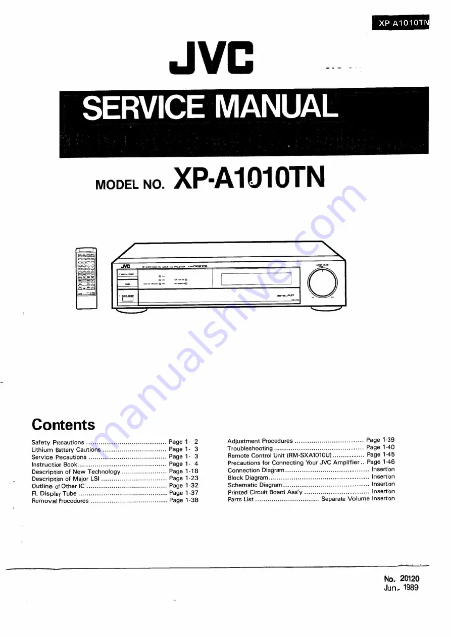
Summary of Contents for XP-A1010TN

Page 1: ... Page 1 45 Instruction Book Precautions for Connecting Your JVC Amplifier Page 1 46 Description of New Technology eeseee Page 1 18 Connection Diagram ccccccecseeeeeeeeeeeee neneeenee Insertion Description of Major LSI eecececeeeenee econeePage 1 23 Block Diagram cceeceeeeeeeeeeceneeneneeeee eeeeneeee Insertion Outline of Other IC eee cece eet eeeee ere eenens Page 1 32 Schematic Diagram 606 FL Dis...

Page 2: ...s barriers and the like to be separated from live parts high temperature parts moving parts and or sharp edges for the prevention of electric shock and fire hazard When service is required the original lead routing and dress should be observed and it should be confirmed that they have been returned to normal after re assembling Leakage current check Electrical shock hazard testing After re assembl...

Page 3: ...nt 1 Replace battery BT601 with JVC Part No CR2032 FT6 nominal voltage 3V only Use of another battery may present risk of fire or explosion 2 Solder within 5 seconds when the temperature of the soldering iron tip is 350 C within 10 seconds when the temperature is 250 C 3 Always use a terminal to solder Never solder directly to the battery body Cautions on Battery Handling 1 Do not pile batteries o...

Page 4: ... field analyzing method You can create your own original sound field by changing one or more of these sound field parameters 1 ROOM SIZE The data on the size of a performance site is programm ed as a Standard value of 1 0 You can change this parameter from 0 5 1 2 to 2 double size room As the value of the parameter increases the apparent size of the performance site gets larger Direct Sound 0 DS t...

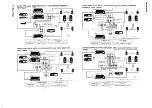
Page 5: ...terminal with TAPE MONITOR With PREOUT MAIN IN Separate amplifier Speaker terminal terminal 4 and switchoperation OPTICAL COAXIAL OPTICAL COAXIAL OPTICAL COAXIAL 6 CHANNEL Fig D Fig E Fig F T DAP MODE switch 6 CH m 6 CH m 6 CH m OPTICAL COAXIAL Eee M1 COM Cm mm Co Selection switch 4 CHANNEL Fig D Fig E Fig F DAP MODE switch 4CH 4CH 4CH OPTICAL COAXIAL Selection switch M39 OM Ms OW mo lLClo USING A...

Page 6: ...TH D A CONVERTER AND PREOUT MAIN IN TERMINAL FOR MAIN ANALOG PRE MAIN amphtier for F QAP FADAP Sound field speakers irra CO player 1 a s PRE MAIN amplitier with D A converter for MAIN eee Main speakers CO player 2 Listener E RIDAP DAP MODE switch Sound field speakers see page7 L COAXIAL N OUT ANALOG PRE MAIN amplifier for R DAP RECIIPLAY Fig E wweeee NOTE Main level cannot de controlled by master ...

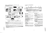
Page 7: ...ime this button is pushed first L ROOM REVERB L 6 channel mode Connect to F DAP out Connect to the amplifier for F DAP Multi mode display B then L ROOM SIZE are displayed and finally the previous display is shown Attention ee MASTER VOLUME L ROOM REVERB Set the degree of sound reverbera i When the digital signal is selected as an input signal the output signal to MAIN OUT of LINE is still an analo...

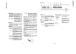
Page 8: ... this button to adjust the front DAP output signal level by using the DOWN v and UP A buttons R DAP LEVEL Push this button to adjust the rear DAP output signal level by using the DOWN v and UP A buttons PROGRAMED PRESET Push this button to load any of the 20 types of preprogrammed sound field data by using the DOWN v and UP buttons The data are not to be lost MANUAL PRESET Push this button to load...

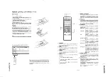
Page 9: ...fe on sound and reverberating REVERB LEVEL 2 Push the button 6 or button How to operate the remote control unit PROGRAM Push this button to load any of the 20 types of preprogrammed sound field data by using Memory Preset Number button 5 6 to set the reverberation sound level HF REVERB Push the button 6 or button to set the reverberation time at high frequency to middie frequency REAR DELAY Push t...

Page 10: ...ce the total level UP Pressing this button rotates the Master Volume Knob CW to increase the total level aoe ys ia OPERATION Refer to the relevant instruction manuals for the operation of the amplifiers Adjust the volume levels of the amplifiers to the same setting Turn down MASTER VOLUME Confirm Connection and Preparations prior to turning on the power to the devices How to use PROGRAMED PRESET T...

Page 11: ...all constructed in West Germany in 1959 accommodating about 1500 persons The ceiling has a complicated structure for sound diffusion The reverberation characteristics are com paratively dead P7 Recital Hatl Small Musical Space Reproduces the sound field of a hall used for classical music recitals This hall with an elfiptic shape is located in Holland and produces an at home atmosphere P8 Opera Hou...

Page 12: ...sh the MAIN MUTE button 8 and F DAP MUTE button to mute the main and F DAP signals and output only the R DAP signals 2 4 INPUT BALANCE display Push the INPUT LEVEL button twice to show the input INPUT LEVEL balance on the display X2 display INFUT BALANCE boson eee FE 2 5 Balance adjustment INPUT BALANCE display On the remote control unit or Push the or button to set the R DAP level to a minimum On...

Page 13: ...d reproduction pattern by changing the parameters and then saving the new sound field pattern in a manual memory location 1 Selecting a program Select a program according to the How To use PROGRAMED PRESET P 18 ex program 3 Symphony Hall 3 Shoebox Tyre Mo iSymehony Hall LFF GkHz Each time the button is pushed the value is reduced or increased by one unit Keep pushing it to continuously change the ...

Page 14: ...rogram No but ton G Push the MANUAL PRESET button Push the DOWN v or UP A button to specify the program No M 3 Symehony Hall 3 Shoebox Tyre 2 Specify a character position using the cursor 1 On the remote control unit Push the CHARACTER but ton to display the cursor On the main set Push the CHARACTER button to display the cursor NLOLOLW CHARACTER display M 3 Symehony Hall 3 AW Shoebox Tyre mas Blin...

Page 15: ...NESS os 2 ouTpoor LIVENESS 2 we PF TkHz 7 kHz 16kHz THRU 15 STADIUM Live iPr 16 kHz THAU REVERB LEVEL CONCERT ROOM SIZE HF REVERB ROOM SIZE REVERB LEVEL 1 2 01 08 1 2 2 RSM SRE O eo 2e SMALL LIVENESS 0 5 2 MUSICAL LPF 1 kHz 6 kHz 16 kHz THRU MEDINA SPACE REVERS LEVEL 0 1 2 17 Mowe SIZED THEATER 2 SPACE REAR DELAY LUVENESS HF REVERB 5 E ROOM SIZE 05 1 2 LVENESS os 4 T6kHe THRU yg MOVIE guate LPF TH...

Page 16: ...Channel a Lar OFF Analog LINE IN Digital LINE IN Analog LINE IN a So FIDAP F DAP re ra ON Ae a W in c 6 Channel 2 m OFF Analog LINE IN Digital LINE N Analog LINE IN FIDAP ee 4 OFF oO z z ON Analog LINE IN Digital LINE IN TAPE PLAY E 2 im cae ae be 4 Channel F DAP 3 aie rc OFF Anatog LINE IN Digital LINE IN Analog LINE IN Pe tp FIDAP r e E OFF 1 a ON Analog LINE IN Digital LINE IN TAPE PLAY cif x 6...

Page 17: ...ing of a live perform ance DAP MODE switch on the rear panel is set to 4 channel in spite of 6 channei reproducing system Unbalanced Volume of F DAP and R DAP amplifiers is lowered Set the DAP MODE switch on the rear panel to 6 Channel Push the INPUT LEVEL button twice to set INPUT BALANCE mode and adjust the balance using the DOWN and UP buttons or the button of the remote controller Turn the vol...

Page 18: ...ensity Their dis tribution canbe plotted as shown in the Distribution Pat tern for Virtual Image Source Locations Figs 2a through 2e The centre of the many circles represents the virtual image source locations the size of the circle indicates DISTRIBUTION PATTERN OF VIRTUAL IMAGE SOURCE LOCATIONS Rear o Fig 2a Location of Sound Source Centre on the Stage Location of Measurement Centre Front 1 18 N...

Page 19: ... according to the size of the room and how its walls and ceiling reflect sound As for the distribution pattern of the virtual image source Right AA je Fig 2d Location of Sound Source Left on the Stage Location of Measurement Centre Front on the 2nd Floor the number of circles representing the reflected sound differs in a live room Fig 3b and a dead room Fig 3c but the basic distribution patterns r...

Page 20: ...kes a few reflections of the highest in tensity from the distribution pattern of the hall and adds the acoustic parameters to the original sound creating the distribution pattern in Fig 4 When these sound signals are reproduced in a listening room having the distribution 1 20 No 20120 Left orchestras and chorus to measure the early reflections and reverberations that would emerge between the speak...

Page 21: ...on patterns occur when the sound source is placed at the centre right and left of the stage Technically this difference is indicated in Fig 6b as drpR and d_pR for the sound source on the right EARLY REFLECTION PATTERNS AND LOCATION OF THE SOUND SOURCE Fig 6a Q w SN UN NS TIF and the left of the stage respectively This difference in distance illustrates that the sound field in a hall changes as th...

Page 22: ... OF THE DIGITAL ACOUSTICS PROCESSOR Analogue O Main Out Analogue 194 Wo Front DAP Out DAP LSI for ER DAP LSI for ER DAP LSI for REV Analogue In Analogue x4 o Rear Digital In DAP Out Reac Master DAP Volume Level Remote Digital Main Out Through Fig 8 BLOCK DIAGRAM OF THE CUSTOMIZED VLSI CIRCUIT CONTROL DATA COEFFICIENT CONTROL DRAM I O AL MULTIPLIER INPUT REG 0 ae IN CRYSTAL O osc SHIFT ry ACC OUTPU...

Page 23: ...l rever high quality that cannot be performed by an analog beration of a hall stage stadium etc by folding the delay system read write of digital sound field data initial reflected sound and calculating reverberation 2 Internal Block Diagram xX x0O oscsO SDINO SCK1 SCK2 2LRCK ESICK ESOCK PERIOO a ee Wow O OIDATA Timing generation circuit Control register Data input circuit Delay shift register Coe...

Page 24: ...cy output terminal Xt clock quarter frequency output terminal 4 SIOCK Data shift clock output terminal for A D and D A converters Internal generation mode LRCK Channel clock output terminal for A D and D A converters Same as above 2LRCK Double LRCK frequency clock output terminal Same as above ESICK Shift clock input terminal for fetching of L ch and R ch serial data T External input mode Schmidt ...

Page 25: ...ress strobe output terminal RAS External DRAM low address strobe output terminal WRITE External DRAM read write pulse output terminal OE External DRAM enable pulse output terminal IDATA Interface period pulse input terminal Schmidt input ICK Interface clock input terminal PERIOD Interface period pulse input termianl Reset signal input terminal Equipped with a built in pull up resistance fo Power s...

Page 26: ...RAM and processes input output data to save manual programs and contro muting and puts The MN188321 has a switchable two speed volume system clock using two built in oscillation circuits 8 2 Sketch drawing x 2 2 o o Vm ES Wie a a or aagaato ng c Met oe See See e eee eee F o nme non SQ28536es2a OM Ok FeE I I a Ssag0ogboaorFr oor SSZESPPUHYErEE eee osoe He Sy 3 lo1 PLS islis lsL SLI fs PS fs CcS2 cs...

Page 27: ...ERIOD 2 To DSP PERIOD PERIOD 1 STB 3 39 40 41 42 43 STB 2 ie To TC9176 STROBE Terminal 44 STB 1 ie 4s KEY It t Key input 46 KEY 10 47 FS 1 I FS 32 44 1 48 bes input FS 1 H L H 48 FS 0 FSO H L L pe 49 VOL DAP 1D O To DSP TC9176 DATA 50 INH 51 VOL DAP ICK ie 52 MUTE IND ie 53 RMO 3 oO Outputs Level H when receiving signats from the remote controller ie oO Oo inhibit input power souce detection TO DS...

Page 28: ...ming clock left channel and right channel The terminal for output of subcodes and can fetch subcode data Outputs the sampling frequency copy enable presence of emphasis and presence of errors of transferred audio signals Re outputs the previous audio data if a digital au dio interface format signal error is detected 3 Internal block diagram 4 Vvss2 6 X1 J oO 5 x0 Crystal oscillating circuit Phase ...

Page 29: ...rcuit check terminal L 12 BGO 19 Timing clock of the signal output from the DO terminal 13 SYNC 14 Vssi 15 L R 16 DEF Synchronizing singal System ground 0V Indicates that L ch and R ch data is output from the DO terminal at Level H and L respectively H Indicates that input data has been emphasized L Indicates that input data has not been emphasized 16 bit data output Indicates that data is output ...

Page 30: ...nd small size Note The MASH is an over sampling A D conversion technique to enable high S N ratio by connecting 1 bit quantizers in multiple stages over three stages without a trimming process MASH was designed by Nippon Telephone and Telegraph Co NTT tional standard one consequently it can reduce the total power consumption of the entire A D conversion system The MN86081 can be used in digital AV...

Page 31: ...lear circuit operation at L 512FS input terminal Digital ground terminal Digital power source terminal 5V Digital ground terminal Digital power source terminal 5V Analog ground terminal Analog power source terminal 5V mn Analog section reference voltage input terminal 1 5V Analog ground input terminal 2 5V Analog input terminal A VoD Analog power source terminal 5V A Vss Analog ground terminal DA ...

Page 32: ...2 fa a a a g f a 2 AOQ A10_ Address input terminal WE Read write control input terminal OE Output enable input terminal ci Gi CE Chip enable input terminal 0 T ro nN 3 o 5 Q a DO D7 Data 1 O eC tS OF ie Vcc GND Power source terminal M VC4096 IC604 GATE ARRAY FOR 16 Bit ADDER Hiei en teteenetale tatelahteats SDIA1 SDIB1 SDO1 SDIA2 SDIB2 SD02 iG Sle 2 BIBIEIE FSLR FS sampling frequency input g 2 8 P...

Page 33: ...l output terminal outputs OUT the low level during reset and the high TC74HC138P IC801 3 TO 8 LINE DECORDER level while reset is released Truth value table ENABLE SELECTED QUTPUT G2A me x o xl N w x el a N NONE NONE NONE Yo Yr Y2 Y3 Ya Ys Ye Y7 xloj ejcicl er r ns rile jrle erie lrie e Pole XCjpUoyTpLy Tl T Tlrl cizsy zr LPL yULyeyTi Lie coclry cls XpLCpcryLl Tiler cycl erly rizr Ba Be ak Bi a Be ...

Page 34: ... a oie V A L ouT1a 5 2 AMP INB ae Soil MalanScanSAD me four se i ee GNDJ 8 fe OUT 38 8 GND Constant Current Source OOO M O AMP AMP OUTS8 OUT48 OUT3B8 OUT28 OUT18 CH2 ouTB INB CONNECTION GND LED current limit resistance Vcc PIN NO CONNECTION Output GND Vcc GND Case Case TC74HC157P IC708 QUAD 2 CHANNEL MULTIPLEXER Truth value table INPUTS OUTPUT STROBE SELECT y 0s7 bd L L H L H L L H Don t care 1 34...

Page 35: ...a eccear INPUTS OUTPUTS 4 CLOCK CLEAR QA aB ac aD reels p Jeon 5 H ee a oe 6 vacfs foj208 a COUNT UP 8 NO CHANGE 9 1 oof 9j2ac GND a 200 ETETETTITITeerreeerer eH S ToerttrrrrzwririresTrere DBoiretrtrrrirtreretir FREQ CONTROL PHASE COMPARATOR Phase comparator timing chart SIN PHASE OUT oe ed Q _e Ost AIN No 20 2 1 35 ...

Page 36: ...TPUT ENABLE rola INHIBIT 20 5 INHIBIT OUTPUT ENABLE a Qa afle LS L H L H JIL LW OUTPUT ENABLE JL LW L H INHIBIT GND Bo oA X Don t care Cx Rx External parts installation terminal NJM3404S IC710 DUAL SINGLE SUPPLY OPERATIONAL AMPLIFIER PIN ARRANGEMENT vt A OUTPUT A INPUT A INPUT V B INPUT B INPUT B OUTPUT Vt OBNOARWN 1 36 No 20120 ...

Page 37: ...ers two lines Character display fOorm eeeeererere ees 5x 7 dots Display range seceeeeesseeeeeeeeneee 100 2 x 16 mm Display character SiZ seeeeeeees 3 3 x 5 05 mm Display character pitCh ssseseeeereeeeeees 5 1 mm Fluorescent COlOr 2ceeeeee cereeeeeeeneees Blue green 4 Function This module is equipped with data write command and functions are write status read and reset functions The control lines F...

Page 38: ...d pull out the door ass y 3 Removing the digital interface PCB ENB 087 1 1 Remove the top cover 2 Remove four screws on the rear panel 1 38 No 20120 Motor Volume PCB BRON Knob ring 1 re Front Panel Mounting 4 Removing A D D A PCB ENP 019 1 Remove the top cover and the digital interface PCB 2 Remove 6 screws and 3 screws on the rear panel 5 Removing the digital signal processor PCB ENB 09 1 1 1 Rem...

Page 39: ...the 20 kHz LPF and 400 Hz HPF of the distortion factor meter Use a digital signal of 1 kHz and O dB output from a digital audio signal generator or DAT as the test signal Note 2 MODEL 1506 manufactured by Leader Flectronics is a recommended digital audio signal generator ENB 087 1 2 MSB distortion factor adjustment of A D section 1 Mode setting Select PROGRAM 1 and press the TEST switch SW702 on t...

Page 40: ...ut Is digital data output NO from J103 pin YES Is digital date output NO from P607 Pin YES Is digital data output from NO pins and of P103 YES See D A Circuit procedure 1 40 No 20120 2 Turn the DIGITAL DIRECT MODE TAPE MONITOR and DAP RECORDING off 3 Set the MASTER VOLUME to maximum See A D Circuit procedure See Digital I O Circuit procedure See DSP Circuit procedure ...

Page 41: ... signal output from C407 pin YES Check the patterns related to IC408 and J103 NO NO NO NO NO XP A1010TN Check 1C503 and its peripheral parts Check 1C502 and its peripheral parts Check IC404 IC403 and their peripheral parts Check IC405 and its peripheral parts Do 1C407 pins and receive the LRCK and BCLK signals respectively NO YES 1C407 is defective Check the Clock List No 2020 1 41 ...

Page 42: ...ins receive digital data YES s digital data output from IC606 and IC607 pins YES s digital data output from pins and of C604 NO YES Is digital data output from pins and of 1C604 NO YES Check the pattern output from IC604 to P103 NO NO Check the related patterns output from P603 to iC 707 and check soldering C707 is defective Check the pattern output from J603 pin to IC606 and IC607 the clocks of I...

Page 43: ... waveform NO YES Does IC 207 pin generate a waveform NO YES Does IC505 pin generate a waveform NO YES Check the patterns output around Q509 XP A1010TN Are LRCK BCLK and DFCK signals in the normal condition YES NO Check the Clock List 1C201 is defective Check IC203 1C202 and their peripheral parts Check IC204 IC205 and their peripheral parts Check IC 209 IC207 and their peripheral parts Check IC 21...

Page 44: ...Name X tal 512 fs IC602 2 256 fs 12 288 MHz 81 38 nS IC602 IC605 606 607 IC708 1C709 3 64 fs direct mode Name BCLK BCLK1 64 fs DIR DSP in digital 3 072 MHz 325 5 nS 1C701 in digital mode IC708 in digital mode IC 605 606 44 in digital mode 4 32 fs digital filter Name BCLK BCLK 32 fs A D DSP ADDER 1 536 MHz 651 0 nS 1C406 407 IC605 606 607 1C604 1C201 301 1C707 IC708 1 fs LR clock digital filter Nam...

Page 45: ...x2 455KHz LISTEN lSOURCE SPREAD PLAY room REVERB POINT a YL IMANU PRO PARA MEMO AL GRAM METER A RY hay a ap BZ a Iw YY a MAIN MASTER MAS Tee MUTE vp bOWN ms m cp cy cp y OY 03003 03002 ISS 270 x2 Disassembly 1 Remove the screw in the middle of the backside of the remote control unit 2 Slide the bottom panel downwards to take it off No 207 09 1 45 ...

Page 46: ...ard to connection methods please refer to page 11 in the Instruction Book AMP AMP DAT AMP TAPE MAIN UNIT SOURCE MONITOR MONITOR DIGITAL SELECTION SW Sw DIRECT SW 10m Sec DIGITAL ON AX Z1010TN ANALOG Om Sec 48kHz 44 1kHz 32kHz BIBLES oN 140m Sec i Sec ee Sec Om Sec AX Z911BK ANALOG ON or OFF DIGITAL ON Om Sec AX Z711BK ANALOG Om Sec In this case main level cannot be controlled by master volume 1 46...

Page 47: ... Q805 Q603 40V 5V 12V 12V BACK UP 5V T MON DAP REC Bata R DAP IC7I3 DIG ANA LITIUM outo DE EMPHASIS SW BRCK UP 5 BATTERY swso a sREV Sweo2 Sweo3 Sw804 Saas pale Soon Q60 l sw70 O O SPROI O h Pi Topt coax Isw805 gweoe sweo7 sweoe b 100 OF SW is a paras pone ae 8 5 10 00 ROOM o O O O IC6l4 a Sw809 lewaiot swelld Swale Die 2 manu DRE S No RESET DIREI cT O O swai3 f t RM 80 OPTICAL REMOTE SENSOR RM SX...

Page 48: ...am Digital Interface PCB ENB 087 A D D A PCB ENP O19 AC Primary PCB ENB O9I 2 Digital Signal Processor PCB ENB O9I I PLL PCB ENB 087 2 ENB O91 4 Motor Volume PCB Front PCB ENB O9 I 3 O Mute Indicator PCB FL CNI ENB O9I 5 No 20120 ...

Page 49: ...na g FS a TO ENB O9 FROM ENB 091 1C5031172 44 IN auc T e UNF F ICSIOB 5 R582 10K te 47S SO aad 6 8x FX 10515 PSUR GAS FUG INPUT LEVEL CONTRO eet te a 1c2071172 Ql R A 10 y I6V Esc v0 are RNIOUNFF __ J foojor 3 Leh O Ug Res 47 R57 SS 5676527 T gsez 1 507 272 220K a TAPE REC sku 220 OP 7 72 CI21 0 00 L574 DI R568 Z cS28 ole Chasis_J C553 001 IC503 IC507 VC4580LD DIOS Cus Ol T D110 POWER SURPLY DIOS ...

Page 50: ...2 1OP CH 0201 D202 D205 D206 D301 D302 DSO 0604 D 15 D506 508 Jissas IC207 1C208 IC2I0 1 305 IC310 IC3I IC3I2 ycassotp a 1C402 IC408 1C 405 C 406 1C203 2 2 402 IC 4054 nor useD 1C503 WIC507 ati DIOW W D2 ERAIS 02 C55I C553 O 0ly L569 L574 L507 L508 L519 L520 L553 L558 EM 201 EM401 EM402 EQF O60 222 b3 sun AV DIV 0 2mS DIV Approx 4 1Vi KFRB ___ ENP 019 R314 R316 1 306 I 2 a 2vi0IV 0 2mS DIV XP A101...

Page 51: ...YI3 J swaoi sie Ppa ets kev a vE0l 816 __ hpzi3 Hi7 _Kevos evo2 tis Fane u ino onhis REVI OIG ANE BaP REC ist_ 5 6v a oe is _ 5 6v rerio bo CNT OD CERRIND Poea cee ENB O9I 3 SSS ee SSS SSS SSS SSS SSS ee HH EEE SSS SS sca Reece oc ENB O9I 1 BN es Se PIOS 170 ENP O1S7 TO ENB 087 i Fes h 2 xtai256fs_ F St 5 A 3 T MON 3 4 DiG ANA 15 16 m S k qT cram el ogo TUT CE eer el eae tOEA Serres Erehs p138t33 ...

Page 52: ...ne 74 eco Liotajaal Cols aNa ig 709 R7I7 OpAev 47K ae 0 iN Juzo3 LINE C705 47 2V D713 R718 4 R720 MTZ5I 75 0 E mu O out 1C70611 2 FR TC74HC 123P 9 33p T70 R722 10 R72 i ie d ICrOSEVE aot ae 6 cyst 1702 2794 Icom C707 47 25V 33P C706 44 25V C732 0 01 eran TC74HCO4P 1c704 EM 705 708 EQFO6O0I 222 T Gore ip VOL DAP_ID PERIOD3L s LRCK oe ae ee ee ee ae Scie a ...

Page 53: ...H geiiciie o sewity Brees ar aces beeA hasan Lela hearts eS A ea eT if an onast f Teamuit Pe psithioeqe 4 eadlt gti ert ery ot ge 59 fnstals griger ait s plead ig the art ee neta yes attec Cs Tiled DIGITAL SIGNAL PROCESSOR P C BOARD etc ENB 091 DR itail ses sebuetue suse oytitay pel wm tt Cte ot er ee E i tt UE o a on te ie all No 20120 DIGITAL INTE VOLTAGE SEL ...

Page 54: ...AL INTERFACE P C BOARD etc ENB 087 NGE SELEC IRP C BOARD TPS 266 ...

Page 55: ... AGE SELECTOR P C BOARD TPS 266 E AL INTERFACE P C BOARD etc ENB 087 ...

Page 56: ... Continental Europe CcOOlAy cooz 0 01_ AC400V 0 022 af AC250V _ ENB 0916 2 7 U other Areas 05 0 01 AC250V coo2 0 022 ACIIO 120V NB O91B 2 220 240V 50 60Hz A for Australia AC240V 50Hz G for West Germany AC220V 50Hz L__ENB 09IC 2 FLOOI 2OWORDS x 21iNE Sx 7DOT FL MODULE OOOOO0UOOO00D0O000000000 ...

Page 57: ... signal The waveform and voltage value shown in the photo was measured in TEST 1 mode by inputting a signal of 1 kHz 2 Vrms to the analog LINE IN indicates the B line indicates the B line Parts marked with A and those in the darkened area am are parts for safety Be sure to use one with the specified part number This is the standard schematic diagram The schematics and circuit constants are subject...

Page 58: ... 266 IC Voltage Selector PC Board Ass y ccccccccecccccccccsssececccccsceceesueueecccccecs 2 9 ENB 091 LJ Digital Signal Processor PC Board ASS Y ccecccceccecesecseccessesteveveececces 2 10 ENB 087 _ Digital Interface Receiver PC Board ASS y ccccccccccssscceseeeececcssccccsecees 2 13 Acessories Lists 5 22 sccestaserdnvea selec eke evs ccendecsuddaocatelvadaeu ides eadiesdidesteneconitaliliacdons 2 ...

Page 59: ... P A1010TN Exploded View and Parts List attached part k indicates 2 2 No 201 20 ...

Page 60: ... E304889 002 E304890 006 ETP1020 32JA ETP1020 32HA ETP1020 32EA ETP1020 32EABS E72606 001 E65389 004 E 305514 001 Front Panel Assy Front Panet Front Base Ass y Sub Panel Window Screen Plate Hinge Hinge Hinge Holder Hinge Holder Magnet Door Ass y Speed Nut Spring Indicator Indicator Indicator Indicator FL Screen Push Button Ass y Screw Volume Knob Plastic Rivet Felt Spacer Felt Spacer Metal Cover S...

Page 61: ... 011 Rear Panel Except J C U 303260 196 Rating Lable E EF G 43 E75141 001 Caution Label J E73273 003 Special Screw E73273 002 Special Screw U E73562 003 Special Screw Except BS BS QHS3771 108 QHS3771 108BS QMP 1480 200 QMP7600 200 QMP3900 200 QMP2560 244 QMP9017 008BS Cord Stopper Cord Stopper Power Cord Power Cord Power Cord Power Cord Power Cord NOD A Safety Parts The Marks for Designated Areas ...

Page 62: ...s ESS 2 Se 310Way a ql 608MS 23 9 a 423410 910 ac be fy 7 160 8N3 O ars Ley YA YOLOW res 2 Qre c610 ID e i e fo FyOu e if 2 1606 SH 7 nen 1S oor 90000 6180 4160 i see sx usa LES econ ie q NS Ler So Fico bLY9 dSa em 4298 i Q 3 r oS o m S a e wear 3 3 22 eee a mas J60S ty FL wees 41 W620 Soe 8 fay uw oO of RS B xy pad RG Oo Sl ku D ipo oe VO EA O z Q So z 4 D So a xz 4 U 4002 Z 160 8N3 GIOdNI OL 4 t...

Page 63: ...TSUSHITA 188133 SILICON ROHM Q511 28D1302 S T SILICON MATSUSHITA y 07 188133 SILICON ROKM Q512 28D1302 S T SILICON MATSUSHITA 18 133 Q513 DTC144ES SILICON ROHM 18S133 2SAS64ACR S SILICON MATSUSHITA OTCI44ES SILICON ROHM DESCRI iy camts ae2 LC4966 LC4966 VC 4580LD VC4S80LD 2 6 No 201 20 SANYO SANYO DAINICHI IDAINICHI QCF21HP 103 0 01MF CERAMIC MAKER QETB1UM 227 220MF j63V ELECTRO QETB1HM 226 22MF S...

Page 64: ... QCBBIHK 224 220PF SOV CERAMIC of CC21EM 473 O O047MF 25V ICERAMIC ie C508 Q CBBIHK 221 220PF SOV CERAMIC C312 QETB1AM 107 OOMF i10V ELECTRO C509 QETB1HM 475 4 7MF SOV JELECTRO C313 ETBLAM 107 MOOMF i10V jELECTRO C510 QETB1HM 475 4 7MF SOV ELECTRO C315 QCSB1HJ 470 4 7PF Sov CERAMIC C515 CBB1HK 221 220PF 50v CERAMIC jG 16 QCSBIHI 470 PPE ed POV CERAMIC od 4 G326 QCBBIHK 224 220PF SOV CERAMIC oo C31...

Page 65: ...BON CARBON CARBON CARBON CARBON CARBON CARBON CARBON CARBON Ic ARBON CARBON CARBON CARBON CARBON CARBON CARBON CARBON CARBON CARBON ICARBON Ic ARBON CARBON CARBON CARBON CARBON CARBON CARBON CARBON an Gone CARBON CARBON j CARBON CARBON JCARBON CARBON CARBON CARBON ICARBON CARBON CARBON CARBON CARBON ICARBON CARBON CARBON CARBON CARBON CARBON CARBON CARBON CARBON CARBON CARBON JCARBON J CARBON CARB...

Page 66: ... EMV7122 003 CONNECTOR J501 EMNOOTV 40BA 4P PIN JACK J502 EMNOOTV 408A 4P PIN JACK J 2503 EMNOOTV 408A J504 EMV7122 003 J505 EMV7122 003 CONNECTOR J506 EMV7122 003 CONNECTOR J507 EMV7122 003 CONNECTOR 9308 EMV7122 003 1509 EmV7122 003 L507 EQL4004 3R3 INDUCTOR L508 EQL4004 3R3 INDUCTOR L519 E L4004 3R3 INDUCTOR vee 5 20 EQL4004 3R3 US39 EQL4Z006 3R3 L540 E L4004 3R3 INDUCTOR L555 EQL40046 3R3 INDU...

Page 67: ...g R221 C4l a 0 oO 0 mas Oto CER eae Oe cre Oto FO ls R106 9 2 77 rh Fo Se tN S0080 oS AO an Mion BBs cos 3 Aa at ie 2 le tr Cet ae 2d 00 5 OL 370 10 can Rey will 0 en 00500 3 w e ace U of oft ad 6 C929 mtn bg 00H eee ak 4Go jere O 20d Es ea A BIAS Sod ne Covey Ae S waco lo OQ vy oa dese z as 7 O08 5103 os Gray w h 2 i 10 04 of 39 i 7 é coeb CH ree 00 Be ie ey Re i 1 oO wore 8 CO BIR con S 10 wu3 S...

Page 68: ... 475 4 7MF SOV jELECTRO HESOd VELOSSCOOE ig HOSHTBR hoo CHOW GeThauMcece a ae OWS REEGTRE IC607 VC4097 003 1 C TOSHIBA fo fd C808 QETBIHM 475 0 ATM POV ELECTRO 1C608 TMM41464AP 12 LC TOSHIBA C809 CZ0205 155 4 SMF 25V CERAMIC C609 TMM41464AP 12 1 C TOSHIBA QCZ0205 155 CERAMIC C610 TMM41464AP 12 Tate TOSHIBA QETB1AM 107 ELECTRO 1C611 TMM41464AP 12 1D C TOSHIBA kC612 TMM41464AP 12 I C TOSHIBA IC613 T...

Page 69: ...LAT WIRE FWSOS EWR23C 30OLN FLAT WIRE FW506 EWR23C 3OLN FLAT WIRE em FW507 EWR23C 3OLN FLAT WIRE FWS0al EWR23C 30LN FLAT WIRE FW509 EWR23C 30LN FLAT WIRE FW601 EWR34B 13LST FLAT WIRE FW602 EWR33B 25LST FLAT WIRE is SwoO1 SP4C11 01 PUSH SWITCH A I wOO4 SP4C11 E01 PUSH SWITCH 8 SWOO1 SP4C11 E01 PUSH SWITCH SWOO1 SP4C11 E01BS PUSH SWITCH oBs sw801 ESP0001 018 TACT SWITCH me sW802 ESPO001 018 TACT SWI...

Page 70: ...AI5S ra wa wn2 F Tr Ee im CO et ls 2 _ Je fs cn ls L80 8N3 V O AP6 LEP wL 7849 LA Ss O coy 2014 J701 R705 me O 1 WALISIG 29LK TSA yOL2 3 3 owrary RA 0ud 3 24 1703 pie ori 30 O08 Os 0 af 3 w6 ae 2A m8 2 2 is03 o 2 re W790 3 aR U 2 3 3 3 i3 re 0 784 7 wes c709 ox on m ene as 0707 mop Ry ot 0708 e 0709 123 20 m ono wi _ P oS DES aR saa P RR RRO OQ K7O1 R736 AIM RIZ2 RIIO RIB FB0000000000 R737 R738 R7...

Page 71: ... 6W ICARBON QRO01675 473 7K 4 6W ICARBON QRD167J 820 82 4 6W ICARBON DIODES _ RD167J 75 PART NUMBER DESCRIPTIOWNJAREA QRD1E7I oo Q RD167J 820 82 76W CARBON eee A RD167J 100 10 h 6wW ICARBON ERA15 O2L19 SILICON KYOUDOU RD167N 750 D702 188133 ISILICON rmowm fup R724 QRDI674 104 D703 185133 SILICON ROHM QRD167J 104 D704 188133 SILICON ROKM QRD167J 221 0705 188133 SILICON ROHM p coched GRO Letdseet ef...

Page 72: ... E04056 RM SXA1010U UM 4NJ 2PSA EWP302 013K TOCP172 1MB JV E66416 003 E41202 2 300196 032 300196 032B PART NUMBER ACK DESCRIPTION CIRCUIT BOARD OPTICAL JACK 2P PIN JACK 2P PIN JACK CONNECTOR INDUCTOR ITNDUCTOR INDUCTOR INDUCTOR INDUCTOR INDUCTOR CONNECTOR CONNECTOR CONNECTOR FILTER PILTER FILTER PILTER PILTER Instruction Book Instruction Book Inatruction Book Warranty Card Warranty Card Warranty C...

Page 73: ... Materials and Part Numbers E300196 094 Except BS E300196 094B BS E75594 001 Protect Sheet E26059 001 Packing Pad E75003 002 7 Cover oS 7 S Is PK XPA1010T NE E300383 055 Packing Case E26059 002 Packing Pad 2 16 No 20120 ...

Reviews: