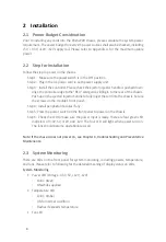
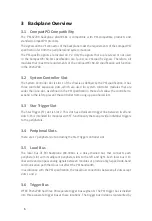
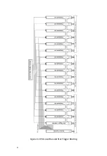
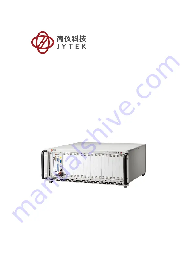
JYTEK PXI-62700, User Manual
The JYTEK PXI-62700 offers cutting-edge technology in a compact design. Unlock its full potential with the comprehensive User Manual available for free download on our website. Master every feature and function of the PXI-62700 with this detailed manual, ensuring optimal performance for your applications. Download now at 88.208.23.73:8080.
Share
Download


Reviews:
No comments
Related manuals for PXI-62700

SC827HD-R1400B
Brand: Supero Pages: 82

cRIO-9148
Brand: National Instruments Pages: 23
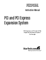
PEX2PCIE4L
Brand: StarTech.com Pages: 10

ION219 Series
Brand: Lantronix Pages: 36

apollo 4510 gen9
Brand: HP Pages: 68

BladeSystem c7000
Brand: HP Pages: 80

Apollo a6000
Brand: HP Pages: 49

7893
Brand: Lenovo Pages: 2

AMOS-5110
Brand: VIA Technologies Pages: 2

Modular Matrix 38250
Brand: Lindy Pages: 8

LCP13
Brand: Comet Models Pages: 6
IPC-616
Brand: Advantech Pages: 22

IPC-610BP-30XF
Brand: Advantech Pages: 24
IPC-610-H
Brand: Advantech Pages: 26

IPC-603MB
Brand: Advantech Pages: 30
AIMB-C300
Brand: Advantech Pages: 22
IPC-3012
Brand: Advantech Pages: 30
AIMB-C200
Brand: Advantech Pages: 28


