background image

KK52/KK102

USER’S MANUAL

English

Kobra

Summary of Contents for Kobra KK52

Page 1: ...KK52 KK102 USER S MANUAL English Kobra ...

Page 2: ......

Page 3: ...NG 8 5 WARRANTY 8 6 SAFETY 8 7 PHYSICAL 9 8 REAR PANEL 11 9 COVERAGE 12 10 WIRING 14 11 PROTECTION CIRCUITRY 14 12 ACCESSORIES AND CONFIGURATIONS 15 K Base2 15 K Fly2 16 K Joint2 16 K Wall2L 17 K Wall2 17 K KCluster2 K PCluster2 18 K Foot2 18 K KStage2 K PStage2 19 13 SERVICE 19 14 Specifications 20 ...

Page 4: ...KK52 KK102 REV A 4 ...

Page 5: ...ngerous voltages RISK of electric shock K array declares that this device is in compliance with applicable CE standards and regulations Before putting the device into operation please observe the respective country specific regulations WEEE Please dispose of this product at the end of its operational lifetime by bringing it to your local collection point or recycling center for such equipment This...

Page 6: ...KK52 KK102 REV A 6 ...

Page 7: ...ble impedance 16Ω 64Ω for the KK52 and 8Ω 32Ω for the KK102 Set to 64Ω up to eight KK52s can be powered via a single amplifier channel simplifying installation of wider distributed installed systems Kobras are able to reproduce the entire vocal frequency range with excellent intelligibility starting from 150 Hz Integrating powered subwoofers from K array s Redline series KMT12 KMT18 KMT21 ensures ...

Page 8: ... is not liable for consequential damages This warranty is exclusive and no other warranty is expressed or implied This warranty does not affect your statutory rights 6 SAFETY Only install the speaker in a location that can structurally support the weight of the unit Doing otherwise may result in the unit falling down and causing personal injury and property damage Professional loudspeakers are cap...

Page 9: ...REV A KK52 KK102 9 7 PHYSICAL 8 1 cm 50 cm 12 cm 5 9 cm 3 19 19 7 4 72 2 32 weight 2 3 kg 5 07 lbs KK52 ...

Page 10: ...KK52 KK102 REV A 10 weight 4 8 kg 10 58 lbs KK102 100 cm 39 4 8 1 cm 3 19 12 cm 2 75 cm 2 75 cm 4 72 1 08 1 08 5 9 cm 2 32 ...

Page 11: ...A10 Please refer to your amplifier s specifications to select the correct speaker impedance for your configuration 3 Coverage switch Selects the vertical dispersion of the speaker Flood coverage sets a wide vertical diffusion angle of 60 KK52 35 KK102 Flood coverage is suggested for single speakers in diffused image 1 short throw applications to obtain maximum diffusion with a minimum footprint Sp...

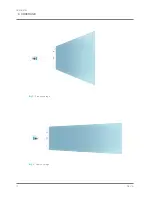
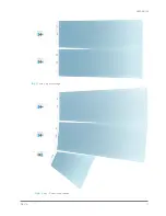
Page 12: ...KK52 KK102 REV A 12 9 COVERAGE Img1 Flood coverage Img2 Spot coverage ...

Page 13: ...REV A KK52 KK102 13 Img3 Array spot coverage Img4 Array Downfill application ...

Page 14: ...or 2 and 2 pins such as 1 and 1 are directly wired from one socket to the other so signal can pass through multiple KK modules without additional external cabling Speakers are electrically protected from brief power overloads within a reasonable range Overloading the speaker for extended periods of time can cause damage so proper system design is strongly advised ...

Page 15: ...rs For proper installation and operation use with K Foot2 and K Joint2 TIPS where possible screw the feet of K Base2 to the ground Before connecting KK KP series speakers to a K Base 2 check the stability of the ground where K Base 2 is to be placed K Base 2 should not be placed in a zone accessible to the audience Take maximum precaution in highly windy locations especially when screwing the K Ba...

Page 16: ...es or to another KK KP speaker with continuously variable angle 10 10 K Fly2 Flying accessory set for KK KP speakers For proper installation and operation use with K Joint2 K Joint2 Consult the dedicated product manual for safety information and operation details WARNING K Joint2 ...

Page 17: ...02 it can be screwed to the internal or the external screw holes depending on the width of the desired angle Wall mounting accessory for KK KP speakers with full 3 dimensional tilting features K Wall2 K Wall2 is designed to be screwed directly to the mounting screw holes of KK KP speakers When used with KK102 the K Wall2 can be screwed to either internal or external screw holes depending on the wi...

Page 18: ... 2 K PCluster 2 comes in a set of three different models one with no angle between the three hanging speakers one with a 30 angle between speakers one with a 60 angle between speakers 35 mm pole mounting accessory A 35 mm threaded pole is included for connecting additional K array products such as KMT subwoofers or K Base2 0 30 60 30 60 0 ...

Page 19: ...red to describe the problem clearly and completely 3 If the problem cannot be resolved over the phone you may be required to send the unit in for service In this instance you will be provided with an RA Return Authorization number which should be included on all shipping documents and correspondence regarding the repair Shipping charges are the responsibility of the purchaser Any attempt to modify...

Page 20: ...l range 8 x 2 Neodymium magnet with 0 75 voice coil Power Audio Input Connectors 2 x 4 pin Speakon Wiring 1 1 signal IN LINK 2 2 through Selection Switch Vertical pattern Spoot Flood Impedance 16Ω 64Ω Physical Dimensions 8 1 x 50 x 5 9 cm 3 19 x 19 7 x 2 32 Weight 2 3 kg 5 07 lbs 1 Maximum RMS applicable power for a musical signal the reference signal is the one proposed by EIAJ standard 2 Measure...

Page 21: ... x 2 Neodymium magnet with 0 75 voice coil Power Audio Input Connectors 2 x 4 pin Speakon Wiring 1 1 signal IN LINK 2 2 through Selection Switch Vertical pattern Spoot Flood Impedance 8Ω 32Ω Physical Dimensions 8 1 x 100 x 5 9 cm 3 19 x 39 4 x 2 32 Weight 4 8 Kg 10 58 lbs 1 Maximum RMS applicable power for a musical signal the reference signal is the one proposed by EIAJ standard 2 Measured 4 mt t...

Page 22: ...KK52 KK102 REV A 22 ...

Page 23: ...l are furnished for informational purposes only Hp Sound Equipment s r l assumes no responsibility for any errors or inaccuracies that may appear in this manual Hp Sound Equipment s r l reserves the right to make modifications without prior notice ...

Page 24: ...K array s r l unipersonale Via Paolina Romagnoli 50037 San Piero a Sieve Firenze Italy tel 39 055 8487222 fax 39 0558487238 e mail info k array com www k array com UMC029AA01ENA ...

Page 25: ...KMT12 KMT18 USER S MANUAL English ...

Page 26: ...KMT12 KMT18 REV A 2 ...

Page 27: ...TAGE REQUIREMENT 11 8 3 CURRENT REQUIREMENT 11 8 4 REAR PANEL 12 8 5 TOUCH SCREEN FUNCTIONS 14 8 6 AUDIO INPUT CONNECTOR WIRING 15 8 7 AMPLIFICATION AND PROTECTION CIRCUITRY 15 9 K Framework 16 9 1 SYSTEM REQUIREMENTS 16 9 2 Installation and set up 16 9 3 User Tabs 19 INPUT TAB 20 ROUTING TAB 21 DELAY TAB 21 OUTPUT TAB 22 10 SERVICE 23 11 Specifications 24 12 Declaration of conformity 26 ...

Page 28: ...KMT12 KMT18 REV A 4 ...

Page 29: ... of electric shock K array declares that this device is in compliance with applicable CE standards and regulations Before putting the device into operation please observe the respective country specific regulations WEEE Please dispose of this product at the end of its operational lifetime by bringing it to your local collection point or recycling center for such equipment This device complies with...

Page 30: ...KMT12 KMT18 REV A 6 ...

Page 31: ... KMT12P or KMT18P To optimize performance the on board DSP includes up to 40 programmable presets The first 8 have been designed by K array the additional 32 slots can be used to create save and store personal presets using the K framework software The KMT series unique four corner port configuration provides symmetrical back loading to the speakers for extended bass response with very low distort...

Page 32: ... care Hearing loss is cumulative and can result from extended exposure to levels in excess of 90dB Always use loudspeaker systems in a safe manner Never stand close to loudspeakers driven at high volume Only install the speaker in a location that can structurally support the weight of the unit Doing otherwise may result in personal injury and property damage The system should only be suspended by ...

Page 33: ...REV A KMT12 KMT18 9 7 PHYSICAL 32 5 cm 43 5 cm 33 5 cm 12 91 17 13 13 19 weight 15 6 kg 34 39 lbs KMT12 ...

Page 34: ...KMT12 KMT18 REV A 10 61 cm 46 5 cm 47 5 cm 24 02 18 31 18 70 weight 27 6 kg 60 85 lbs KMT18 ...

Page 35: ... continue to operate safely without interruption provided the AC voltage remains within 90 135V or 190 250V 230V at 50 or 60 Hz Please verify that your AC mains connection is capable of satisfying the power ratings for the device CAUTION Do not connect the system to AC power mains exceeding 250V Doing so will cause significant damage to the device and create serious risk for users The KMT12 and KM...

Page 36: ...red by a K array loudspeakers system is the sum of their maximum continuous RMS current We recommend allowing an additional 30 above the minimum amperage to prevent peak voltage drops at the service entry 410VA 10 sec 2200VA 1 sec KMT12 KMT18 max continuous apparent power VA 8 4 REAR PANEL 1 2 3 4 5 12 13 14 15 16 17 18 19 19 20 6 7 10 11 9 8 ...

Page 37: ...put providing two channel digital audio from AES EBU Input at a sample rate of 48 kHz This output cannot be processed or controlled via the K Framework software 11 REMOTE RS485 Link Input XLR input for connecting the KMT from another RS485 device in a K Framework network RS485 Link Input can also be used to connect a computer running the K Framework software requires K USB USB to RS485 adapter 12 ...

Page 38: ...ng of the four input channels to the three outputs Subwoofer Speaker Out and XLR DSP Out as well independently set output volume and delay for each output The delay values set in the Routing pages are summed to the global delay assigned on the Delay page The arrow buttons on the top right corner of the screen provide access to individual Routing pages for the Subwoofer Speaker Out and XLR DSP Out ...

Page 39: ...o CH1 Line Parallel Out male balanced XLR To create your own audio cables please use the following wiring diagrams hot XLR connector grd cold hot grd cold 2 1 3 2 1 3 INPUT PARALLEL OUTPUT The KMT12 and KMT18 are powered by a 2 channel digital amplifier with 1 050 W output power per channel EIAJ test The KMT12 and KMT18 s amplifier functions including crossovers equalization phase response and dri...

Page 40: ...K Framework software please navigate to the K array Software Download page located at http usa k array com en download software html Download the latest 32 or 64 bit installer Decompress the zip file and extract the K Framework setup installer file Windows Vista and Windows 7 users can install the software by simply running the K Framework setup file Windows XP users are required to install the ne...

Page 41: ...uld read C ProgramFiles K array K framework drivers_rev02 Select the new driver file and click Next 7 If warned about a failed Windows Logo test please ignore and click Next 5 6 8 The first part of driver installation is now complete and the unknown K Array_Dsp01 port has been updated to read K Array _Dsp01 A Click on Finish and repeat the same procedure for the second driver 9 Now you can see tha...

Page 42: ...e dedicated tabs and have a glimpse of the different functions available for each unit A4 K array Device List displays all devices presently connected to the network N B at startup the List will be empty even if one or more units are connected To detect all connected devices just click the Connect button A2 A5 Account Button opens the Account Settings Window where users can insert User Name and Pa...

Page 43: ...on shows and hides the device menu B3 Device Menu displays the basic information about the device and the shortcuts to open all available Editing Tabs 9 3 User Tabs HOME From the Home window users can access the dedicated tabs which follow the signal flow from input stage to output stage ...

Page 44: ...ow button Opens the Input EQ window where users can set three parametric filters for each input channel D3 Input Volume buttons Adjusts the amplitude of the input channel D4 Input Volume display Shows the gain or reduction currently applied to the channel Users can directly set the desired amount of gain in the Input Volume display instead of using the Input Volume buttons D5 Filter type menu D6 F...

Page 45: ... can feed passive speakers i e mid high modules or an additional subwoofer modules F2 Global Delay display Shows the amount of delay currently applied to the overall system subwoofer speakon output both in milliseconds and in meters Users can directly write the desired amount of delay in milliseconds or meters instead of using the Global Delay buttons F3 Dedicated Delays Buttons and displays in th...

Page 46: ...ach output channel G5 Output Volume display Shows the gain boost or reduction currently applied to each output channel Users can directly write the desired amount of volume inside the Output Volume display instead of using the Output Volume buttons Allows users to independently manage the EQ polarity gain and limiting threshold of the three output channels N B The XLR DSP section of the Output tab...

Page 47: ...to send the unit in for service In this instance you will be provided with an RA Return Authorization number which should be included on all shipping documents and correspondence regarding the repair Shipping charges are the responsibility of the purchaser Any attempt to modify or replace components of the device will invalidate your warranty Service must be performed by an authorized K array serv...

Page 48: ...equency 150 Hz maximum preset dependent Transducers 1 x 12 Neodymium speakers with 3 voice coil Audio Input Analog Connectors 2 male 2 female 3 pin balanced XLR Digital Connectors 1 male 1 female 3 pin XLR Audio powered Output Connector Female Speakon Wiring Pin1 CH1 Pin1 CH1 Pin2 N C Pin2 N C Remote control Input Connectors 1 male 1 female XLR parallel 1 USB B Jack serial converter Power Input Co...

Page 49: ...cy 150 Hz maximum preset dependent Transducers 1 x 18 Neodymium speakers with 3 voice coil Audio Input Analog Connectors 2 male 2 female 3 pin balanced XLR Digital Connectors 1 male 1 female 3 pin XLR Audio powered Output Connector Female Speakon Wiring Pin1 CH1 Pin1 CH1 Pin2 N C Pin2 N C Remote control Input Connectors 1 male 1 female XLR parallel 1 USB B Jack serial converter Power Input Connect...

Page 50: ...ed manufacturing drawings which form part of this declaration Assessment of compliance of the product with the requirements relating to electromagnetic compatibility was based on the following standards Safety EN60065 1998 EMC EN55103 1 1997 Emission 1 EN55103 2 1997 Immunity 2 1 This device may not cause harmful interference 2 This device must accept any interference received including interferen...

Page 51: ...al are furnished for informational purposes only Hp Sound Equipment s r l assumes no responsibility for any errors or inaccuracies that may appear in this manual Hp Sound Equipment s r l reserves the right to make modifications without prior notice ...

Page 52: ...K array s r l unipersonale Via Paolina Romagnoli 50037 San Piero a Sieve Firenze Italy tel 39 055 8487222 fax 39 0558487238 e mail info k array com www k array com UMC031AA01ENA ...

Reviews: