Revision level 16.09.04
Kaba Mauer GmbH – Frankenstr. 8-12 – D-42579 Heiligenhaus – Tel.: +49/2056/596-0 – Fax: +49/2056/596-139 – www.kaba-mauer.de
Mounting instructions 70171 Varios E
Installation of the lock to be performed exclusively in accordance with these instructions.
•
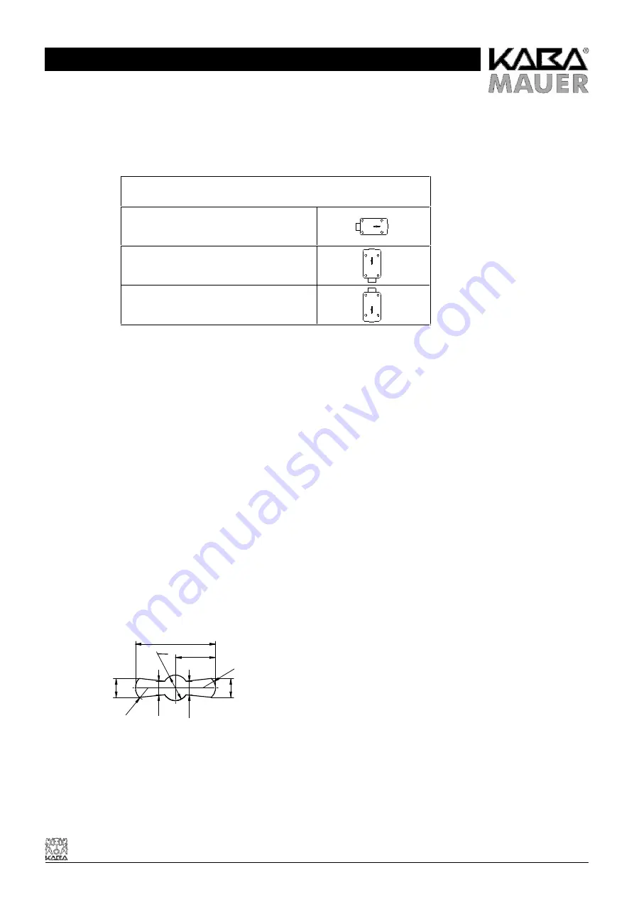
The lock can be mounted in the following positions:
-
RH version (standard version):
Lock mounting position
Bolt left, keyhole horizontal
Bolt downwards, keyhole vertical
Bolt upwards, keyhole vertical
•
Any variation of the lock or key may result in functional trouble and must better not be done. All claims under guarantee and
warranty will expire in this case.
•
Prevent the ingress of dirt into the lock.
•
Lock fastening: Use of M6 steel socket head cap screws or BSW ¼" steel bolts. The length of engagement must
correspond to the applicable standards considering the thickness of the lock of 25,7 mm and the screwing height of the lock
case of 19,7 mm.
•
Fastening screws: minimum property class 4.8 and maximum property class 8.8.
•
Screws to be secured either by lock washer, flat spring, tooth lock washer, fan type lock washer considering the diameter
(d1) or to be cemented.
•
Screw tightening moment: minimum 5 Nm and maximum 6 Nm.
•
The bolt must be floating in installed condition.
•
Perfect function of the lock and of any additional connected or triggered systems (e.g. boltworks) must be warranted and
checked by specialists during installation of the lock.
•
It must be ensured that the connecting cable is not damaged during installation. The protective cable casing (insulation) or
cable strands may not be damaged either, as otherwise there is a danger of short circuiting occurring. The cable should be
additionally protected against damage in the area of moving or sharp-edged parts by fitting protective casing or plastic
tubing. Care should be taken to ensure that the cable is not fitted with any kinks in it or in a compressed condition.
•
Use of the Kaba Mauer key guide (see Fig. 1) is recommended. Considering DIN 2768-mH, the keyhole in the door of the
secure storage unit should be dimensioned accordingly (see Fig. 1).
Fig. 1: Key guide 86101
R
4
R 4
O
8
4,2
4,2
5,9
5,9
25,5
12,75


