background image


COMBOBOXER 

Punch-Force measuring machine


Technical Information 


Summary of Contents for Comboboxer

Page 1: ...COMBOBOXER Punch Force measuring machine Technical Information...

Page 2: ...sage instructions 7 8 Maintenance check list problem prevention and day to day conservation 9 9 Quick check for potential errors 13 10 Machine setup 17 11 Spare parts and equipment 44 12 Standard repl...

Page 3: ...Usage Purpose Comboboxer is a punch force and kick force measuring machine The machine is designed to allow players to choose between two game types boxing and kicking This machine allows to measure p...

Page 4: ...200 4 Assembly Construction description Punch force and kick force measuring machine Comboboxer is built out of three main components base middle assembly top assembly The key component is a mother bo...

Page 5: ...ring mechanism consists of button START with backlight and electromagnets actual lowering mechanism kicking ball lowering mechanism consists of button START with backlight and electromagnets actual lo...

Page 6: ...ox should be placed in vertical position and the base should be leveled To level the machine correct tools should be used exp laser level or typical manual construction heavy duty level Turning severa...

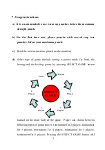
Page 7: ...e d Select type of game default setting is power mode for both the boxing and the kicking game by pressing SELECT GAME button located on the main body of the game Player can choose between following t...

Page 8: ...it in front of the machine for the punching bag to be released from the upper position for Boxer or for the kicking ball to be released from the blocked position for Soccer h For Boxer After the punch...

Page 9: ...he machine if needed use adjusting legs under the machine to bring the machine to level check if the usage instructions and disclaimers are readable Every month check mounting cover screws nuts check...

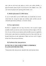
Page 10: ...too fast one should check if spring is properly stretched Spring can be adjusted with screw that is in the front left side after taking the masking net In case of forced lowering mechanism replacement...

Page 11: ...lb spec 12 Volt 3 Watt G Fuse replacement Machine is equipped with two long term fuses One at power supply assembly and the second one on the main electronic board specs 250V 4 A In case of short circ...

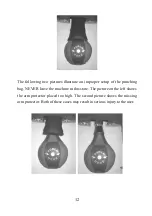
Page 12: ...proper setup of the punching bag NEVER leave the machine in this state The picture on the left shows the arm protector placed too high The second picture shows the missing arm protector Both of these...

Page 13: ...n Acceptor is not functioning 1 Check if it is not clogged up 2 Check for dust and dirt 3 Check strip connecting the main board with the acceptor Mechanism is not functioning 1 Using just power supply...

Page 14: ...HI LO shows this would indicate that sensor is working 2 Check if sensor cable is firmly connected to the main board 3 Check all wires to from the sensor Halogen lights are not functioning 1 Check po...

Page 15: ...anical counter did not come loose then turn the machine OFF and ON Bill Acceptor is not functioning 1 Check if power supply cable is hooked up to main board J3 2 Check if cable from bill acceptor is c...

Page 16: ...16 Red diode active on main board 1 Usually caused by circuit being shorted at scale bulb array check all cables for potential shortage...

Page 17: ...17 10 Machine setup Main Board Layout Back Side Drawing 1...

Page 18: ...10 connector for buttons GAME and START BOXER J11 connector for mechanical counter J12 connector for speaker SW ADD connector for START KICKER S1 service setting switches S2 step potentiometer for set...

Page 19: ...SW2 ARE LOCATED IN THE LOWER LEFT PART OF THE MAIN CIRCUIT BOARD Switch 1 THIS SWITCH IS USED TO ENTER THE PROGRAM SETTINGS PLEASE USE BUTTONS SW1 OR SW2 FOR FINDING THE RIGHT PROGRAM P01 P96 DESCRIPT...

Page 20: ...et to 2 1 NOTE IF THE BILL ACCEPTOR IS SET 4 PULSES FOR A 1 SET P09 TO 12 in case of the older software to 5 P05 YOU CAN SET ADDITIONAL CREDITS BONUS CREDITS WHEN A SET DOLLAR AMOUNT IS INSERTED USING...

Page 21: ...SIRED UNATTAINABLE POWER HIGHEST SCORE YOU MUST TURN SWITCH 5 TO ON POSITION IMPORTANT AFTER YOU SET THE RECORD AND PUT SWITCH 5 TO ON POSITION YOU MUST TURN OFF THE MACHINE FOR 5 SECONDS P09 THIS FUN...

Page 22: ...CKETS RANGE FROM 0 990 FACTORY SETTING IS 0 P15 SETS HOW MANY TICKETS WILL BE GIVEN OUT AFTER REACHING THE BREAKING POINT AS THE FIRST VALUE RANGE FROM 0 20 FACTORY SETTING 0 P16 POINT INCREMENT IN AN...

Page 23: ...80 7 280 0 320 8 320 0 360 9 360 0 400 10 400 0 440 11 440 0 480 12 480 0 520 13 520 0 560 14 560 0 600 15 600 10 640 16 640 12 680 17 680 14 720 18 720 16 760 19 760 18 800 20 800 20 840 21 840 22 88...

Page 24: ...00 Note Setting prize 3 is available in this mode but does not have any meaning and is reserved for future expansions 1 NOT USED 2 NOT USED 3 IN THIS MODE WINNING IS BASED ON A RANGE OF NUMBERS P59 TO...

Page 25: ...THIS COUNTER REPRESENTS THE NUMBER OF POINTS QUARTERS COLLECTED FOR POSSIBILITY OF WINNING PRIZE 1 CAN BE RESET BY PRESSING HOLDING START BOXING BUTTON P28 COUNTER FOR NUMBER OF COLLECTED POINTS QUAR...

Page 26: ...MBER CAN BE SET IN THE RANGE OF 0 50 DEFAULT SETTING 10 WORKS FOR P23 0 P36 NOT USED P37 COUNTER SHOWING THE NUMBER OF PRIZE 1 WINNERS CAN BE RESET BY PRESSING HOLDING START BUTTON WORKS FOR P23 0 P38...

Page 27: ...OWEVER IT INCREASES THE CHANCES OF WINNING RANGE 10 10000 SKIP COUNT 10 DEFAULT VALUE 400 P43 SETTING OF THE FIRST MAGIC NUMBER ITSELF RANGE 100 999 DEFAULT VALUE 777 THE FUNCTION IS OFF WHEN P43 0 P4...

Page 28: ...BER PRIZE 6 THIS REPRESENTS THE NUMBER OF POINTS QUARTERS ACCUMULATED BEFORE THE POSSIBILITY OF WINNING THE SECOND MAGIC NUMBER PRIZE SET IN P55 RANGE 10 10000 SKIP COUNT 10 DEFAULT VALUE 400 REACHING...

Page 29: ...OR RANGE PRIZE 3 RANGE 700 997 DEFAULT SETTING 750 SEE P59 P64 LOWER SCORE LIMIT FOR RANGE PRIZE 3 RANGE 100 997 DEFAULT SETTING 700 SEE P59 P65 ADDITIONAL CREDIT COUNT METHOD IF SET TO 1 IT WILL GIVE...

Page 30: ...NNECTION ALTHOUGH NO DATA IS SENT WHEN P67 0 AFTER SETTING TIME IN P67 MACHINE HAS TO BE TURNED OFF AND TURNED BACK ON P68 SETTING FOR FLASHING LIGHTS IN IDLE STATE P68 0 OFF P68 1 TO 60 MINUTES BEFOR...

Page 31: ...UCH AS 111 222 999 2 THE SURPRISE BALL CAPSULE DISPENSER IS ON FOR MULTIPLES OF 100 ONLY 3 THE SURPRISE BALL CAPSULE DISPENSER IS ON FOR TRIPLE NUMBERS ONLY DEFAULT SETTING IS 0 OFF P78 ACTIVATION OF...

Page 32: ...0 00 10 MINUTES TO 1 HOUR 1 MINUTE JUMP DEFAULT SETTING IS P82 00 00 30 30 SECONDS Example when P82 is set to 10 every 10 seconds halogen will not shine pause IMPORTANT P82 CAN BE SET BUT IT ALWAYS HA...

Page 33: ...ER AUTOMATIC OR MANUAL USING THE DIP SWITCH 4 WORKS WITH P87 P87 DEFINES FOR HOW LONG TIME IN MINUTES MACHINE NEEDS TO BE IN THE IDLE STATE NOT OPERATED BUT TURN ON FOR THE SCORES TO BE RESET THE LIMI...

Page 34: ...AKING POINT DEFAULT SETTING 850 P92 NEEDS TO BE SET P94 SETTING SIREN AFTER MONEY INSERT SETS THE SIREN SIGNAL DURATION TIME 0 THE FUNCTION IS OFF 0 1 10 SECONDS FOR WHICH SIREN WILL BE ON 0 1 SECOND...

Page 35: ...OU WILL ACTIVATE UNATTAINABLE RECORD HIGHEST SCORE WHICH YOU MUST SET BEFORE IN P08 SERVICE KEY REMEMBER TO ACTIVATE THIS RECORD YOU MUST TURN OFF AND TURN ON THE MACHINE Switch 6 7 TURNING ON OFF BOX...

Page 36: ...tivity switch S2 THE SENSITIVITY CAN BE CHANGED BY ROTATING SWITCH S2 AFTER THE SWITCH IS ROTATED THE SENSITIVITY LEVEL WILL BE SHOWN ON THE CREDIT DISPLAY LOWER LEVEL NUMBERS CORRESPOND TO GREATER DI...

Page 37: ...37 Main Board Layout Front Drawing 2 Drawing 3...

Page 38: ...38 Boxer Power Supply Layout Drawing 4 Kicker Power Supply Layout Drawing 5...

Page 39: ...39 Main Power Supply Layout Front view Drawing 6 Mechanical counter 2 wire from mechanical counter 1 wire from mechanical counter Drawing 7...

Page 40: ...40 Sensor 1 Emitter 2 Cathode 3 Anode 4 Collector Drawing 8...

Page 41: ...peaker 3 unused 4 unused Drawing 9 Buttons Start Boxing Game 1 2 START game Boxer 3 4 GAME selection 5 6 bulbs lighting button Start 7 8 bulbs lighting button Game SW ADD 1 2 START game Kicker 5 6 bul...

Page 42: ...icket dispenser 2 red 12V 6 green signal 3 black 12V 2 6 3 2 6 3 1 4 5 Drawing 10 Hopper Motor Hopper 2 1 5 6 2 6 3 1 4 5 Drawing 11 Thermal printer Main board Thermal printer Hopper 2 2 6 3 1 4 5 Dra...

Page 43: ...300 6 300 7 500 8 500 9 700 10 700 11 900 12 900 13 Select Game 14 Select Game 15 Force 16 Force J 7 1 100 2 100 3 300 4 300 5 500 6 500 7 700 8 700 9 900 10 900 11 Select Game 12 Select Game 13 not u...

Page 44: ...r 1 piece 12 Standard replacement parts Front panel bulbs 73 bulb SELECT GAME button bulb 161 Main power supply Switching power supply 12V 12A 5V 5A Halogen bulb 12v 20W MR11 C GU4 35mm DIA 13 Require...

Page 45: ...counter P01 can be reset by pressing and holding switch SW1 for 3 seconds after resetting machine will switch to regular work mode HOW TO ACCESS QUICKLY RESETABLE P01 MONEY COUNTER without opening the...

Page 46: ...ll be extend for another 15 seconds If the testing mode is not used for 15 seconds machine will switch to regular working mode HOW TO SET UP PRICE OF THE GAME PLAY Enter the settings mode by powering...

Page 47: ...one game credit is to cost 1 the setting would then be 4 1 meaning that 4 quarters equals one punch There is one number you must set here and this is done by the machine s START BOXING button in the...

Page 48: ...switching DIP switch 1 to ON position The main display should now indicate the settings mode with P 1 as shown Press the SW1 button repeatedly on the main board until the main display reads P 5 If yo...

Page 49: ...shown START BOXING sets the left value and GAME sets the right value Repeat the procedure for P 6 but remember to set the bonus for a larger amount of money than in P 5 Example could be for 10 20 cre...

Page 50: ...ombination The magic number as well as the frequency of hitting that number must be set Enter the settings mode by powering up the machine and switching DIP switch 1 to ON position The main display sh...

Page 51: ...et to setting P42 which is the minimum amount of credits collected by the machine to unlock the possibility of hitting that number Here again use the same buttons to adjust the value Remember that thi...

Page 52: ...r the reset mode by powering up the machine and switching DIP switch 4 to ON position You will not see any changes on the display and the game will remain in playable mode This is why it is important...

Page 53: ...es not get too high follow the instructions below The highest score will be reset to the value programmed in setting P30 see setting P30 Enter the settings mode by powering up the machine and switchin...

Page 54: ...ighest score should be reset automatically eg set 120 Then press the SW1 button once the main display should read P87 Using START BOXING button on the front of the machine set number of minutes counte...

Page 55: ...be reset HOW TO ERASE CREDITS Erasing the game s credits can be done with the following procedure Enter the settings mode by powering up the machine and switching DIP switch 1 to ON position The main...

Page 56: ...button located in the front of the game When finished don t forget to set DIP switch 1 back to OFF position HOW TO CHANGE THE PUNCHING BAG Changing the punching bag is required in some cases Lower the...

Page 57: ...the second bolt will prevent the bag from properly tightening of the assembly Insert the bag in its place replace the tension nut and tighten it until the bag cannot be twisted by manual tests To tes...

Page 58: ...er the bag and find the mechanical hammer holding the entire arm in position Then using your thumb press the hammer which is under compression by a spring behind it and the bag should be free to come...

Page 59: ...ard Each power supply is labeled if you want to check punching bag press the button on power supply labeled Boxer if you want to check kicker soccer arm press the button on power supply labeled Kicker...

Page 60: ...ng the solenoid is necessary The solenoid can be evaluated in another way if for example you do not have a multi meter handy This also involves unscrewing the two terminals and pulling out the two wir...

Page 61: ...6 P7 P37 P67 P8 P38 P68 P9 P39 P69 P10 P40 P70 P11 P41 P71 P12 P42 P72 P13 P43 P73 P14 P44 P74 P15 P45 P75 P16 P46 P76 P17 P47 P77 P18 P48 P78 P19 P49 P79 P20 P50 P80 P21 P51 P81 P22 P52 P82 P23 P53 P...

Page 62: ...62 MAIN BOARD SETTINGS P91 P92 P93 P94 P95 P96...

Page 63: ...protector condition Arm protector position Legibility of disclaimer Legibility of instruction Level of machine Grease on mechanism Bulbs Buttons Bill and coin validators Safe condition Yes No SERIAL N...

Page 64: ...protector condition Arm protector position Legibility of disclaimer Legibility of instruction Level of machine Grease on mechanism Bulbs Buttons Bill and coin validators Safe condition Yes No SERIAL N...

Reviews: