background image


SK-50 

ARF 

ASSEMBLY MANUAL 


Kangke Industrial USA, Inc.  65 East Jefryn Blvd.  Deer Park NY 11729 

http://www.kangkeusa.com

      E-mail:  

info@kangkeusa.com


Tel: 1-877-203-2377   Fax: 1-631-274-3296 

Summary of Contents for SK-50

Page 1: ...SK 50 ARF ASSEMBLY MANUAL Kangke Industrial USA Inc 65 East Jefryn Blvd Deer Park NY 11729 http www kangkeusa com E mail info kangkeusa com Tel 1 877 203 2377 Fax 1 631 274 3296 ...

Page 2: ... tip pen Screwdrivers Pliers Sewing thread 5 32 drill 1 8 drill 1 16 drill Read each step of the instructions carefully Be sure you understand what is required and what the procedure is before you glue or cut anything How well you assemble this model will have a direct effect on its flight characteristics This manual is the sole property of Kangke Industrial USA Inc Reproducing any part without th...

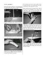
Page 3: ...t up Read the procedure and gather the materials before starting Mix a small amount of 30 minute epoxy Spread the epoxy in the dihedral box top bottom and sides about 1 inch in on both wing panels The snug fit of the brace will push it down the box Apply epoxy to one half of the wing spar and slide it into position Spread the epoxy that oozes out over the wing mating surface as well as the other h...

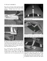
Page 4: ...red and square to the fuselage DO NOT GLUE Use a felt tip pen to mark the outline of the fuselage on both the top and bottom of the stabilizer Remove the stabilizer Cut through the covering about 1 8 inch inside the lines and carefully remove the covering exposing the wood Be careful not to cut into the wood as this would weaken the structure Slide the stabilizer back into the fuselage leaving 3 8...

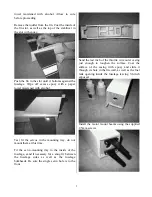
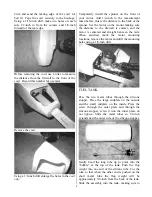
Page 5: ...ray do not mount them at this time Fit the servo mounting tray to the inside of the fuselage sand if necessary for a snug fit between the fuselage sides as well as the fuselage bulkheads Be sure the single servo hole is to the front Sand the last inch of the throttle wire outer casing just enough to roughen the surface Coat the surface of the casing with epoxy and slide it through its hole in the ...

Page 6: ...ect and the motor is centered and straight between the rails When satisfied mark the motor mounting locations remove the motor and drill the mounting holes using a 1 8 inch drill FUEL TANK Pass the two metal tubes through the silicone stopper Place the large endplate on the outside and the small endplate on the inside Press the screw through the outer plate and through the silicone stopper screw i...

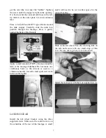
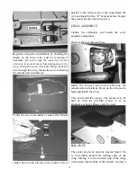
Page 7: ...off RTV silicone around the tank at the fuselage bulkhead Do not make one continuous bead as the silicone is used as a vibration absorber Several small spots will work better and be lighter LANDING GEAR Install the tail wheel bracket using the three supplied screws Make sure the control arm is on the centerline of the rear of the fuselage A small notch will need to be cut to allow space for the su...

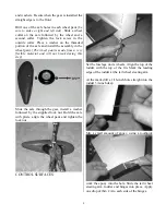
Page 8: ...rial and will not break during this step Slide the axle through the gear install a washer followed by the supplied lock nut Hold the axle with pliers align the wheel pant and tighten the lock nut CONTROL SURFACES Set the fuselage on its wheels Align the top of the rudder with the top of the fin Mark the leading edge of the rudder at the tail wheel steering arm At the mark drill a 1 16 inch hole st...

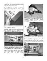
Page 9: ...retor and vent tubes Install the motor using the four supplied screws washers and lock nuts Make a Z bend at one end of the throttle control wire Install the Z bend in the carburetor Slide the other end of the throttle control wire through the outer casing and place the carburetor on the motor Do not tighten Bend the wire slightly till throttle operation is smooth and does not bind Temporarily hoo...

Page 10: ...s on the elevator control rod now need to be spread apart Make two equal bends one in each wire 3 8 inch from the end of the wood rod Bend the wire until the threaded ends are 2 inches apart To insert the control rod into the fuselage tie a string around the fork and pull the ends together as shown Slide the control rod into the fuselage line the wires up with the fuselage slots and pull the strin...

Page 11: ...rk the wire and install with a Z bend as before Repeat the process for the other wing servo FINAL ASSEMBLY Tighten the carburetor and install the cowl propeller and spinner Hook up the fuel and vent lines Install the receiver and switch following the manufacture instructions Hook up the wing servo leads and install the wing Trim and install the canopy The canopy may be held on with the provided sc...

Page 12: ...irectional control Once the tail is up apply a little up elevator and allow the plane to gently lift off the runway Keep the climb angle and turns shallow until you reach a safe altitude Reduce the throttle to about 60 power With the airplane flying away from you adjust the radio aileron trim tab till the wing stays level Turn and line up the plane with the runway Adjust the elevator trim till the...

Reviews: