background image


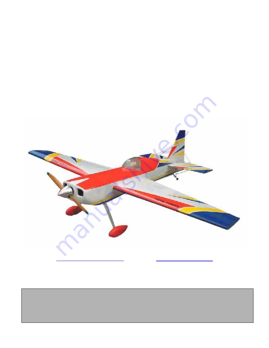
TEXAS HURRICANE 

ARF 

ASSEMBLY MANUAL 


Kangke Industrial USA, Inc.  65 East Jefryn Blvd.  Deer Park NY 11729 

http://www.kangkeusa.com

      E-mail:  

info@kangkeusa.com


Tel: 1-877-203-2377   Fax: 1-631-274-3296 


This manual is the sole property of Kangke Industrial USA, Inc. Reproducing any part without the 
consent of Kangke Industrial USA, Inc. is a lawful violation. 

Warranty: 

Kangke Industrial USA Inc. guarantees the kit to be free of defects in both material and workmanship at the date of 

purchase. This warranty does not cover any parts damaged by use or modifications. In no case shall Kangke Industrial’s liability 
exceed the purchase cost of this kit. Since Kangke Industrial has no control of final assembly and material used by user for final 
assembly, no liability shall be assumed or accepted for any damage resulting from the use by user of final user-assembled products. 
This kit has been flight test for normal use. If the plane will be used for extremely high stress flying, the modeler is responsible for 
reinforcing the high stress points. Inspect this kit immediately after receiving it, report any missing and damaged parts within 7 
business days otherwise the claim may be denied. 


1

Summary of Contents for TEXAS HURRICANE

Page 1: ...rranty does not cover any parts damaged by use or modifications In no case shall Kangke Industrial s liability exceed the purchase cost of this kit Since Kangke Industrial has no control of final assembly and material used by user for final assembly no liability shall be assumed or accepted for any damage resulting from the use by user of final user assembled products This kit has been flight test...

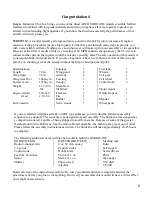
Page 2: ...ow 140 210 Gas 2 10 3 4 Kit Contents Fuselage 1 Wing panel 2 Ailerons 2 Cowling 1 Canopy 1 Main Gear 1 Stabilizer 1 Elevator 2 Fin 1 Rudder 1 Servo mount 1 Fuel tank 1 Wheels 2 Tail gear 1 Tail wheel 1 Control horn 6 Motor mount 1 Hardware pack 1 Manual 1 Wheel pants 1 If you are familiar with the assembly of ARF type airplanes you will find the following assembly sequence to be unusual The sequen...

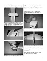
Page 3: ...down from the fin top This will place them in the center of the horizontal support in the fin Measure and locate the exact center of the stabilizer Using a felt tip pen draw a line on center Carefully line up the rudderpost Slide the stabilizer in position with the centerline in the middle of the rudder slot Insert a pin in the center of the turtle deck at the top of the fuselage Move the string f...

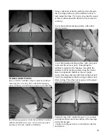
Page 4: ...ture Peel away the covering Cover the stabilizer mating surface with a thin layer of epoxy Cover the fuselage mating surface with wax paper to prevent the excess epoxy from gluing the stabilizer support to the fuselage Assemble the stabilizer and its mating surface using the drawn lines for alignment Install on the wax paper covered fuselage and carefully line up the tail post Verify the alignment...

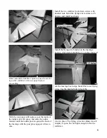
Page 5: ...ge with the post pins engaged Allow to cure Install the two stabilizer lock down screws with knurled nuts Bend the flying wire mounts to 45 degrees and install as shown Install the flying wire bracket on the fuselage bottom The bracket should be 5 inches forward fr om the fuselage back edge Install the lower flying wires Use the knurled nuts to lock the cle vises in place The flying wires are adju...

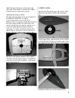
Page 6: ...rizontal centerline by measuring 2 inches up from the bottom of the engine support Locate the vertical centerline 1 4 inches to the LEFT of the engine support center The back of the spinner should be no less than 5 5 8 inches from the engine support The BRISON 2 4 used in the prototype required a inch spacer made from hard wood LANDING GEAR Slide the axle through the deep offset in the wheel Insta...

Page 7: ...ce aerobatics or 3 D flight The following are the torque requirements for this level of performance as well as the servos used in the prototype Ailerons 50 oz in prototype used HITEC HS 625MG Elevators 60 oz in prototype used HITEC HS 625MG Rudder 100 oz in prototype used HITEC HS645MG Throttle Standard servo HITEC HS425BB CAUTIONS Gas engines because of the ignition systems require some special c...

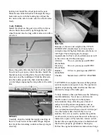
Page 8: ...forward of the flying wire bracket Fabricate hardwood mounts and epoxy them in the fuselage The servo may be recessed into the fuselage to match your servo Install the servo following the manufacture instructions With this configuration either pull pull or push rod control may be used Pull pull is more precise and the preferred method STANDARD PULL PULL RUDER SERV0 Drill a 3 16 inch hole in the fu...

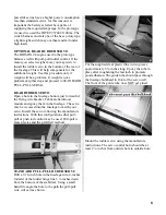
Page 9: ... some like to loop the cable through the control horn while others like to use a clevis Use the system you are most comfortable with Remove the covering from the exit slots in the servo bay doors Mount the elevator servos on the servo bay doors Pre drill the screw holes to prevent the rails from splitting If your radio does not support two elevator servos it will be necessary to use a Y harness It...

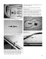
Page 10: ...ntrol horn back plate line up the edge with the top of the elevator bevel 5 8 inch out from the inside corner of the elevator Drill a hole at this location Install the elevator control horn using a screw backing plate and a control link The elevators get the mid size horns Be sure the servo is centered and the elevator neutral Measure and fabricate a control rod For sport flying 2 56 rods will wor...

Page 11: ...protrude to the outside The second short tube fill drain should be 1 8 inch beyond the inner plate Bend the long tube as shown to the tank top Insert the flop weight in the end of the supplied flop tube Cut the flop tube just short enough so the flop weight cannot touch the tank end when assembled Lube the rubber stopper lightly with cooking oil align the vent tube with the tank top and carefully ...

Page 12: ...py for best fit tape securely Drill two 1 8 inch holes in each side of the canopy only then secure with the supplied screws Remove the screws and harden the threads with CA An alternative method if you don t want the canopy removable it may be glued on using canopy adhesive Additional trim may be added as desired If you engine requires ignition and battery now is the time to install them Install t...

Page 13: ...ill provide the most stability As your comfort and skill increase slowly move the C G aft to increase the control response The recommended starting range for the C G is 4 3 4 inches to 5 1 4 inches back from the leading edge of the wing measured against the side of the fuselage Turn the aircraft upside down and support it at that location Because of the mid wing configuration it is very difficult ...

Page 14: ...ect the aileron trim after this procedure Continue to fly and trim until the aircraft is tracking well land before the fuel runs out Carry a little power on final approach until over the end of the runway then cut power to idle hold the plane just off the runway till the airspeed bleeds off and the plane settles on If the landing is too long add power go around and try again don t try to force it ...

Page 15: ...e shim the back of the main wing 1 8 inch at a time till the elevator is neutral If up elevator is required shave the rear of the wing saddle 1 8 inch at a time Engine Thrust Angle Up Down On a low pass 50 power crosswind go to 80 power and pull vertical at the same time As the model slows do not correct path with elevator If the model tries to loop add 1 16 inch shims to the top motor mount bolts...

Reviews: